2. Digital bodies
Life is information. The digital encoding contained in our DNA defines not just the color of our eyes, but also the shape of our bodies. Latter, in our lives, our body also reflects what we have done with it. Genetics (plans) and nutrition (material) are the only elements needed to build something as complex as a living human. Our bodies are our houses and maybe the only thing that really belong to us.
The body also have information related to the universe. Each atom exists in a time and space that work in the realm of a ubiquitous bended fabric of time-space. And also its position, it's coordinates, and their own existence depends on quantum mechanics. The micro and the macro working in coordination.
We are living in exciting times, as we are able now to capture and process that information (at our own scale), and process it to develop art, science and technology.
3D Scanning
We experimented with the technology of getting our meshes from 3D scanning. In this case it is convenient, because we are aming to capture a model at scale 1:1.
We used the software and hardware from Snatect, that uses infrared technolgy for point capture and also photography for UV information.
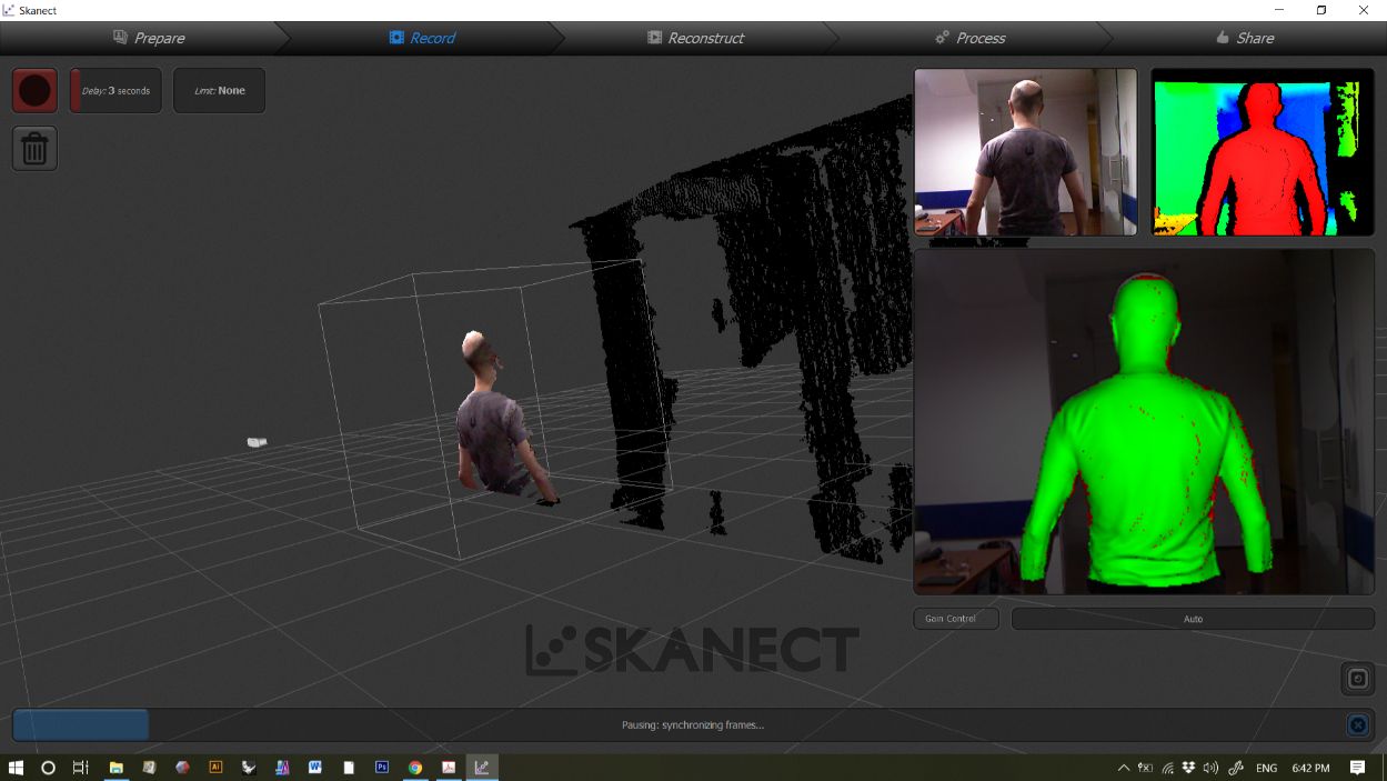
The results came out pretty well. Here are some settings for the scanning:
We used a 0.8 m3 volume as a scanning domain. We used this size with a torso mannequin construction in mind.
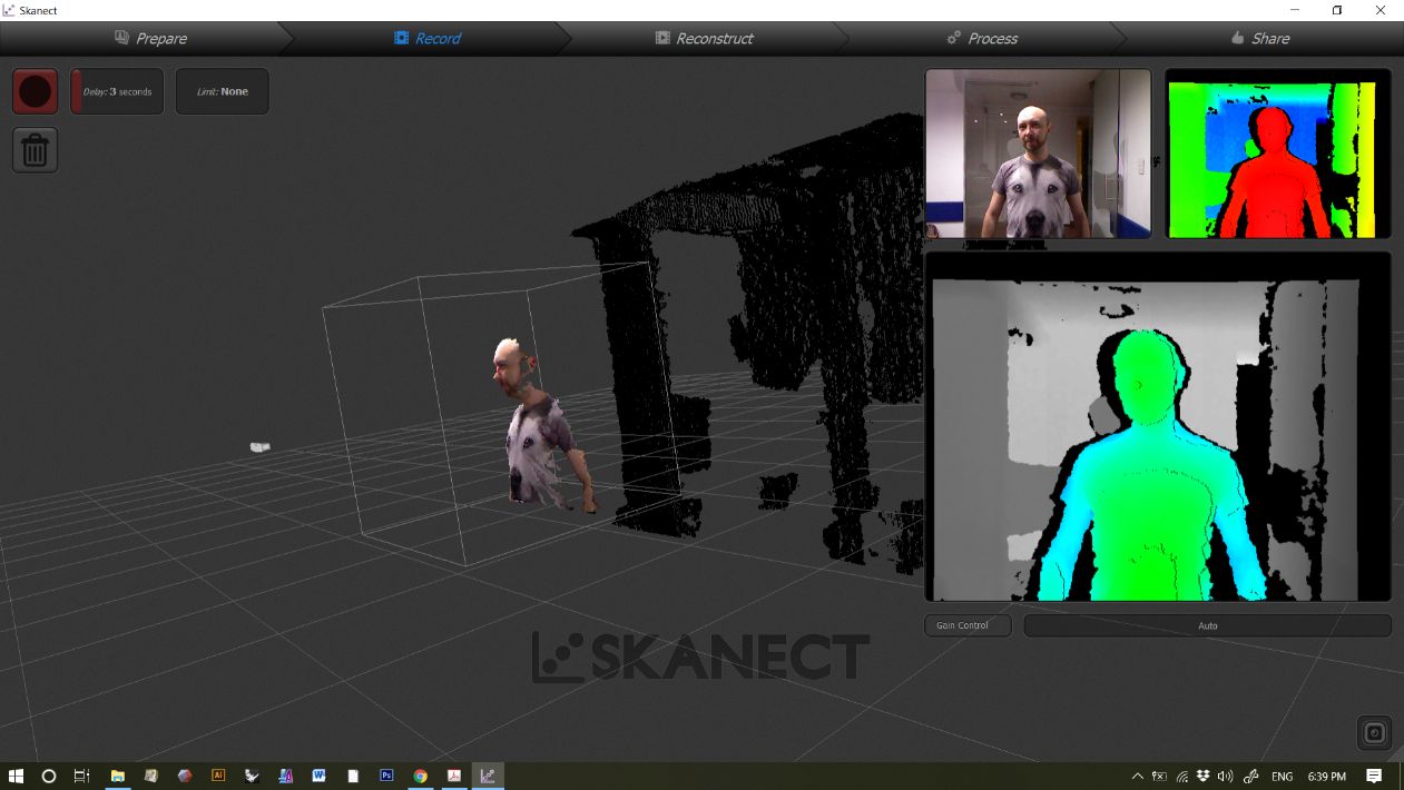
We can see a color code for the regions already scanned and the valid and invalid distances. The spots shown in green are the gathered data.
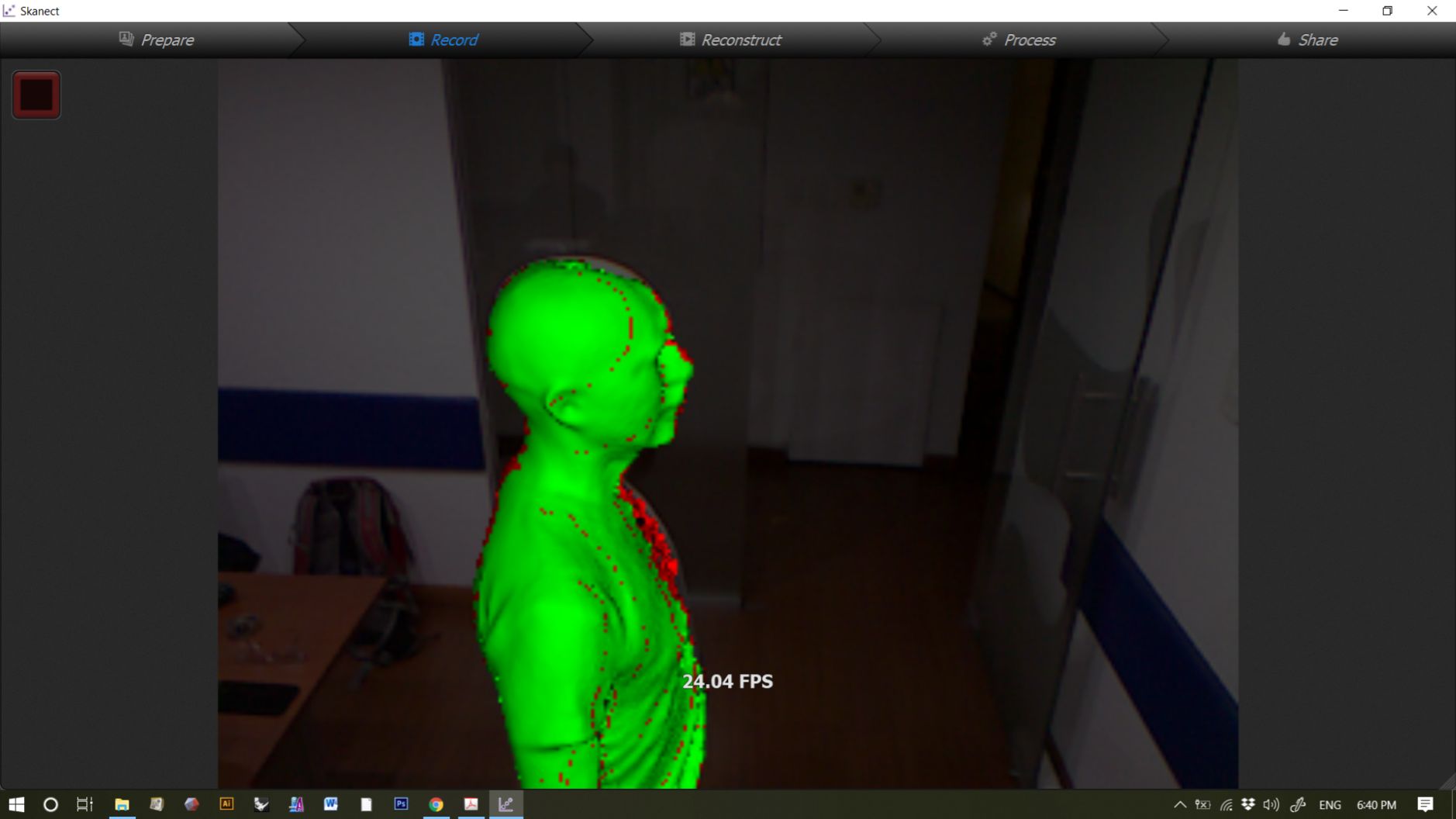
We can see also a frame rate of capture. In this case 24.04 frames per second.
Once the scanning is done, we still have to wait for the data processing. Once we have it, we can use the software for processing.
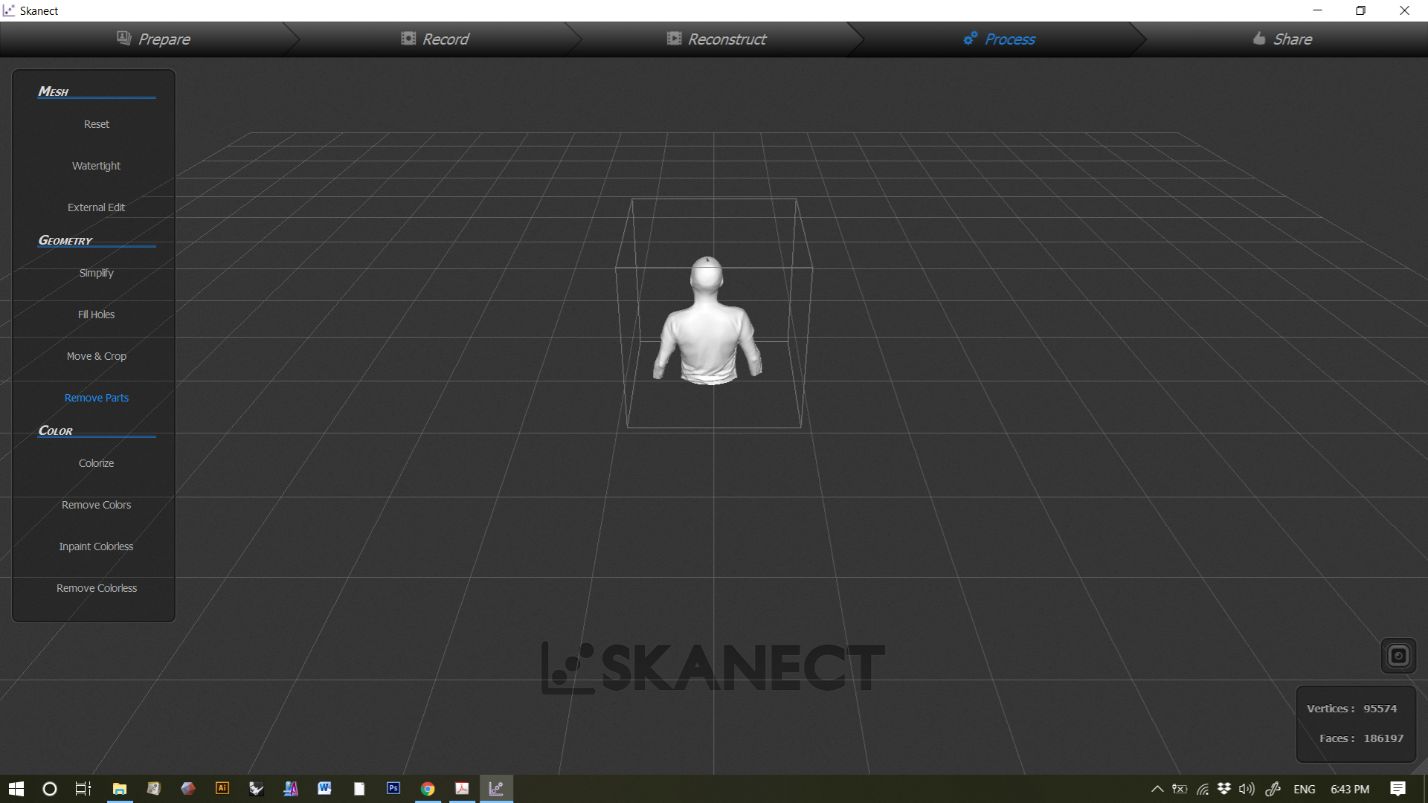
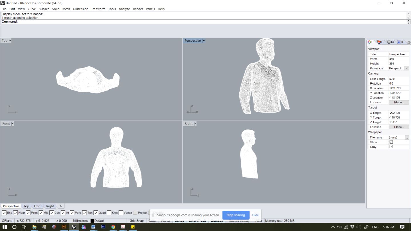
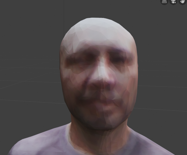
The principal mesh operation that we apply is the watertight operation. This algotithm closes the mesh, as it were hermetic. It is usefull, but it has it's dawbacks, that we need to fix latter. We can also see above the mesh without texture information, as an STL file, and bellow, the image with texture information (UV), as in a OBJ file.
We can see the errors in the algotithm, as on the top of the head an artifact is created. We'll deal with it latter.
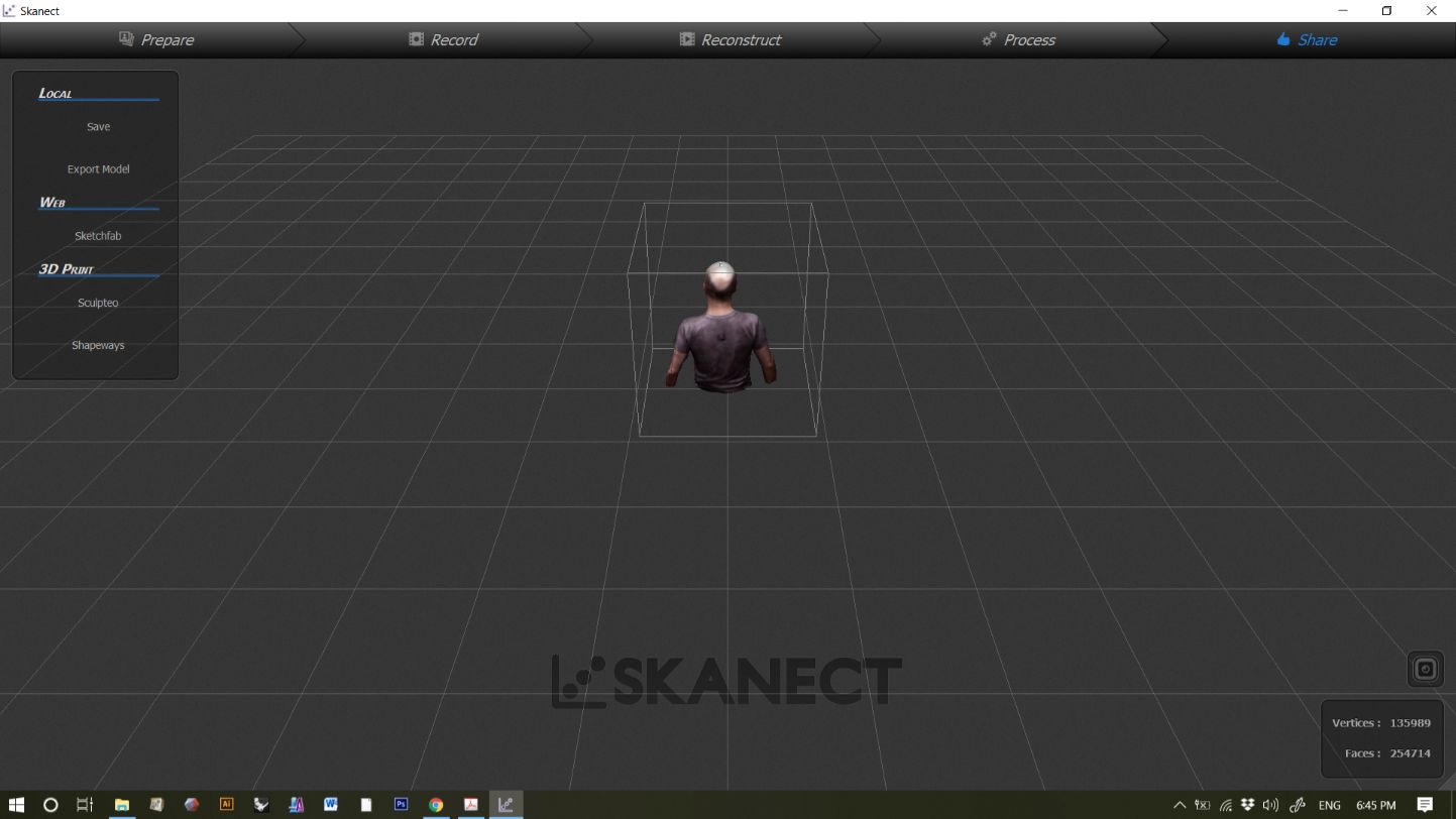
Here we can see it in other view.
Mesh processing
A mesh is an object described mathematically and geometrically as a set of points that also defienes vertices and faces.
After 3D scanning, usually it is necessary to edit the mesh obtained to get the results you want. In this case I used the program Blender 2.8, the current version at this time. Blender is open source, multiplataform and can also integrate Python code.
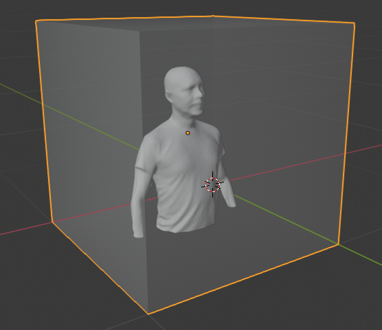
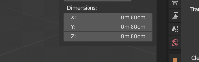
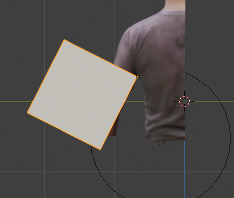
First, I imported the image from the scanner. I set the scale to 0.8, because the scanning was set at 0.8m3 instead of 1 m3. This was a mistake, that was carried out to the end of the process. Here, the cube had to be 1m3, not 0.8m3. Latter it was corrected.
Here we see the cube meassurements (wrong). This caused the tags problems, and was corrected later.
Here we can see the scanned mesh imported and selected in Blender.
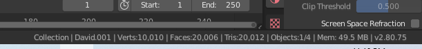
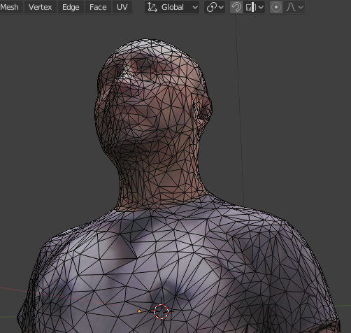
At the bottom, we can see the properties of the mesh. We see we have aprox. 10.000 vertices and 20.000 faces and related tris. This is way high for our requirements, and we fix it in another copy. Maybe for other purpouses we´ll need the high resolution version.
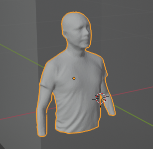
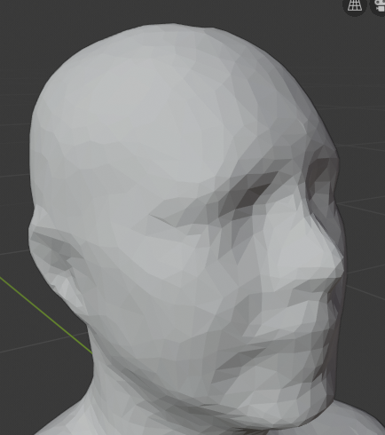
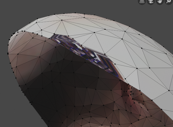
This is a close up of the high poli (many poligons) mesh. Now we apply a modifier (processes already programmed in Blender).
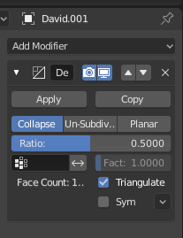
First, select the mesh and then, in the mesh modifier choose the collapse option with a ratio of 0.5 (50%). It is posible to go lower depending on the mesh.
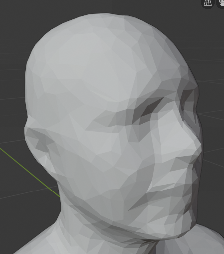
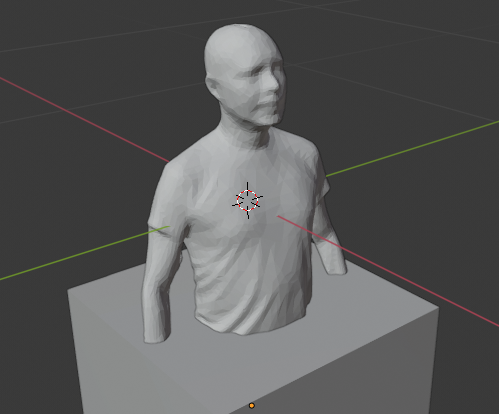
We can see the result in the view port. We don´t loose so much detail.
We can see the second mesh with a UV info. Just to have an idea of how it looks like.
And here with the mesh. we can see that, from the scanning, certan detailed parts are more dense than others.
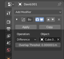
Then, I added a cube, scale it and intersect it to the bottom part of the mesh. I am planing to boolean-cut it. First, we select the mesh, then we apply a boolean modifier with the parameters: Difference as operation, and cube as an object. In Blender, the modifiers are non-destrucrive, what is usefull for some applications, but for machinig and fabrication it is better to actually change the mesh. That is why at this point we apply those modifiers (no way back, so work on a copy to save version).
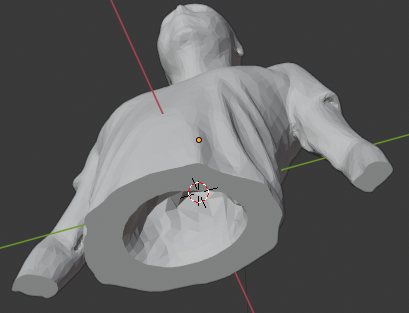
After the operation, we have to delete the cube and we see the results. It cut the arms, but not the trunk of the body. I think Blender is still a little buggy, but the community is going to fix this one day.
In any case, I reapplied the modifier with another cube.
And got the results I wanted (almost). I can see here that I have an artifact in the middle of the trunk.
To fix it we get into edit mode (selecting the object and hitting the tab).
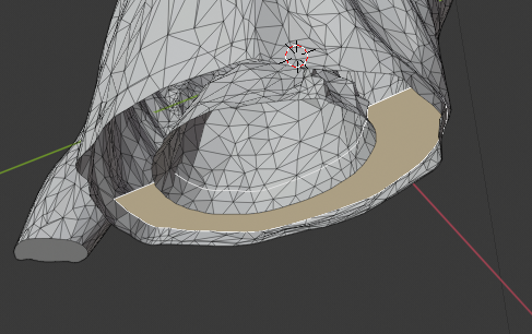
Then we select the four bigger areas and delete them.
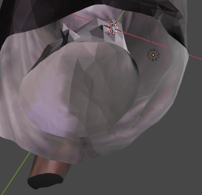
After deleting them, we still have a complex artifact area "floating". To delete it we must have to select all the faces that composes it. To do that, first we select one of them.
And hold ctrl+ "+ sign" to select chain. You can do this with vertices and side selection. Do that a few times and you have the complete area selected.
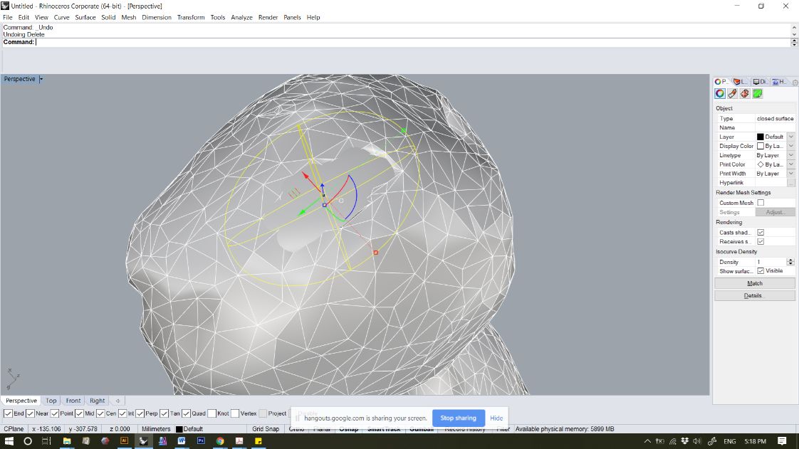
Then just clic "delete". Through the hollow body we can still see the artifact inside the head. I will fix it latter.
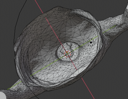
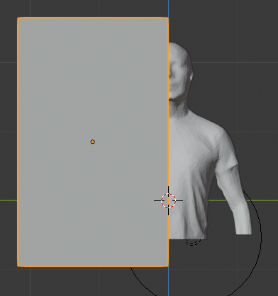
First, I will cut the mesh in the middle. Latter I had to redo the mesh, and I din´t do this step, but this time I wanted a symetrical mesh. In any case, I cut it with a... guess... cube.
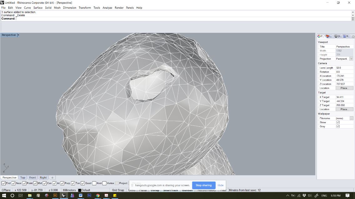
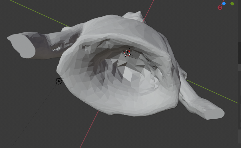
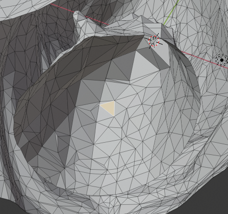
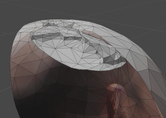
Once cut, the head artifact is very evident.
A close up of the artifact.
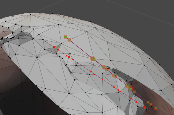
It is possible to use the knife toll to cut the bridge that attaches the artifact with the main body.
Once separeted, we select the pieces that we don´t want, and delete them.
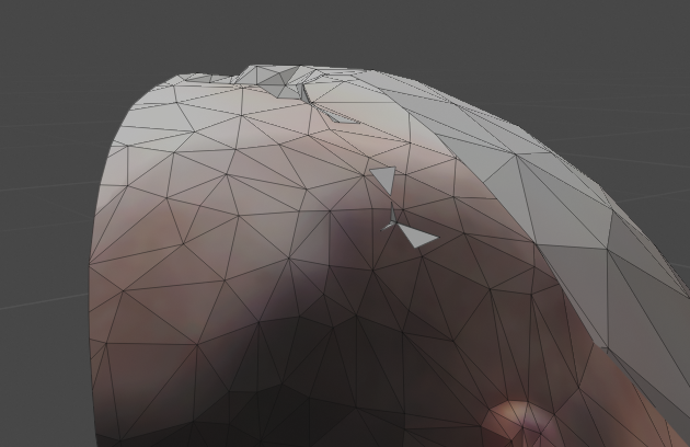
Once deleted, we create a border selecting two points, and applying the create faces/sides in the vertices menu.
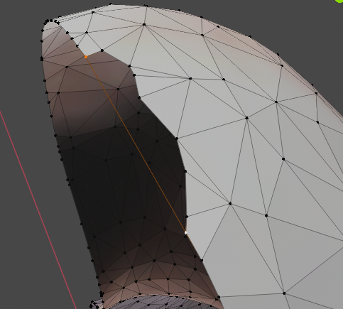
Then we select the points surrounding the area missing, and applying the previous tool.
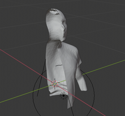
Here we see the cube-cutting method used in an arm. We recreate the rest of the mesh with a Mirror modifier.
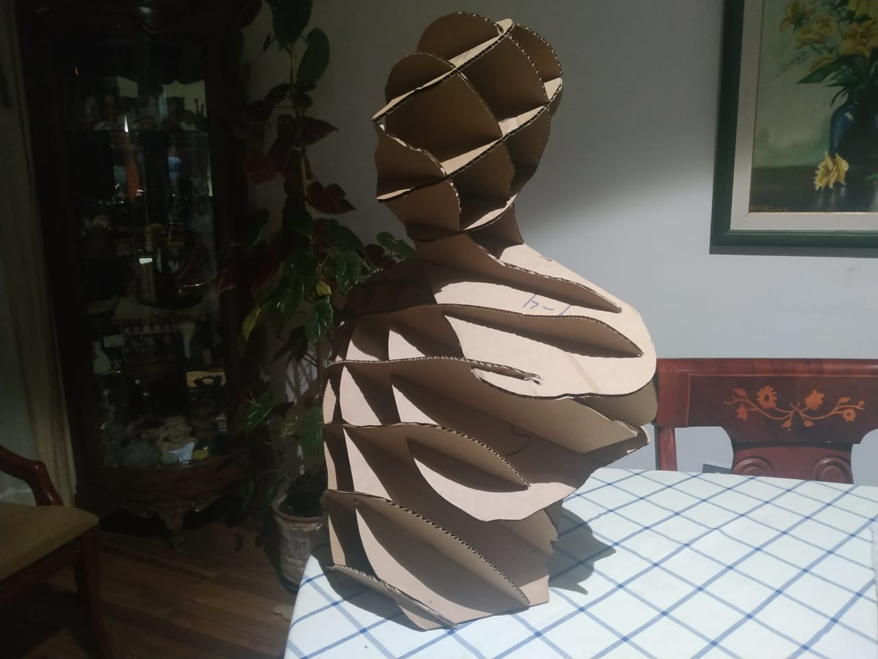
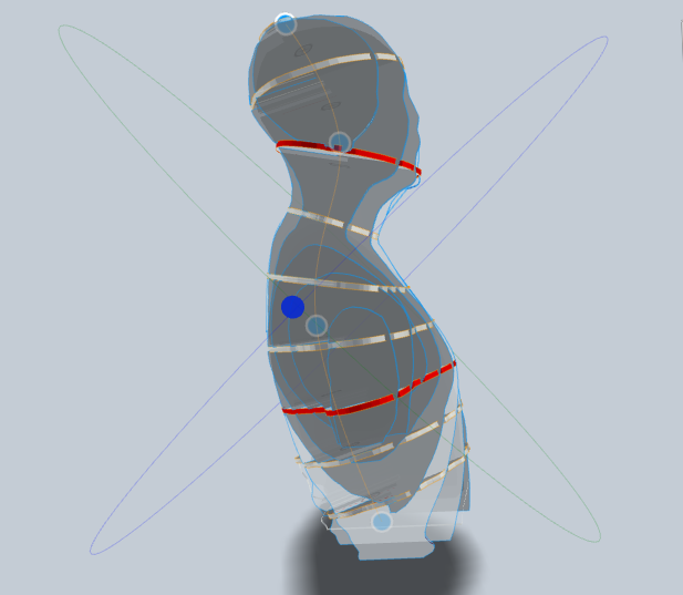
This part is for the Slicer. I used the curved slices tool following the shape of the spine. I think it gives the body a natural flow.
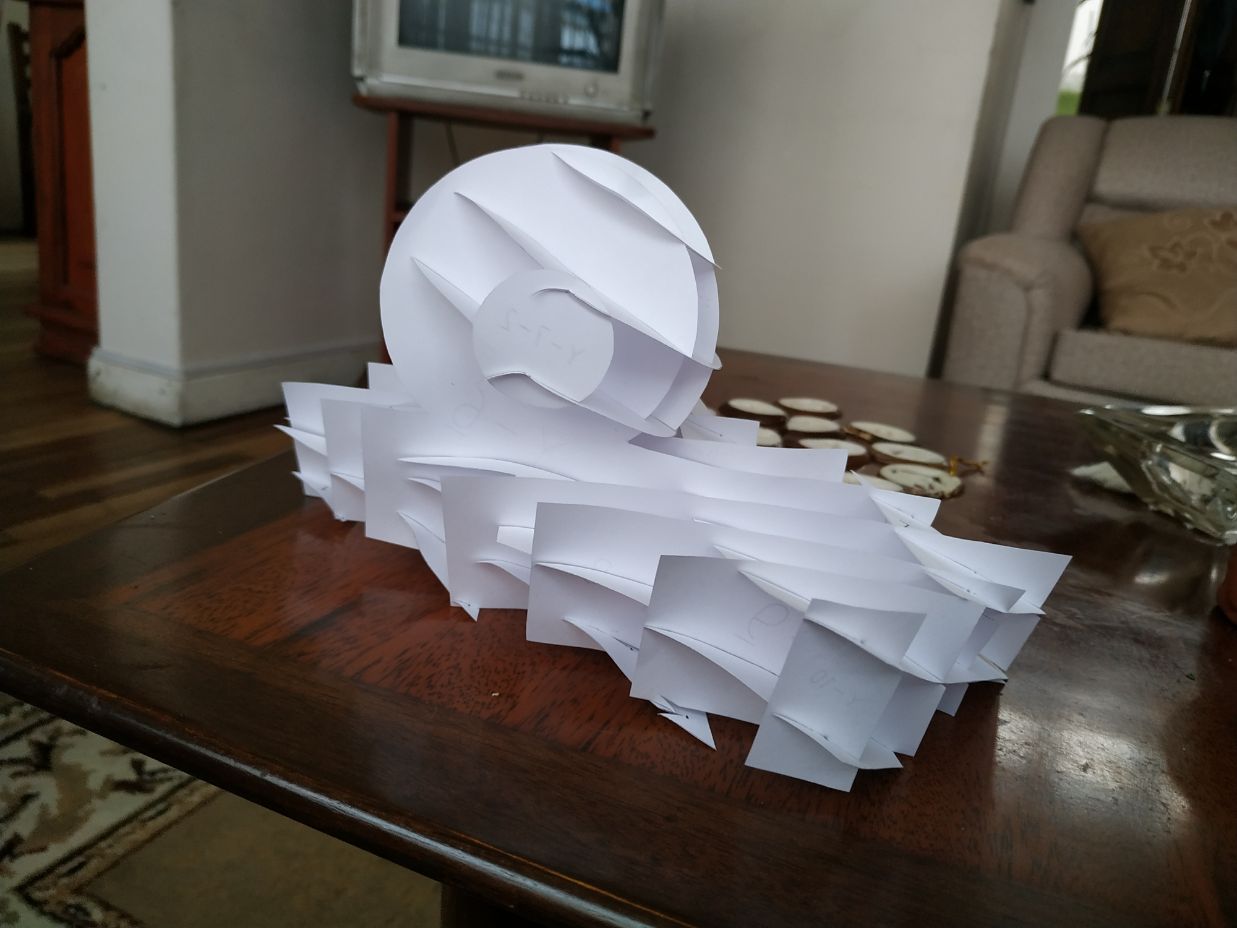
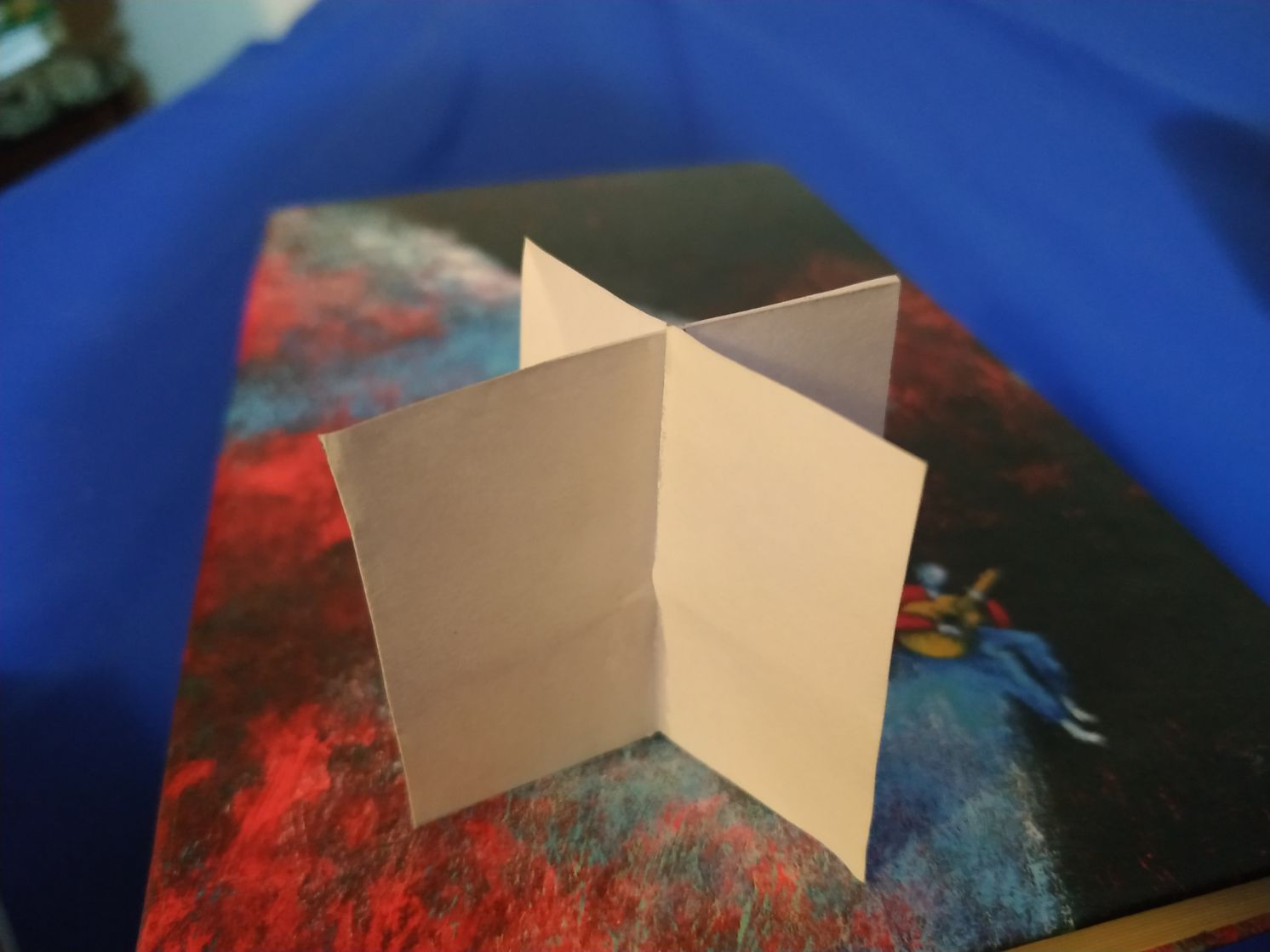
I experimented with some paper (I really like the material) to test the technology in something really thin stuff. I actrually could replicate roughly the shape. The pdf file for manual cutting can be found here.
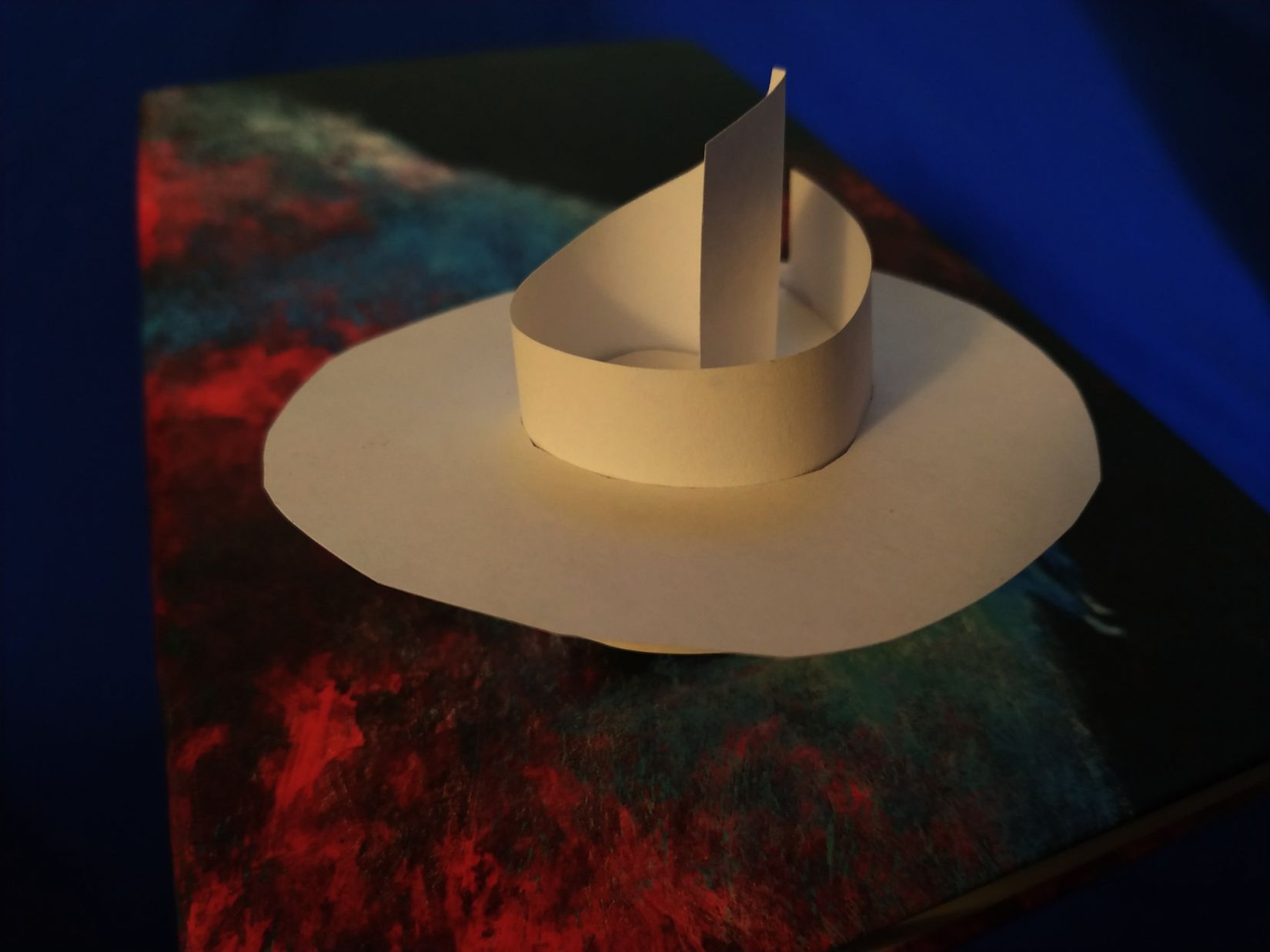
I also tested the lock. With the help of some cyanoacrylate, I obtainded a pretty strong structure. This test were made using paper and sissors, but could be easily digital designed.
Also, playing with the shape of the sloths I have got something like this. Again, a shape suitable to be digitized.
Fabrication
Once we are ready, we could export the files to svg of dxl formats, and edit and organize them using a vector graphics application, as Inkscape.
The files to be cut on cardboard are here.
Assemble
It is possible to follow the instructions given by the Slicer app itself, but I found easier for me to organize the pieces by two groups of Z and Y axis, and each group organized by order. Assembling this project took a little more than 30 minutes, but I think it could be make quicker after a little more experience.
Final result