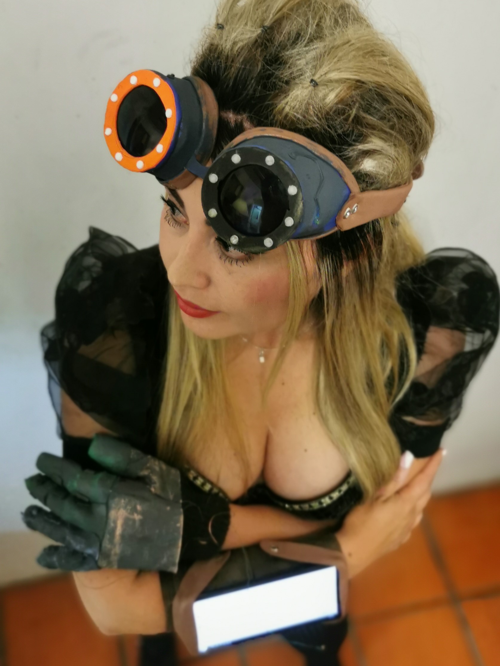
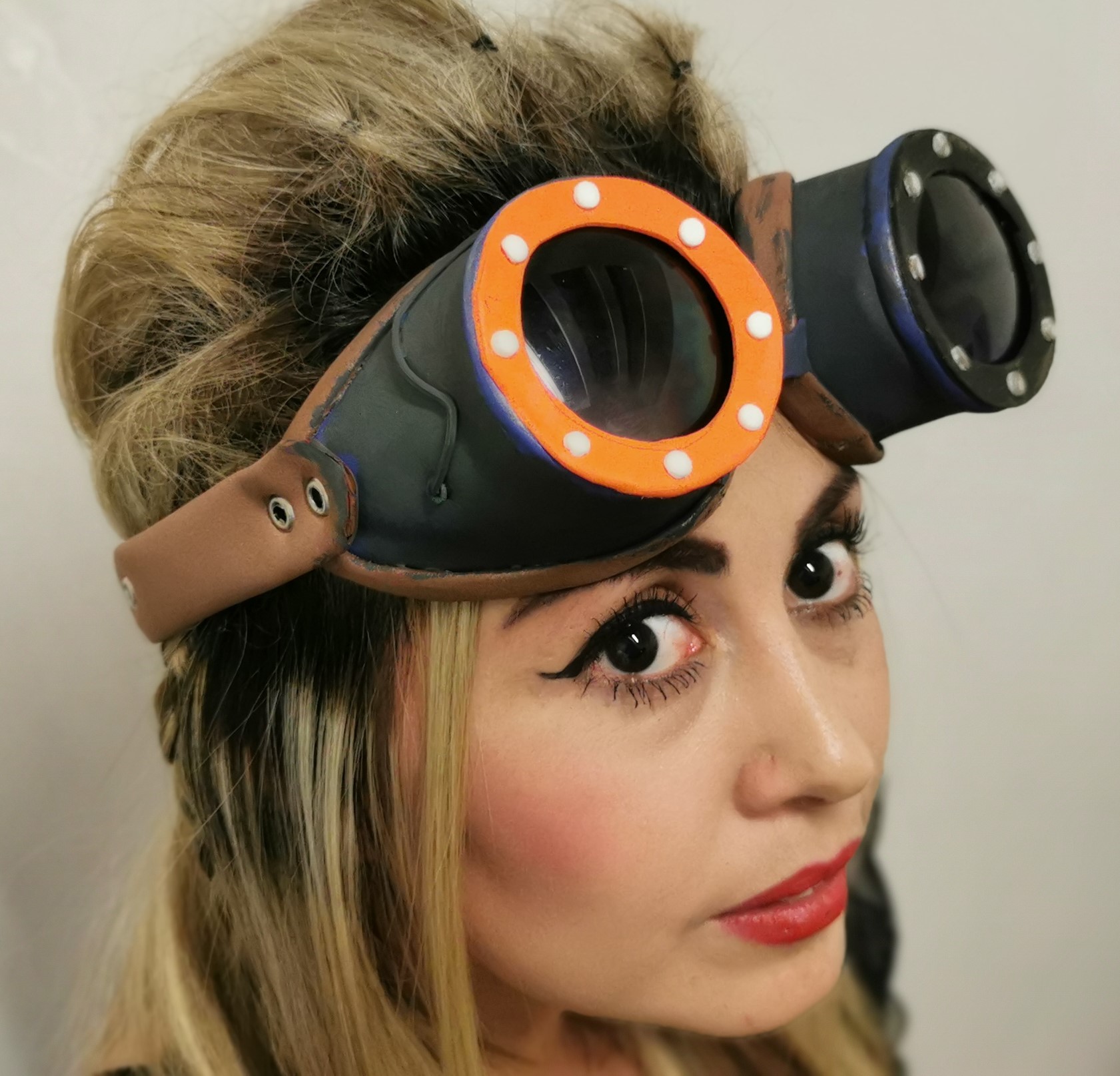
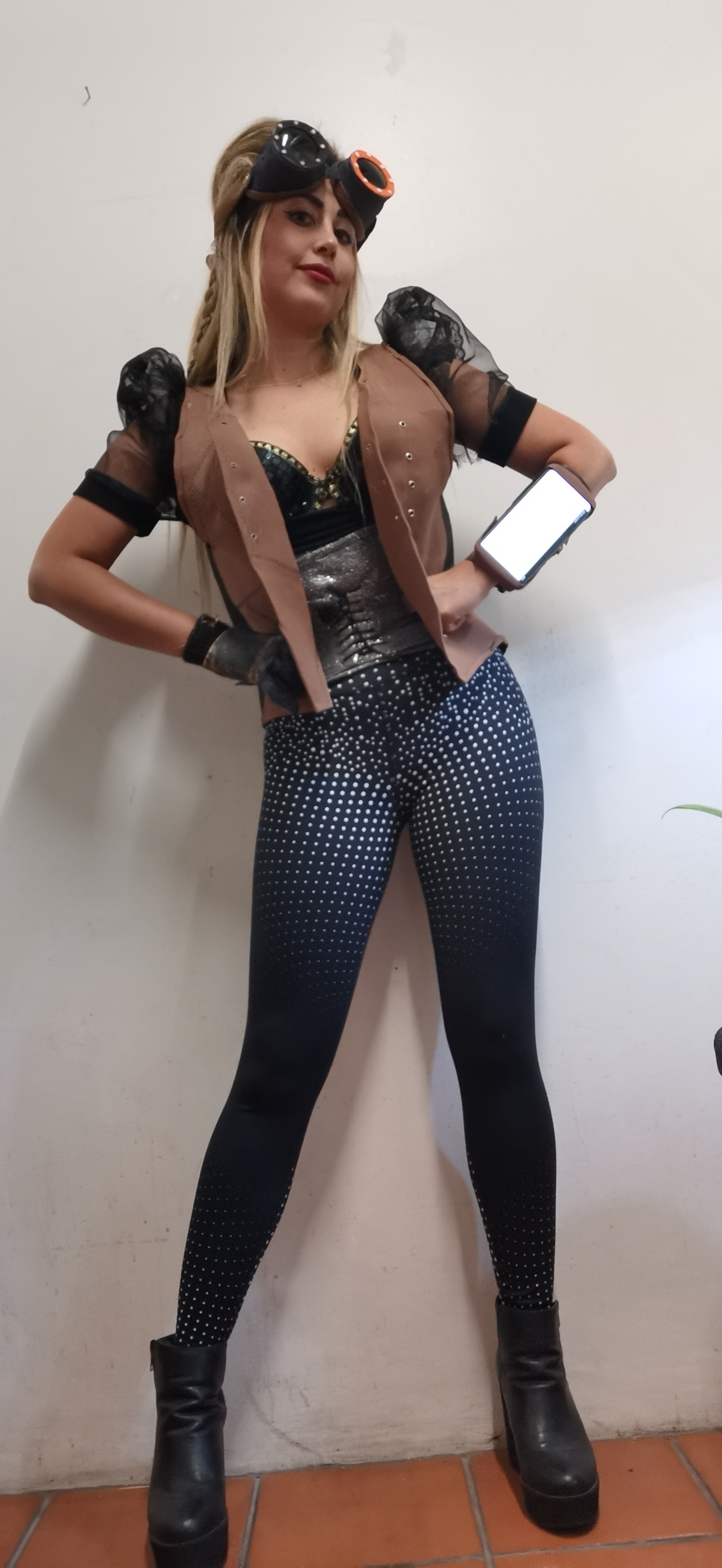
Steampunk MIDI Suit
Perform music with sensors in a cosplay set of gardments.

(I was lucky to be part of de 3D Fashion Week, virtual edition, in Lima, Perú.)
Music control with your clothes
With this project, I wanted to explore the relationship between sound, music, light, and sound modulation and control. My background is mostly in Science and Technology, but for the Fabricademy program the idea of trying something more "artistic" came up.
Nowadays technology allows us to measure a lot of natural phenomena, from temperature to electromagnetic radiation. Data is all around us, and those measurements usually make patterns. Music, on the other hand is also based on patterns. I see music as a communication tool, similar to bird´s singing.
An improvisation using a piezo and a capacitive (touch) sensors. The piezo sensor processes hit and intensity, and is mapped to a single note. The touch sensor is mapped to a sequenser, for tone variation.
It is interesting that electronic communications protocols also follow similar rules (like rhythm/baud rate).
Patterns like the heartbeat can be measured and used for medical applications, but it´s use for music control it´s something that can be explored, like the control of musical parameters, like BPMs.
There is evidence that the music can influence the heartbeat too, so the performer could be -metaphorically- playing with the heart, synchronizing heart speed with music tempo.
Of course, other music synthesis parameters could also be tweaked. Sounds produced by Tap or Flamenco dancers, that use the shoes as percussion instruments could be "digitized", and converted into MIDI signals that trigger samples or synthesized sounds, from gongs to triangles.
This flow of information from analog to digital signals enriches the music, in my view. The other way around, producing analog music from the digital using robots or actuators could add some theatrical touch to the music.
If we are going to use technology, let´s go wireless! After all, 5G is at the corner, and WiFi and other Radio technologies will be faster and more relatable in the near future. This project uses an ESP32 developing board as a brain and sends signals in UDP protocol over WiFi. This chip supports Bluetooth, but the feature is not used in this project.
A computer with WiFi capabilities receives and processes that signal, and converts the OSC messages, and opens one control with mapping potential.
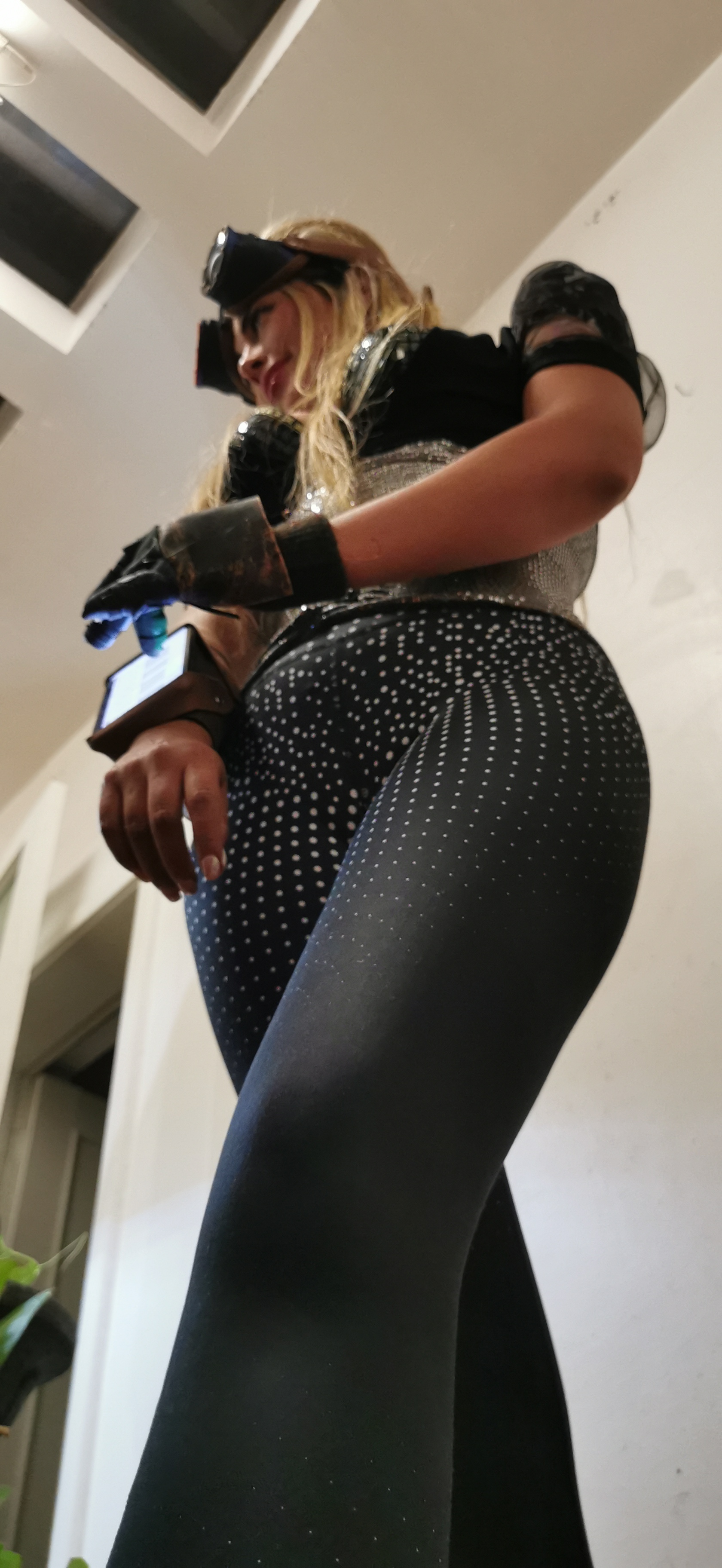
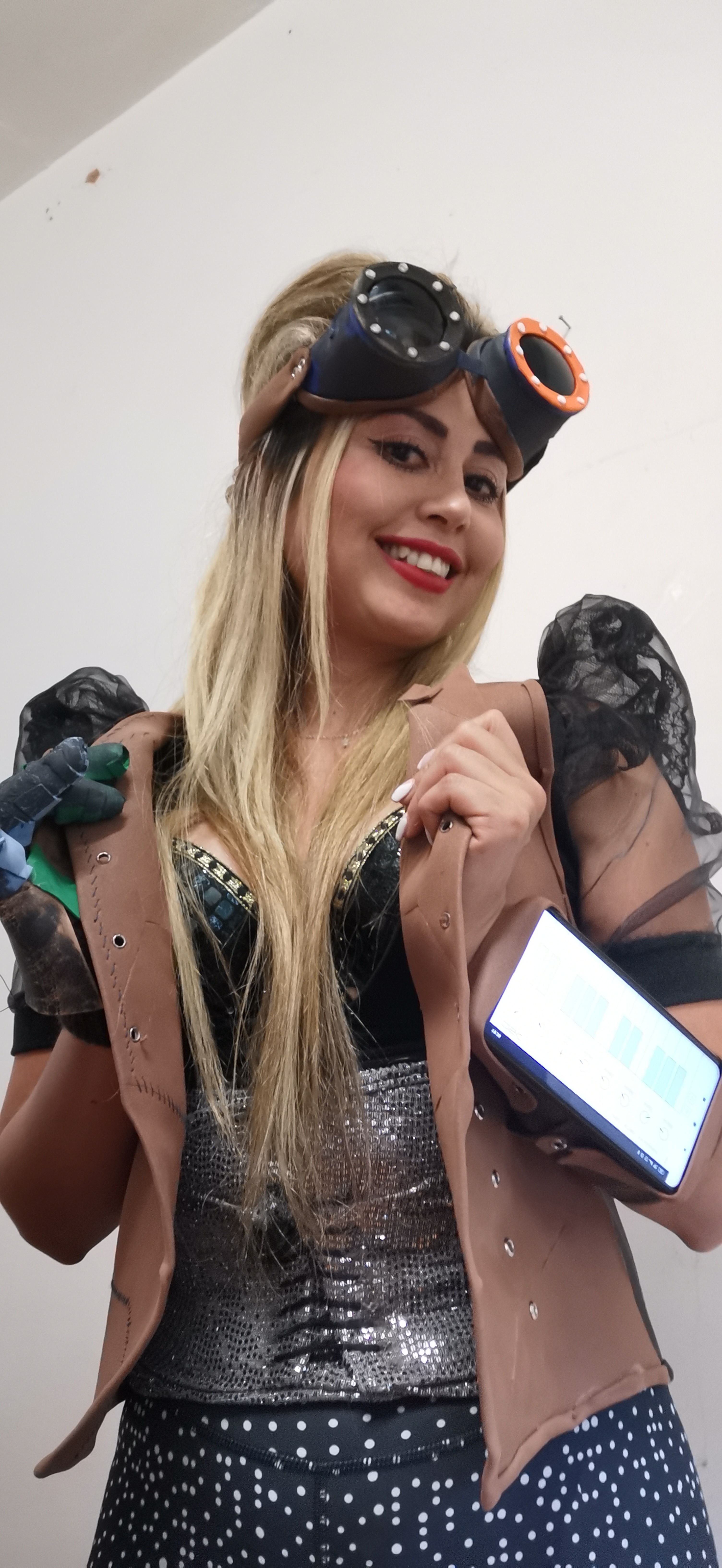
A lot of sensors are embedded in our cell phones, so the idea of integrating a part of it in the garment's options came up during the design. A virtual piano keyboard and other buttons and knobs allow us virtually any number of notes and controls.
Light is also an important part of music performance, and we can control them using Smart LEDs, also known as Neopixels, and a microcontroller. y used an external microcontroller (Arduino) for the lights, so it doesn`t interfere with the music processing duties.
The design of the Suit itself was digitally designed and fabricated. During the pandemic (2019-2020...) a traditional paper/scissors technique was used, but a Cameo 4 with a 3mm blade can be used (saving a lot of time and work) if available.
The design is thought to be user-friendly. The connection to WiFi is set using the auto-connect feature, and the MIDI signal is readable by any DAW (Digital Audio Workstation), as LMMS Linux MultiMedia Studio. The Steampunk community is very inclusive, and having open-source choices is always welcome.
Cloth modeling
Materials
| Qty | Description | Price | Link | Notes |
|---|---|---|---|---|
| 10 | Eva foam sheets | 2.00 $ | local shop | |
| 1 | Material two | 22.00 $ | http://amazon.com/test | |
| 1 | Material three | 22.00 $ | http://amazon.com/test | |
| 1 | Material five | 22.00 $ | http://amazon.com/test | |
| 1 | Material eight | 22.00 $ | http://amazon.com/test | |
| 1 | Material twelve | 22.00 $ | http://amazon.com/test | |
| 1 | Material eleven | 22.00 $ | http://amazon.com/test |
Useful links
MIDI control test
Accelerometer test - AndyMoon from David Arias on Vimeo.
Code Example
Use the three backticks to separate code.
/*---------------------------------------------------------------------------------------------
  Open Sound Control (OSC) library for the ESP8266/ESP32
  Example for sending messages from the ESP8266/ESP32 to a remote computer
  The example is sending "hello, osc." to the address "/test".
  This example code is in the public domain.
--------------------------------------------------------------------------------------------- */
//#if defined(ESP8266)
//#include <ESP8266WiFi.h>
//#include <DNSServer.h>
//#include <ESP8266WebServer.h>
#include <WiFiManager.h>
//#else
//#include <WiFi.h>
//#endif

//#if defined(ARDUINO_ARCH_ESP8266)
//#include <ESP8266WiFi.h>
//#include <ESP8266WebServer.h>
//#elif defined(ARDUINO_ARCH_ESP32)
//#include <WiFi.h>
//#include <WebServer.h>
//#endif
//#include <time.h>
//#include <AutoConnect.h>

//#if defined(ARDUINO_ARCH_ESP8266)
//ESP8266WebServer Server;
//#elif defined(ARDUINO_ARCH_ESP32)
//WebServer Server;
//#endif

//AutoConnect       Portal(Server);
//AutoConnectConfig Config;       // Enable autoReconnect supported on v0.9.4

#include <WiFiUdp.h>
#include <OSCMessage.h>

//char ssid[] = "yournetwork";          // your network SSID (name)
//char pass[] = "yourpassword";                    // your network password

WiFiUDP Udp;                                // A UDP instance to let us send and receive packets over UDP
const IPAddress outIp(192,168,1,119);        // remote IP of your computer 192.168.1.104
const unsigned int outPort = 9090;          // remote port to receive OSC
const unsigned int localPort = 8888;        // local port to listen for OSC packets (actually not used for sending)

int signalp = 0;
int signal2 = 0;
int signal3 = 0;
int maxsignal = 0;
int minsignal = 100;
int maxsignal2 = 0;
int minsignal2 = 100;
int maxsignal3 = 0;
int minsignal3 = 100;

int heartPulse = 35;
int heartPulseReading = 0;

int piezo1 = 34;
int signalpiezo = 0;
int maxsignalP;
int minsignalP;

int piezoSensitivity = 30;

//int PulseSensorPurplePin = 21;        // Pulse Sensor PURPLE WIRE connected to ANALOG PIN 26
int Signal;
int Threshold = 90;

void setup() {

    pinMode(piezo1, INPUT);
    pinMode(heartPulse, INPUT);

     WiFi.mode(WIFI_STA); // explicitly set mode, esp defaults to STA+AP

    Serial.begin(115200);

    WiFiManager wm;

    // Connect to WiFi network
 //   WiFiManager wifiManager;
 //   Serial.println("Conecting.....");
//    wifiManager.autoConnect("MIDI Suit", "12345");
//    Serial.println("connected");
 //   Serial.println();
 //   Serial.println();
 //   Serial.print("Connecting to ");
 //   Serial.println(ssid);
 //   WiFi.begin(ssid, pass);

 //   while (WiFi.status() != WL_CONNECTED) {
 //       delay(500);
 //       Serial.print(".");
 //   }
 //   Serial.println("");

 //   Serial.println("WiFi connected");
 //   Serial.println("IP address: ");
 //   Serial.println(WiFi.localIP());

 //   Serial.println("Starting UDP");
 //   Udp.begin(localPort);
 //   Serial.print("Local port: ");
//#ifdef ESP32
 //   Serial.println(localPort);
//#else
//    Serial.println(Udp.localPort());
//#endif

 bool res;
    // res = wm.autoConnect(); // auto generated AP name from chipid
    // res = wm.autoConnect("AutoConnectAP"); // anonymous ap
    res = wm.autoConnect("AutoConnectAP","password"); // password protected ap

    if(!res) {
        Serial.println("Failed to connect");
        // ESP.restart();
    }
    else {
        //if you get here you have connected to the WiFi
        Serial.println("connected...yeey :)");
    }


}

void loop() {
  /*
    signalp = touchRead(4);
    delay(5);
    signal2 = touchRead(15);
    delay(5);
    signal3 = touchRead(13);
    delay(5);

    heartPulseReading = analogRead(heartPulse);
    delay(5);
    signalpiezo = analogRead(piezo1);

if (signal3 > maxsignal3){
    maxsignal3 = signal3;
  }
  else {
    maxsignal3 = maxsignal3;
  }

  if (signal3 < minsignal3){
    minsignal3 = signal3;
  }
  else {
    minsignal3 = minsignal3;
  }

//----------

if (signal2 > maxsignal2){
    maxsignal2 = signal2;
  }
  else {
    maxsignal2 = maxsignal2;
  }

  if (signal2 < minsignal2){
    minsignal2 = signal2;
  }
  else {
    minsignal2 = minsignal2;
  }

//----------

  if (signalp > maxsignal){
    maxsignal = signalp;
  }
  else {
    maxsignal = maxsignal;
  }

  if (signalp < minsignal){
    minsignal = signalp;
  }
  else {
    minsignal = minsignal;
  }

//----------

if (signalpiezo > maxsignalP){
    maxsignalP = signalpiezo;
  }
  else {
    maxsignalP = maxsignalP;
  }

  if (signalpiezo < minsignalP){
    minsignalP = signalpiezo;
  }
  else {
    minsignalP = minsignalP;
  }


  signalp = map(signalp, maxsignal, minsignal, 0, 127);
  signal2 = map(signal2, maxsignal2, minsignal2, 0, 127);
  signal3 = map(signal3, maxsignal3, minsignal3, 0, 127);

  signalpiezo = map(signalpiezo, maxsignalP, minsignalP, 127, 0); //reverse mapping.

if (signalpiezo > 30){

    OSCMessage msg1("/piezo1");
    msg1.add(signalpiezo);
    Udp.beginPacket(outIp, outPort);
    msg1.send(Udp);
    Udp.endPacket();
    msg1.empty();
}

if (signal3 > 30){

    OSCMessage msg3("/touch3");
    msg3.add(signal3);
    Udp.beginPacket(outIp, outPort);
    msg3.send(Udp);
    Udp.endPacket();
    msg3.empty();
}

if (signalp > 30){

    OSCMessage msg("/touch1");
    msg.add(signalp);
    Udp.beginPacket(outIp, outPort);
    msg.send(Udp);
    Udp.endPacket();
    msg.empty();
}

if (signal2 > 30){

    OSCMessage msg2("/touch2");
    msg2.add(signal2);
    Udp.beginPacket(outIp, outPort);
    msg2.send(Udp);
    Udp.endPacket();
    msg2.empty();
}

heartPulseReading = map(heartPulseReading, 0, 3000, 0, 127);

Serial.println(heartPulseReading);

//Signal = analogRead(PulseSensorPurplePin);

//Serial.println(Signal);

//if(Signal > Threshold){                          // If the signal is above "550", then "turn-on" Arduino's on-Board LED.
if(heartPulseReading > Threshold && heartPulseReading < (Threshold + 40)){
    // digitalWrite(LED13,HIGH);
    OSCMessage msg2("/heart");
    msg2.add(heartPulseReading);
    Udp.beginPacket(outIp, outPort);
    msg2.send(Udp);
    Udp.endPacket();
    msg2.empty();
   } else {
    // digitalWrite(LED13,LOW);                //  Else, the sigal must be below "550", so "turn-off" this LED.
   }

*/

    delay(100);
}
The script takes signals (piezo, touch, hear pulse sensor, etc.) and map them to notes MIDI signals or control MIDI signals (cc). To send them to the computer for music crafting we need a couple of programs.
A newer file, showing different connections can be downladed here.
First, we need to stablish a connection with the ESP32 module. It is important that both the computer and the module are connected to the same network.
Once both are connected (with the same ip address in the script and computer connection), we configure the device.
This is done opening the connection manager of the computer.
For a virtual MIDI port, I used (loopMIDI)[https://www.tobias-erichsen.de/software/loopmidi.html], from Tobias Erichsen, but any virtual MIDI port would do (this one is for windows 10).
In Pd Extended, configure it to read from de MIDI port (you have to create one). I created one called "Suit".
First, we need software to detect MIDI signals. We use (Pure Data Extended)[https://puredata.info/downloads/pd-extended] for this porpouse. Once you have it, you can open this file".
Gallery


Video
@wavewmusic Steampunk MIDI suit
♬ F Boy - Ander Huang & DJ Kuromi
3D Models
Video (in Spanish), for the 3D Fashion Week
MIDI Suit Steampunk Style from WaveW on Vimeo.