5. E-Textiles and Wearables I
This week we are going to explore the field of digital technology and gardments. We are going to dive into Embeded chips, specifically programable microcontrollers, and the interfase between hard and soft electronics.
Video
Here we can see the interaction of the touch sensor (capacitance based), it´s readings and the use of this information to actuate a tone in a buzzer. We can see the change in the notes sequence and also the readings of the other sensors in the background screen.
Desing
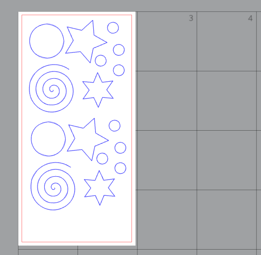
First design insert a few shapes in a vector graphic program. I used Inskcape.

Then, the saved PNG file could be saved also as dfx. Importing it to Silouette Studio, the native program for the machine vinyl cutter.
Here, we can set the width of the copper sheet and arrange the objects.
Electronics
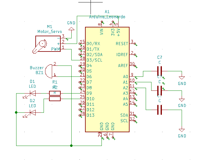
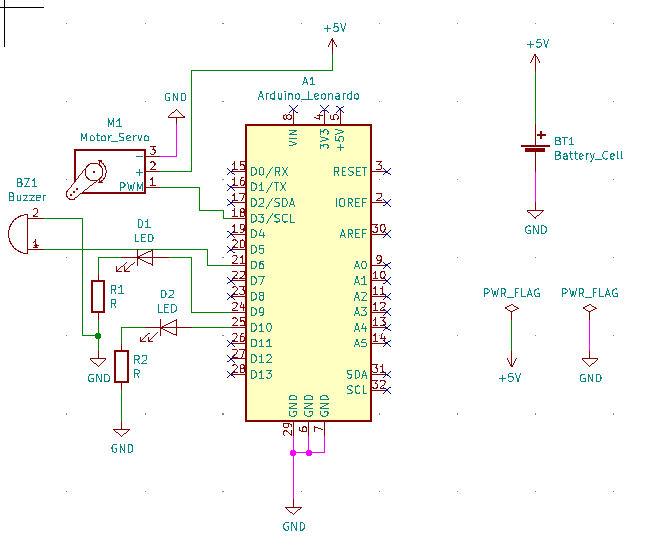
I used Kicad for the representation of the circuit. The arduino, two leds, the buzzer, a servo and the capacitive sensors, represented as the tree capacitors. In the system capacitor/GND, you (the toucher) is the ground part of the capacitor.
In order to check the integrity of the circuit, we need to annotate (name) the components of the circuit.
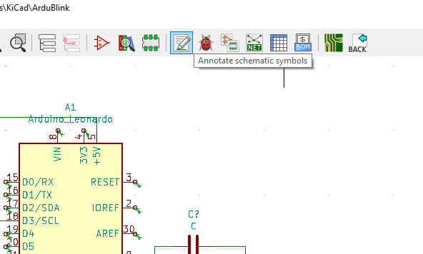
We see a question mark... we need to annote at this point.
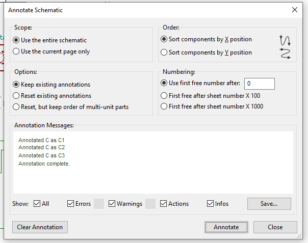
Annotated, we can see that each one has it´s name.
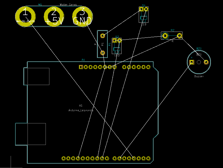
Done with the schematics, we move to the board design. We´ll do this just for testing the program. At the end the connection could be done directlly form the board.
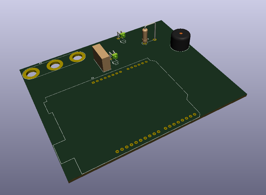
We can also see and export the PCB as a 3D object. Nice.
Latter we can use it in a FreeCad easily.
You can check the files used here in the following links:
Vector graphics document. DXF Copper Swatch DXF. Vector graphics document. SVG Copper Swatch SVG. Silouette software Copper Swatch .studio3. Circuit Files (KiCad) Rar file.
Fabrication
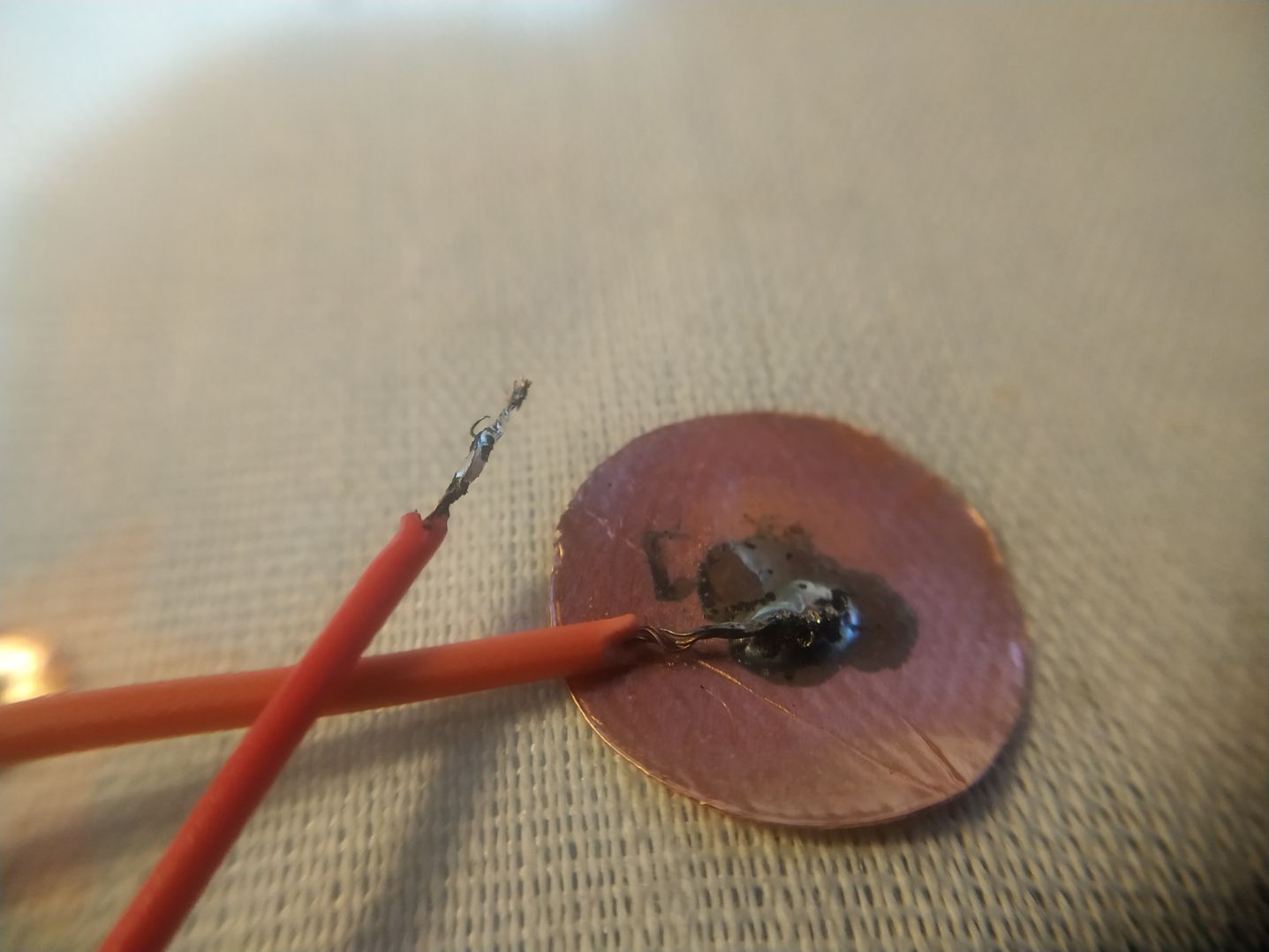
For soldering, it is useful to do a pre-tinning of the copper pieces we are going to solder. This makes the job a lot easier.
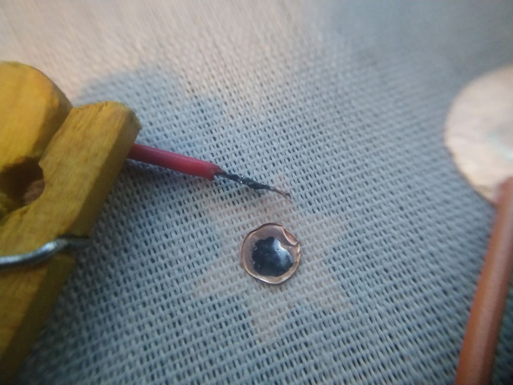
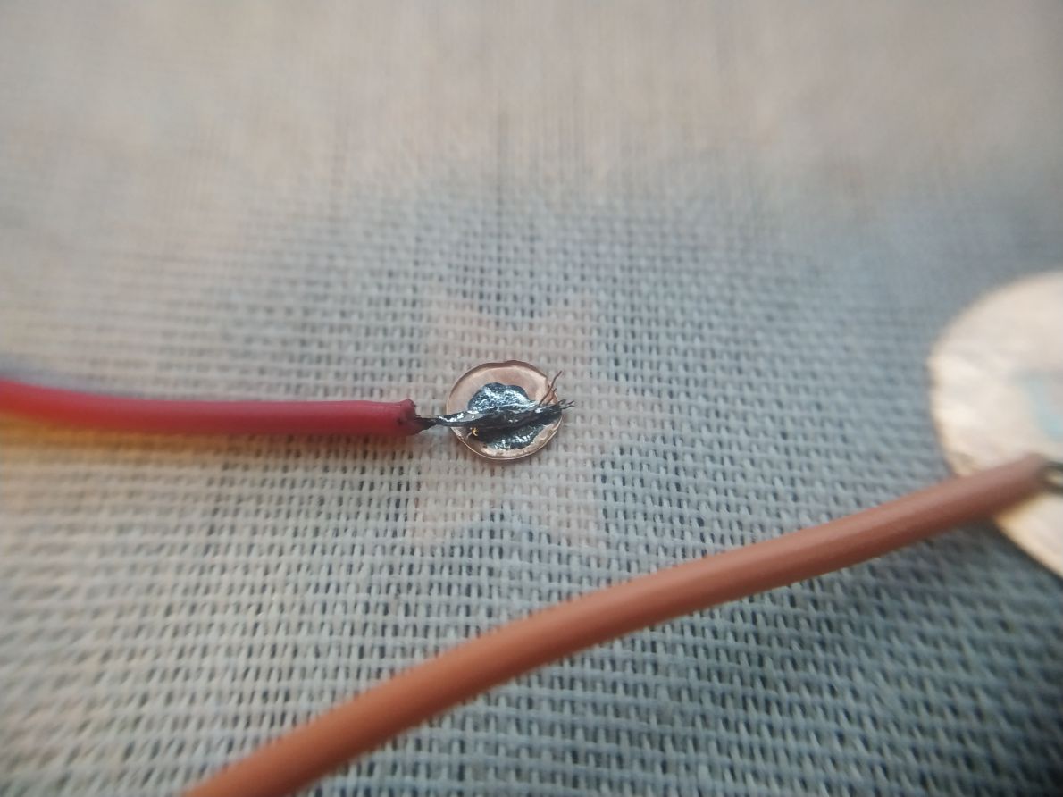
Here we can see the two surfaces soldered together. It is important to have a solid and shinny soldering point, to assure conductivity and avoid cold-soldering.
The use of soldering flux reduces oxidation of the melted tin alloy. We have to remember that the soldering wire contains lead (unless stated otherwise), that could be toxic and bio-acummulative, so be carfull in using this material in cases where this could get into biological organisms (as us).
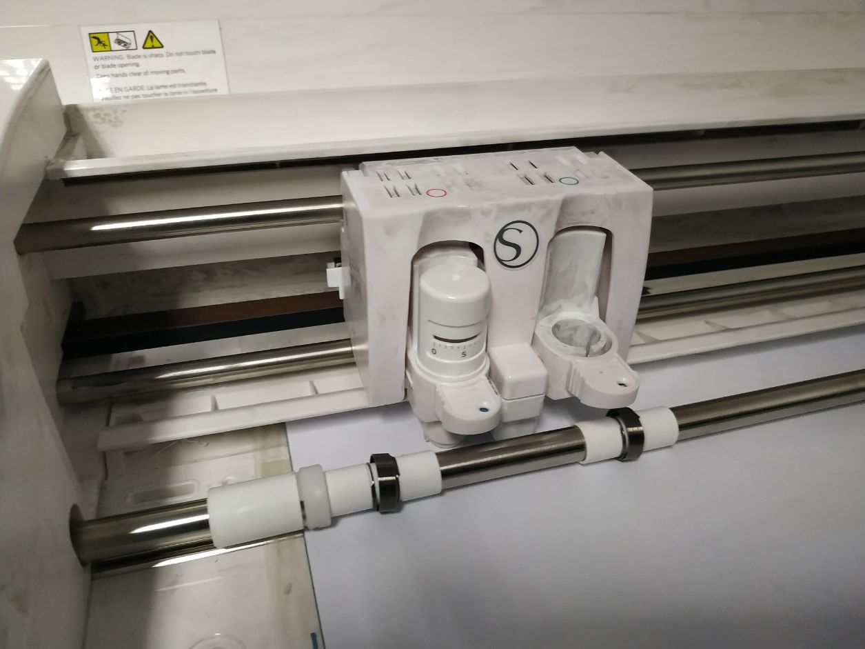
The machine, loaded and ready to work.
A good soldering "wets" the material that is soldered. Once solid, it still reminds a drop of fluid, including the surface tension asositated with liquids like water.
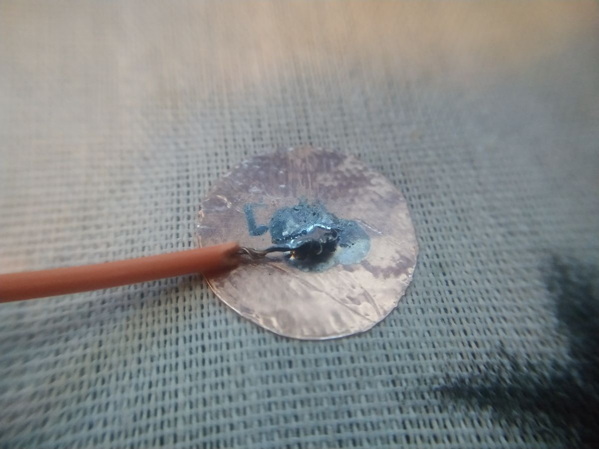
Preassuring the auto-adhesive copper foil agains the fabric imprints the pattern to the metal. Still, this system looks better for non-stretching gardments and fabrics, as the metal looses it`s adhesion with flexible and stretchable materials.
If we see it a little closer, we can see the fabric´s pattern on the copper.

Here is the soldering point completed. The wire is hidden inside the solder.
Here is the result from the cutting machine. The setting still need to be improved.
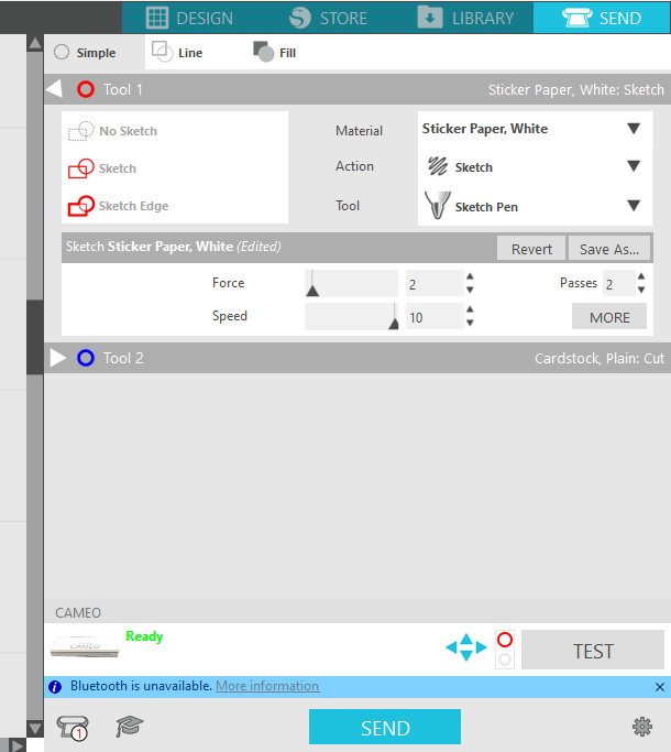
Cutting settings.
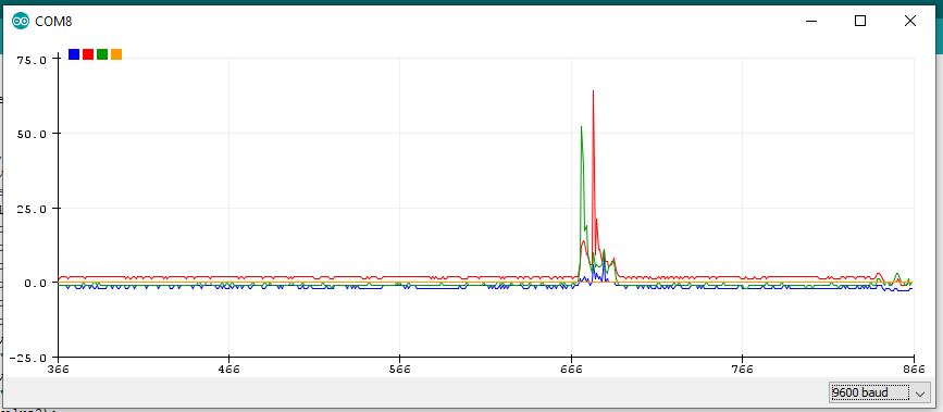
Sensor readings. Blue, red and green are the connected sensors. We can see that the change is changes with the surface of the touching sensor.
Cutting settings, speed changed to 10.
Code
Here is the code used. It is commented.
Basically, takes the value from the sensor(s) and use it for chaging the notes sequence, the light intensity and the position of the servo. It is important to note that, for using lots of leds, servos, and actuators in general would require external power and maybe transistors and/or relays.
I found this interesting library called ADCTouch. You need to install it first to make this code work.
    #include <ADCTouch.h>
    #include <Servo.h>

    Servo myservo;  // create servo object to control a servo

    int ref0, ref1, ref2;       //reference values to remove offset
    int maxVal;
    int maxVal1;
    int minVal;
    int minVal1;
    int ligthIntensity;
    int ledPin = 9;
    int buzzer = 6;
    int audFrecuency;
    // int motor = 4; //uncheck to use a signal for a motor.
    int ledPin1 = 10;
    int intervalControl;
    int intervalControlBeat;
    int val;

    void setup()
    {
        // No pins to setup, pins can still be used regularly, although it will affect readings

        Serial.begin(9600);
        pinMode(buzzer, OUTPUT);
        pinMode(motor, OUTPUT);
        ref0 = ADCTouch.read(A0, 500);    //create reference values to
        ref1 = ADCTouch.read(A1, 500);      //account for the capacitance of the pad
        ref2 = ADCTouch.read(A2, 500);      //account for the capacitance of the pad
        myservo.attach(3);
    }

    void loop()
    {
        int value0 = ADCTouch.read(A0);   //no second parameter
        delay(10);
        int value1 = ADCTouch.read(A1);     //   --> 100 samples
        delay(10);
        int value2 = ADCTouch.read(A2);     //   --> 100 samples
        delay(10);
        //int valueInt1 = ADCTouch.read(A2);
        //delay(20);
        //int valueInt2 = ADCTouch.read(A2);
        //delay(20);
        //int valueInt3 = ADCTouch.read(A2);
        //delay(20);
        //int value2 = (valueInt1 + valueInt2 + valueInt3) / 3;

        value0 -= ref0;       //remove offset
        value1 -= ref1;
        value2 -= ref2;

        if(maxVal < value2){
          maxVal = value2;
        }
        else{
          maxVal = maxVal;
        }
        if(minVal > value2){
          minVal = value2;
        }
        else{
          minVal = minVal;
        }

        if(minVal < 0){
          minVal = 0;
        }
        else{
          minVal = minVal;
        }

        // other pin

        if(maxVal1 < value1){
          maxVal1 = value1;
        }
        else{
          maxVal1 = maxVal;
        }
        if(minVal1 > value1){
          minVal1 = value1;
        }
        else{
          minVal1 = minVal1;
        }

        if(minVal1 < 0){
          minVal1 = 0;
        }
        else{
          minVal1 = minVal1;
        }

        ligthIntensity = map(value2, minVal, maxVal, 0, 255);
        intervalControl = map(value1, minVal1, maxVal1, 0, 255);
        intervalControlBeat = map(value1, minVal1, maxVal1, 100, 600);
        //val = analogRead(value2);            // reads the value of the potentiometer (value between 0 and 1023)
        val = map(value2, minVal, maxVal, 10, 165);     // scale it to use it with the servo (value between 0 and 180)

        //analogWrite(ledPin1, ligthIntensity);
        digitalWrite(motor, HIGH);
        myservo.write(val);
        delay(50);
        //audFrecuency = map(value2, minVal, maxVal, 20, 20000);
        //audFrecuency = map(value2, minVal, maxVal, 10, 1000);
        audFrecuency = map(value2, minVal, maxVal, 40, 4000);
        //delay(200);
        //tone(buzzer,1000); //1KHz sound signal audFrecuency

        if(ligthIntensity > 10){
          tone(buzzer,audFrecuency);
          analogWrite(ledPin, ligthIntensity);
          delay(10);
        }
        else{
          noTone(buzzer);
        }

        // Feel free to uncomment to get different readings.
        //tone(buzzer,audFrecuency); //1KHz sound signal
        //delay(intervalControlBeat);
        //noTone(buzzer);
        delay(intervalControlBeat);
        //Serial.print(value0 > 40);    //return pressed or not pressed
        //Serial.print("\t");
        //Serial.print(value1 > 40);
        //Serial.print("\t\t");
        //Serial.print(value2 > 40);
        //Serial.print("\t\t");
        Serial.print(value0);             //return value
        Serial.print("\t");
        Serial.print(value1);
        Serial.print("\t");
        Serial.print(value2);
        Serial.print("\t");
        //Serial.print(maxVal1);
        //Serial.print("\t");
        Serial.println(minVal);
        //Serial.print("\t");
        //Serial.println(ligthIntensity);
        //Serial.print("\t");
        delay(100);
    }