12. Soft robotics
In this class we are going to explore the new fields of using soft materials as sensors and actuators.
I think the field of soft robotics have a really interesting future in biothechnogy too. They are making plans to use them in space exploration, as seen in the following video.
Design
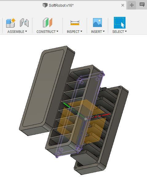
We are going to start by designing a mold for our soft material.
The design consist in tree pieces, the one at the top is for the second cast. The other two are assembled together for the first casting.
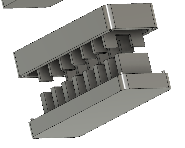
These are the parts used for the first casting.
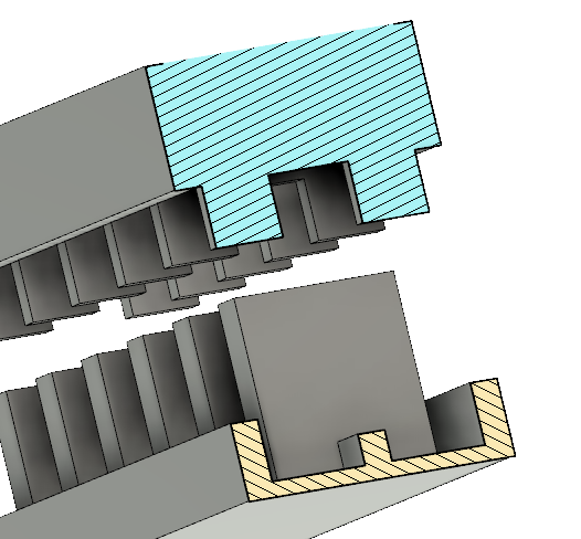
Here we see a cut.
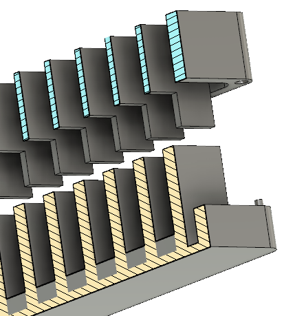
A cut in other direction.
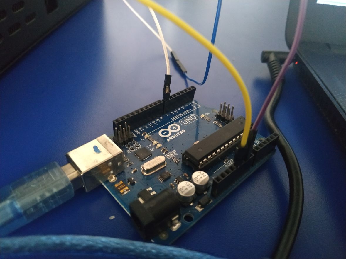
Tree conection for generatin a blik signal.
Fabrication
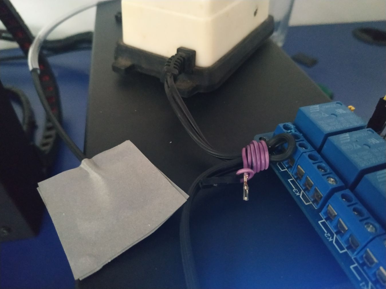
Cut for the relay.
Relay installed.
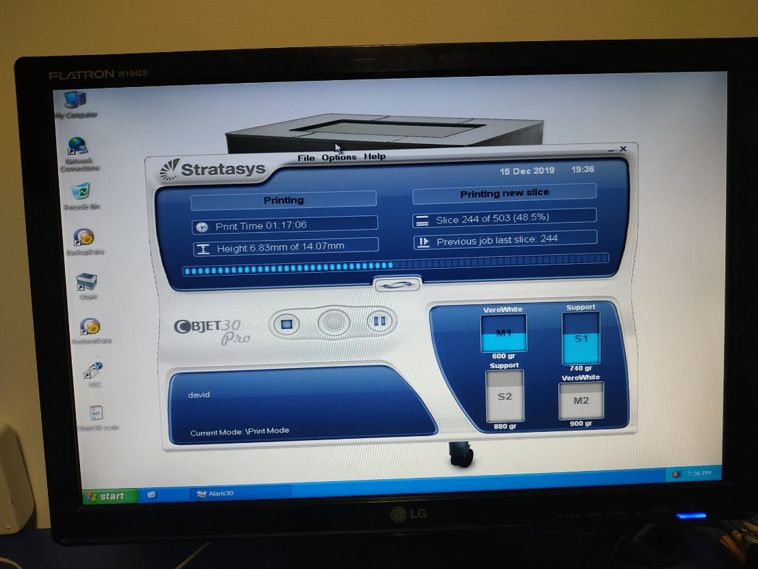
Advance on the Statasys system printing.
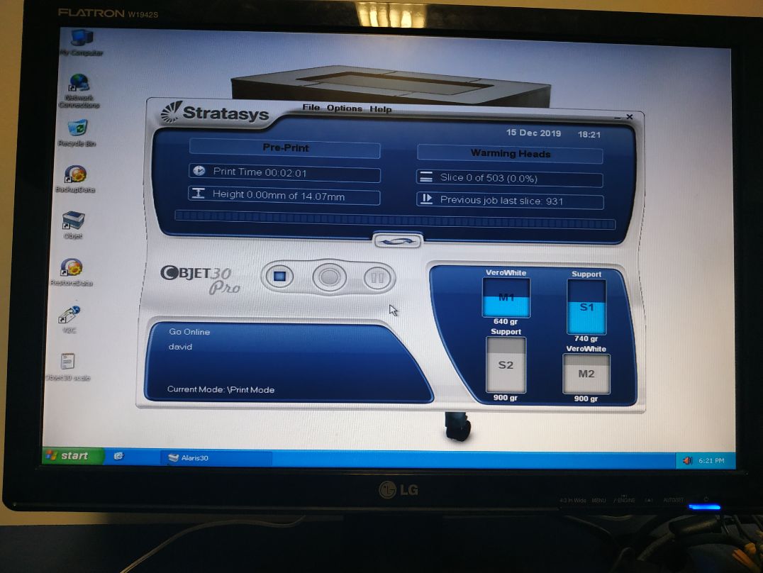
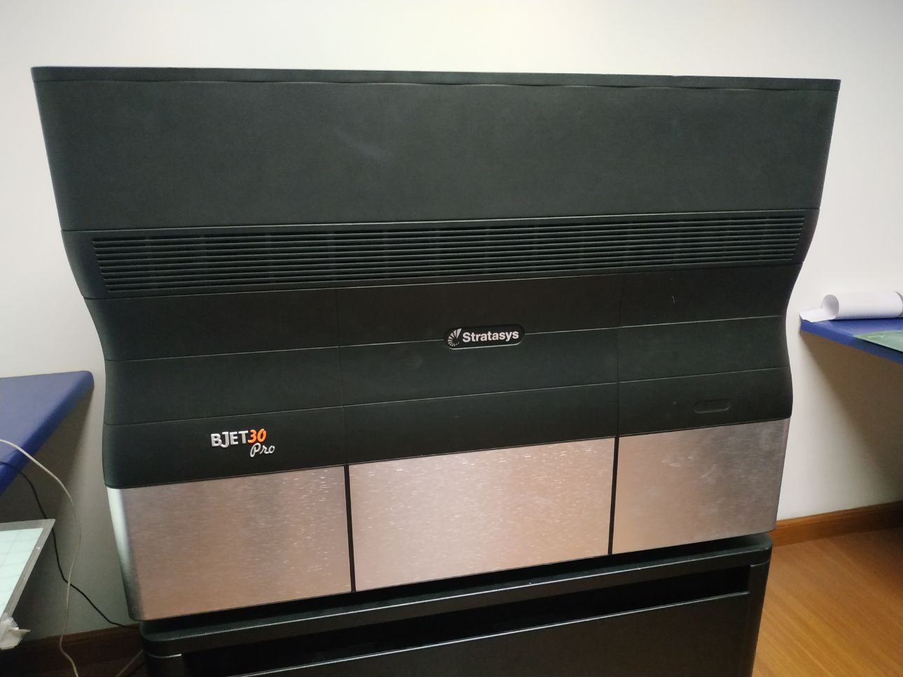
The machine.
48% ...
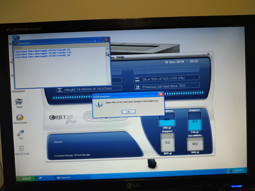
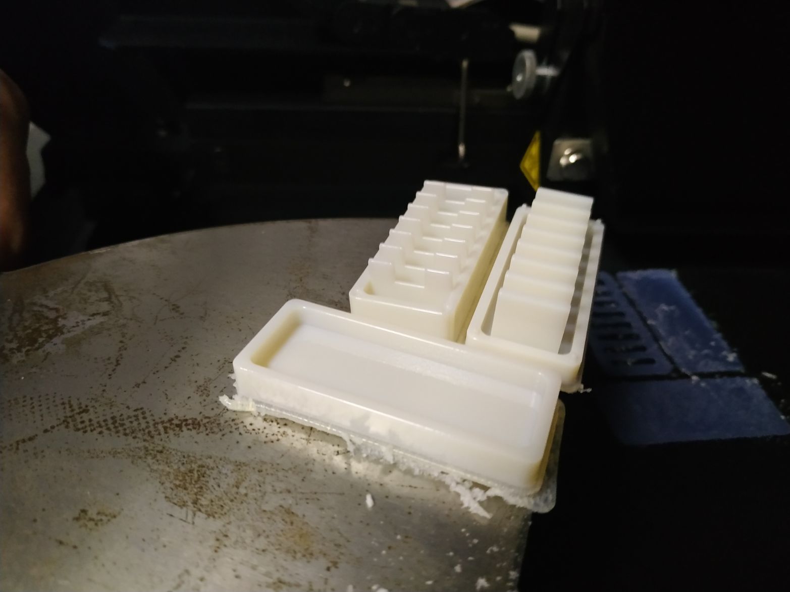
Finally done.
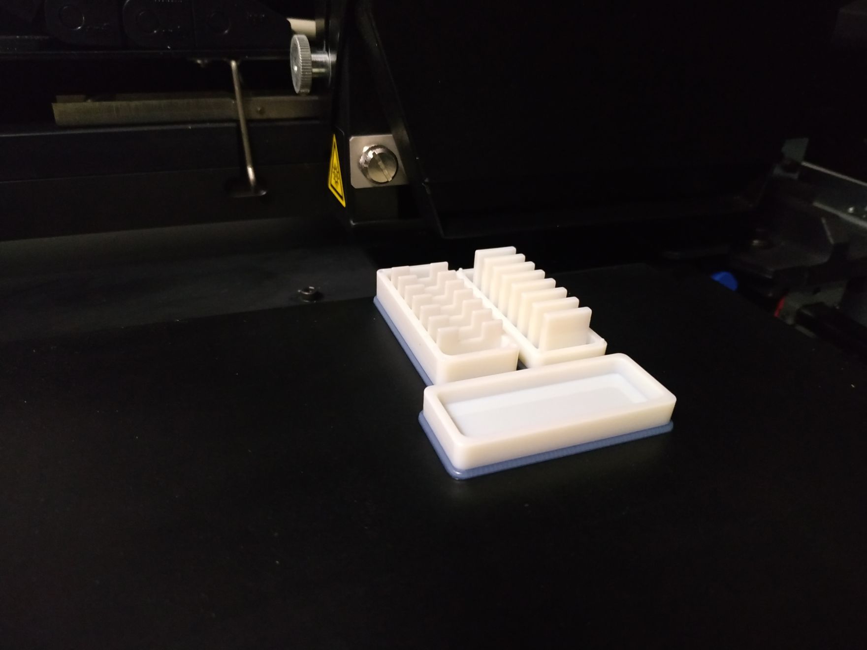
The result.
With a hand, for perspective.
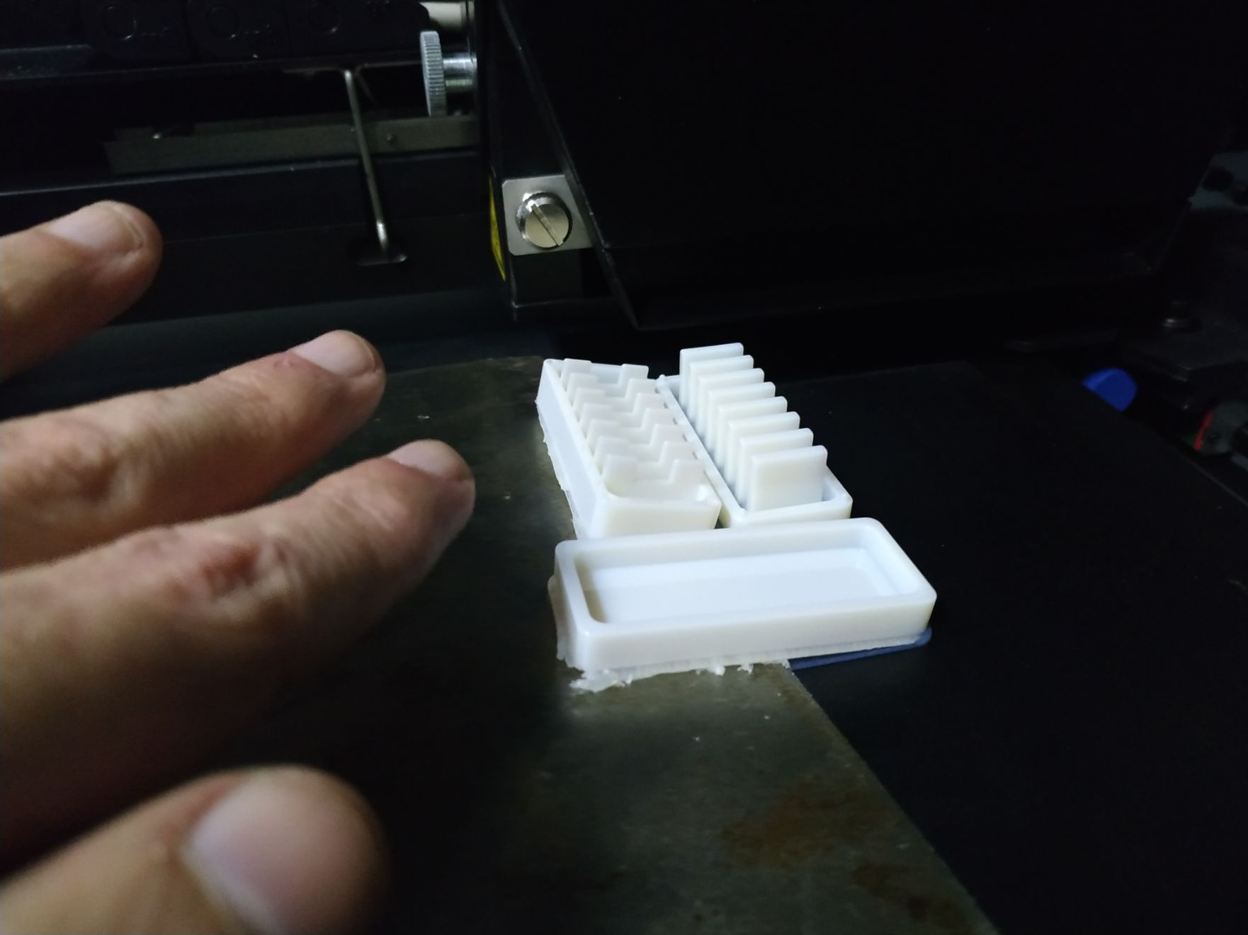
The pieces need a little clean up. The printing came out with a little bit of supporting material.
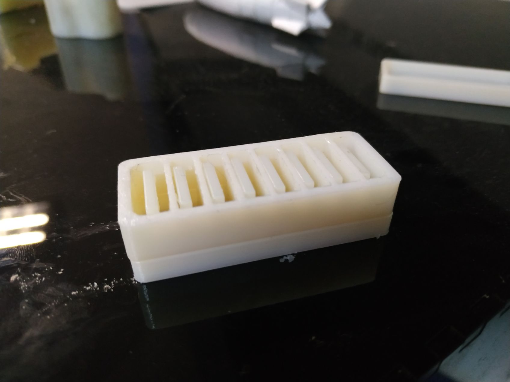
Pieces clean.
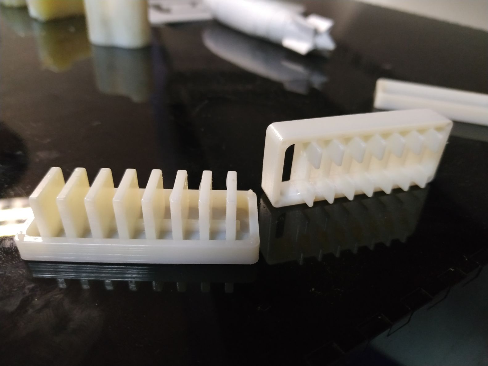
Pieces clean and assembled.
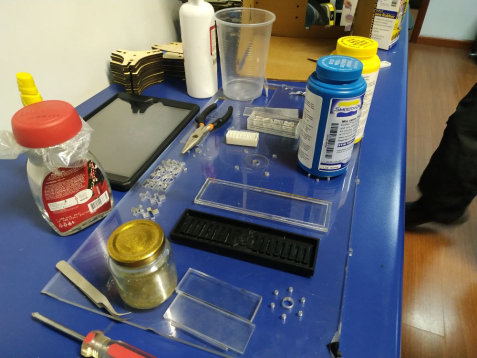
Workbench ready for the casting.
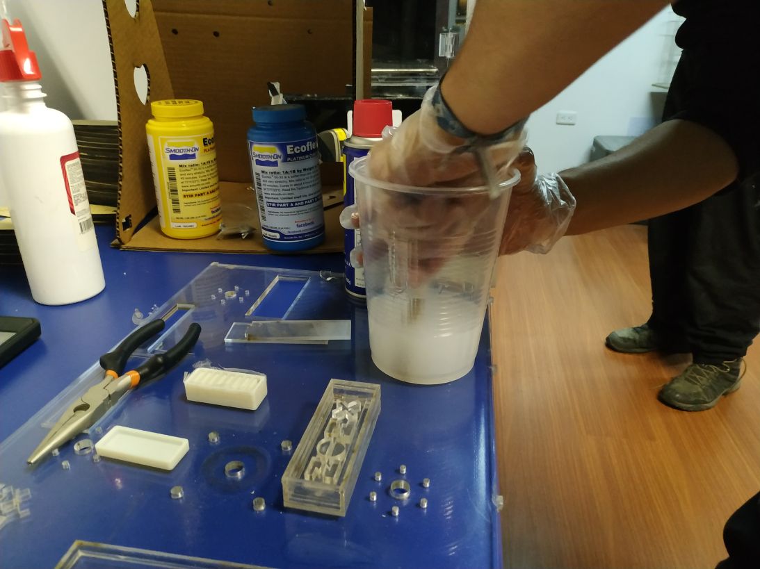
First the mix.
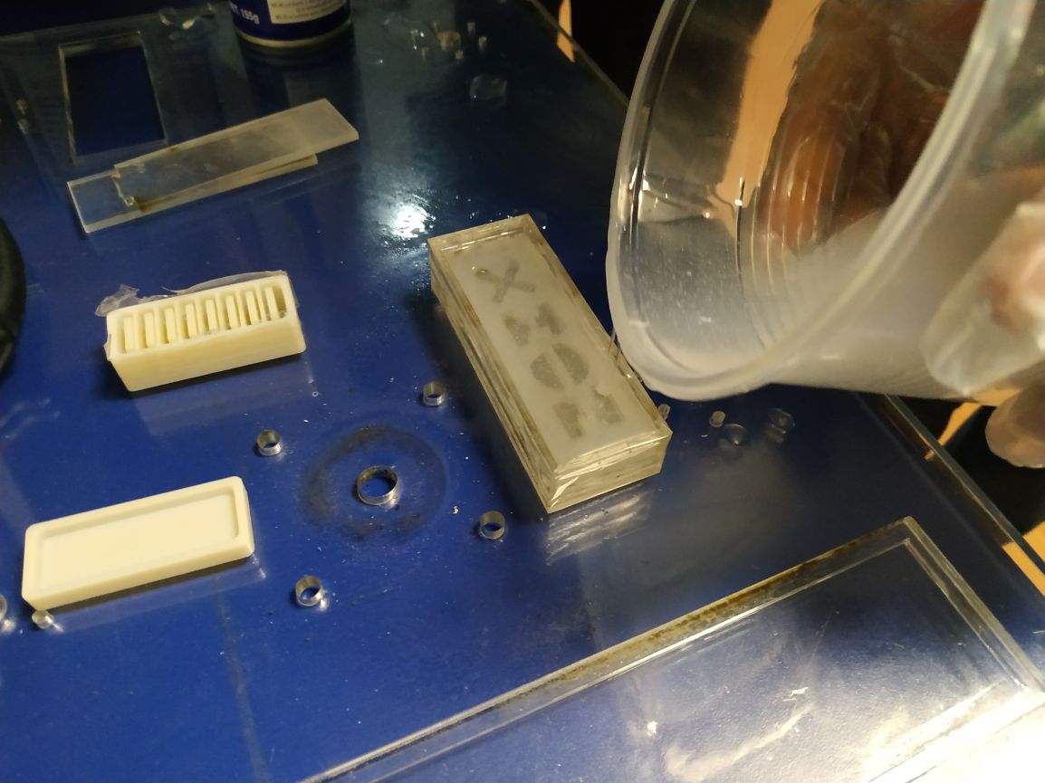
Then the poruring.
A little too much. Some got spilled.
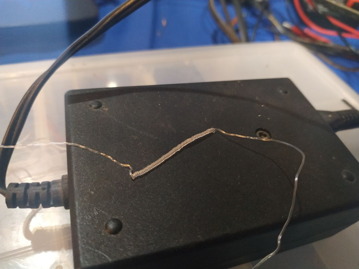
Test with artificial musclules
Material used: Polyamide, 0.40 mm wide.
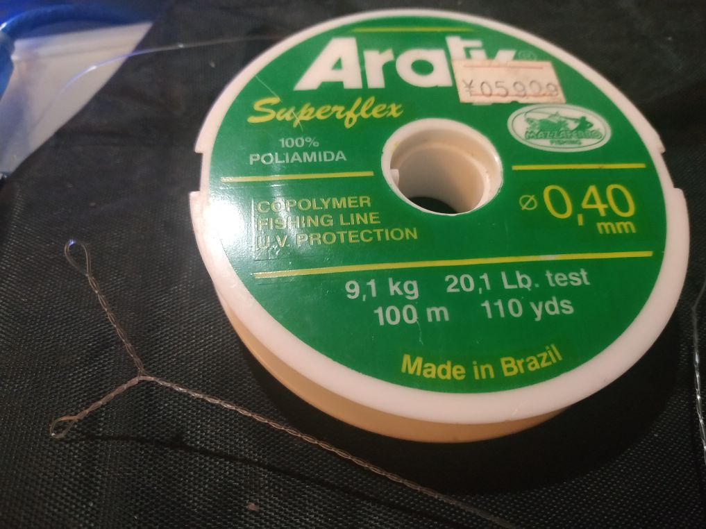
Twisted with a little 3.3 / 5 V motor.
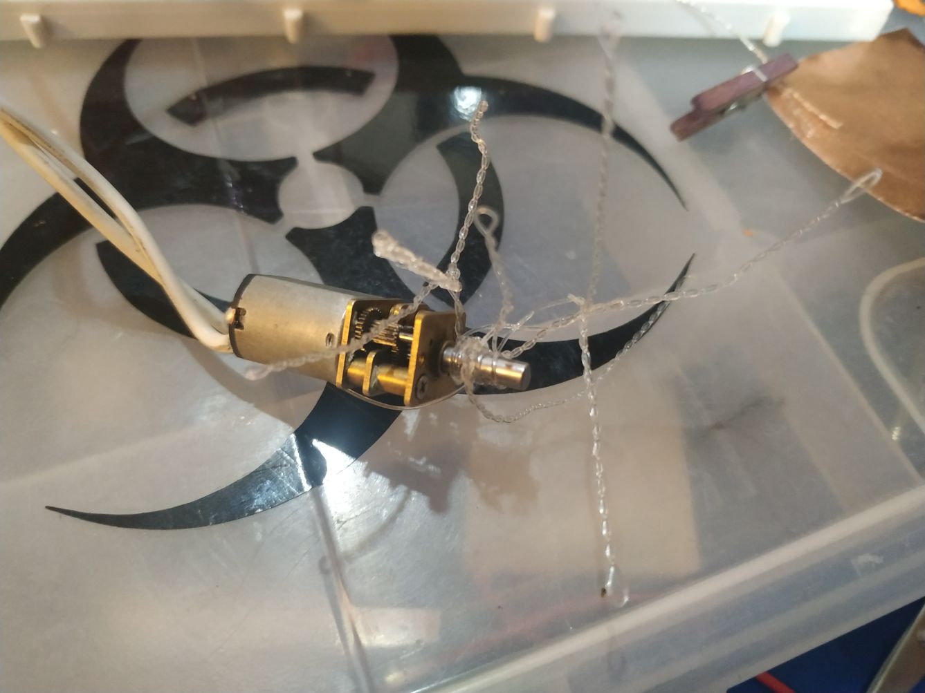
The mess...
The real thing.
This is the configuration we are looking for.
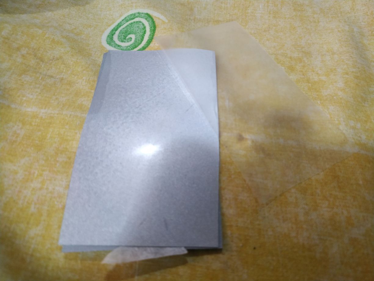
Test with Termoflex
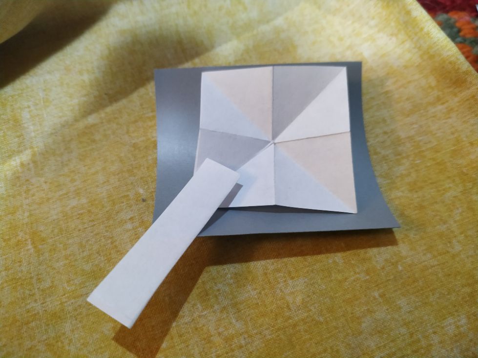
Cut with the material.
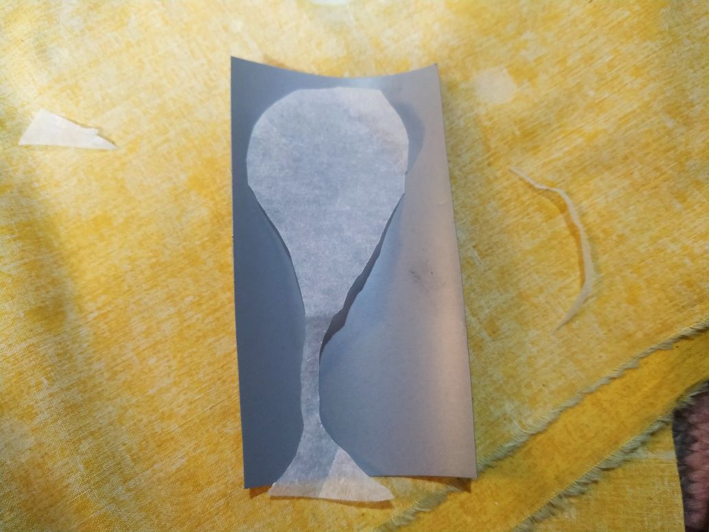
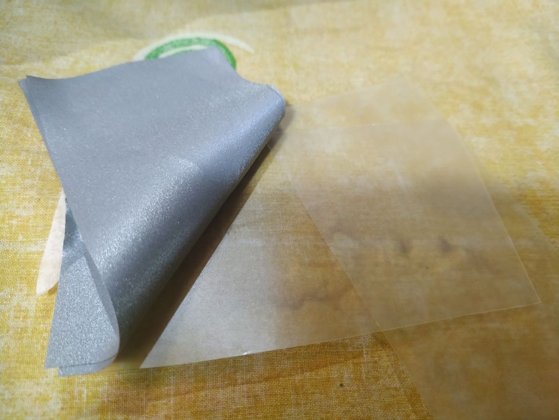
The sandwitch.
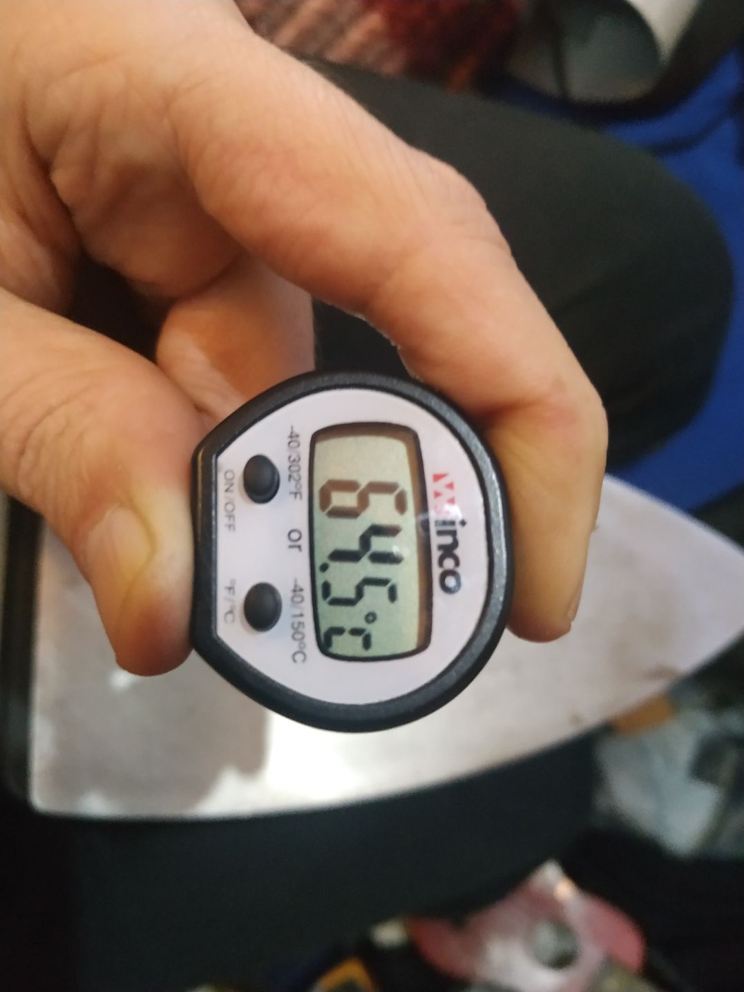
Iron temperature.... around 64 degrees Celcius.
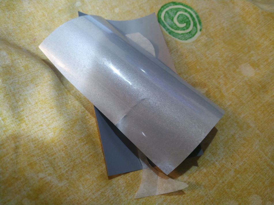
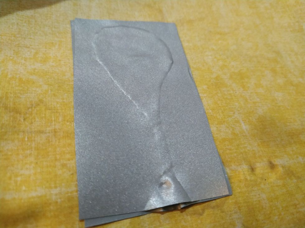
We peel the protective layer.
And then the other side protective layer.
The result.
Another shape.
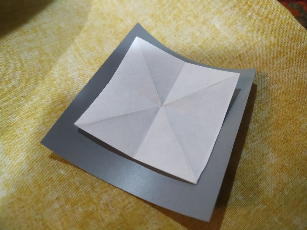
With a channel for the fluid.
A close-up of the pneumatic system.
The system in action.
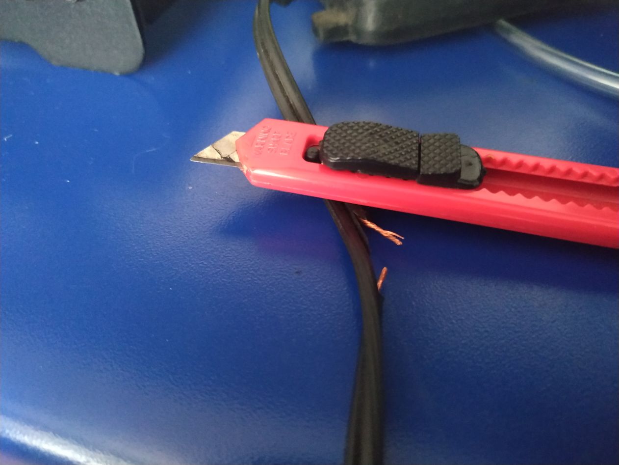
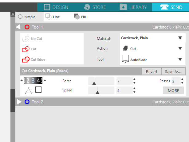
Cutter settings.
...
Final pneumatic device
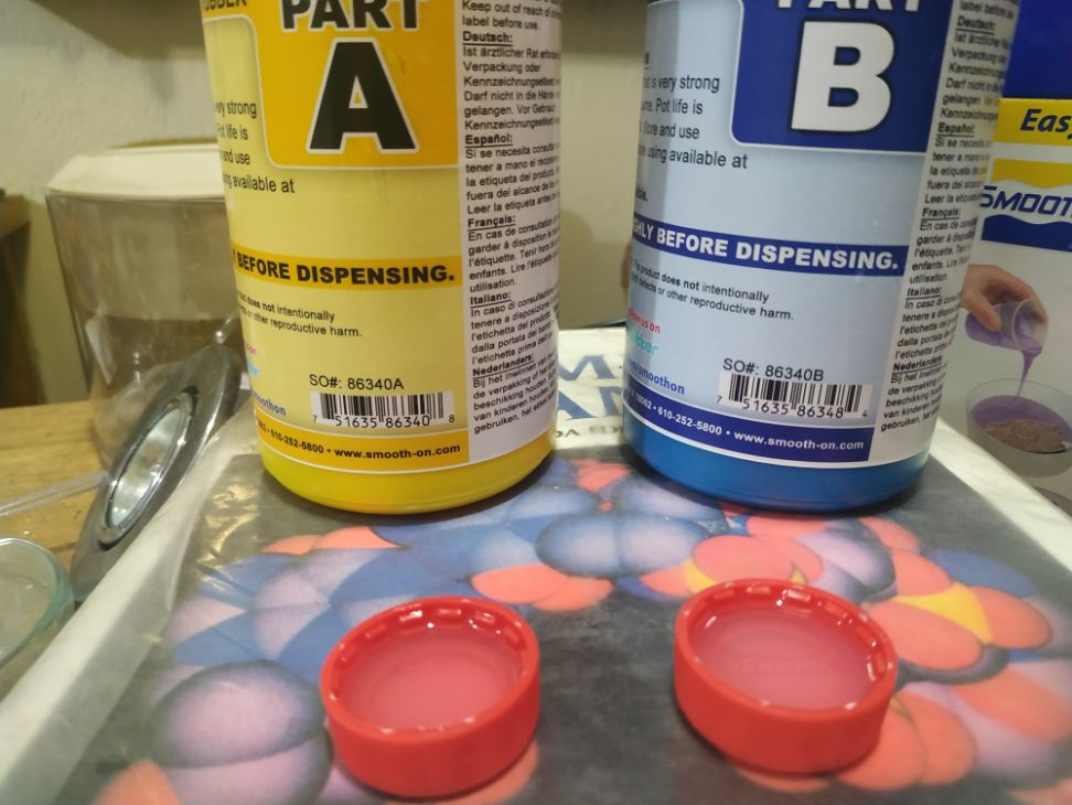
For the fabrication, we used silicone in a PLA mold. The original Stratasis resin printing had a chemical problem, preventing the silicone to cure. We mixed the two components according to the manufacurer instructions.
The three pieces of the mold are assembled and filled with activated silicone. A little bit of modeling clay were used for avoiding spilling.
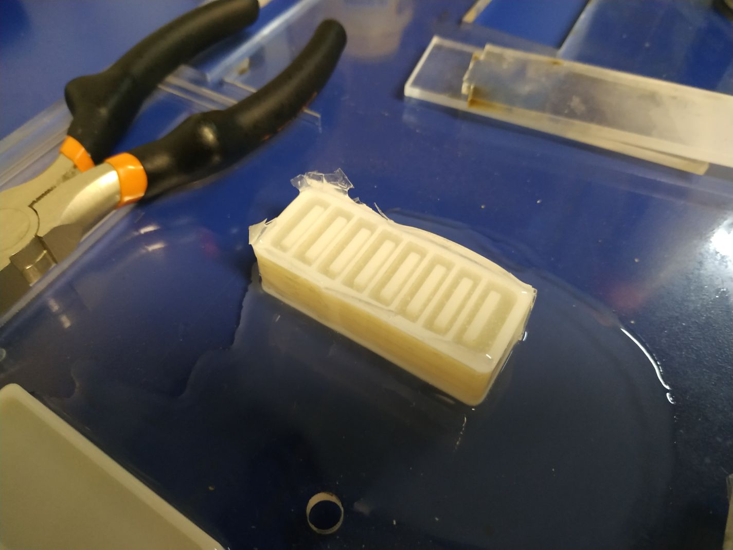
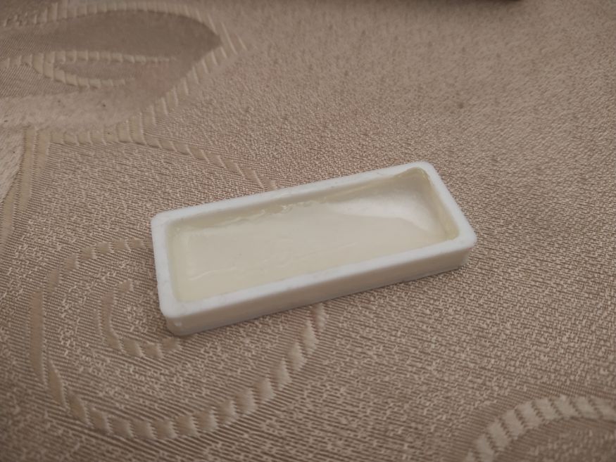
I tested the mold with a little bit of gelatin bioplastic. It worked fine, but the water-based bioplastic tends to deform when dry. In any case, for humid or underwatter applications this material could be tryed.
The adherence to the mold is very low, and the resolution was very high.
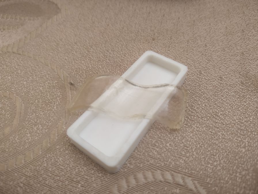
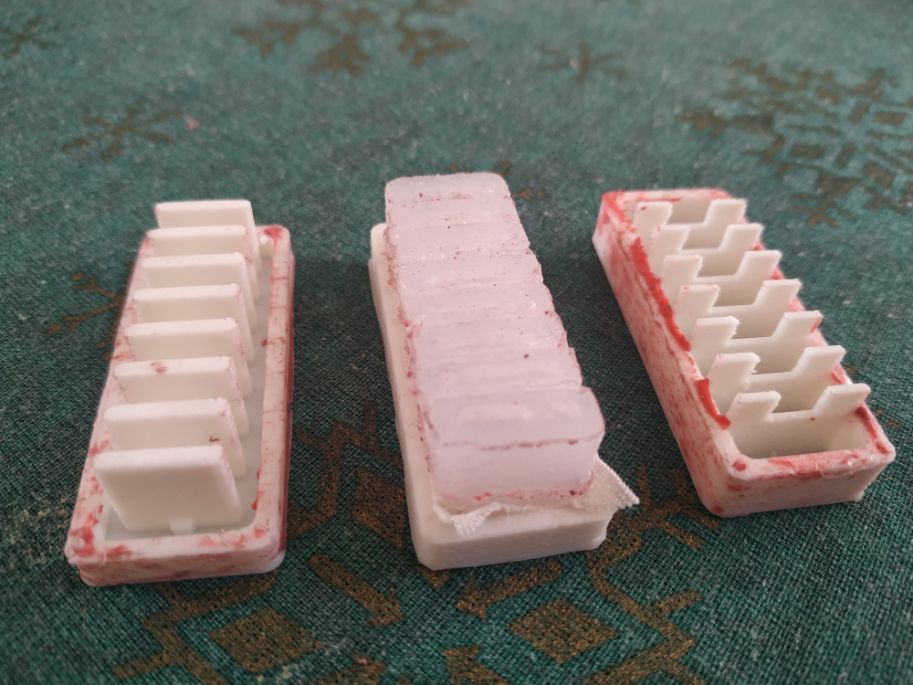
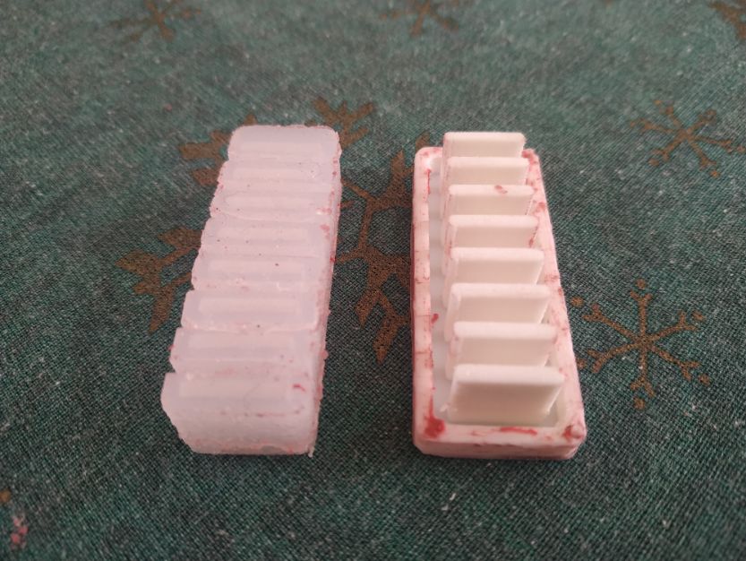
Finally, silicone was used for the final construction. Here we can see the outcast product, with only one piece attached.
We separate the last part very carfully.
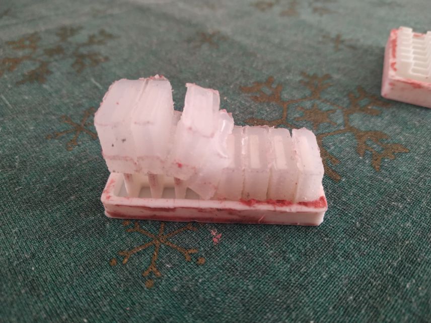
And we get the silicone piece liberated.
The piece is very flexible, and can be closed providing grapping.
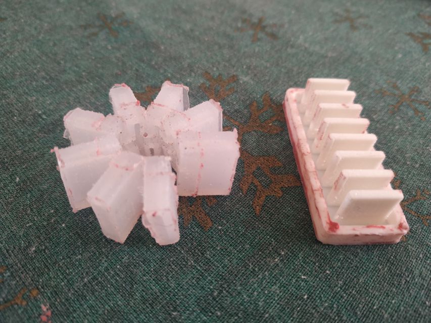
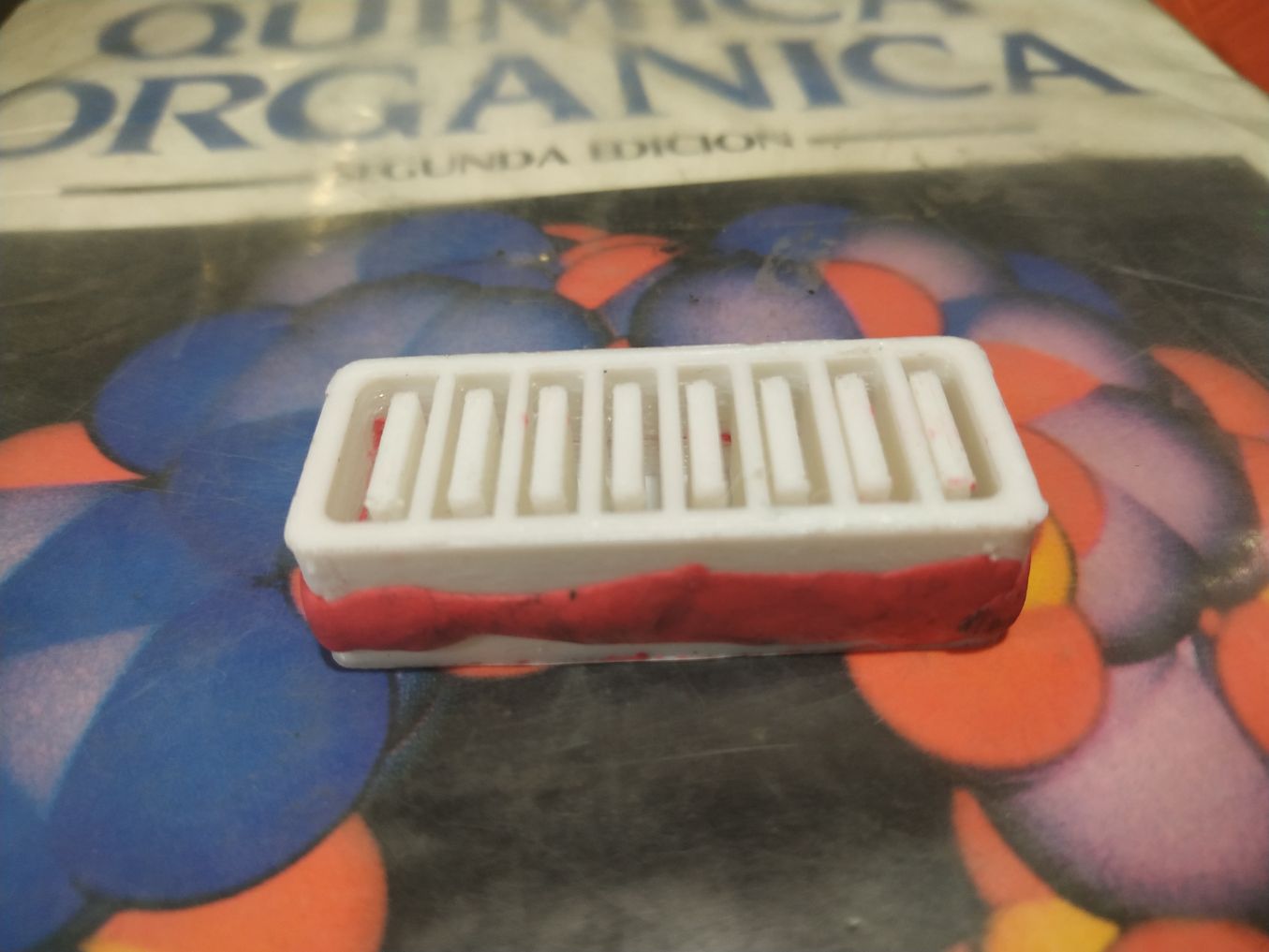
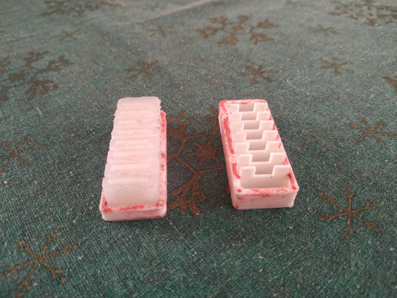
Here we can see the cast compared with the mold. We can see the chambers on the left, and the pins that cast the chambers on the right.
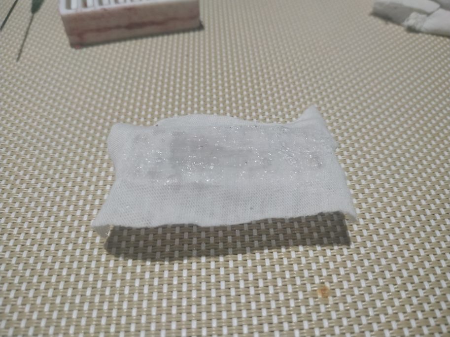
One of the parts of the mold were used to hold the cloth reinforcement in it's place while curing.
The inner part of the construction was designed to mantain it's geometry (the cloth resist stretching). I decided that a little reinforcement with cloth could give the construction a better grip and some resistance.
Here we can see the application of the chemical silicone on the casted silicone. The materials are very compatible.
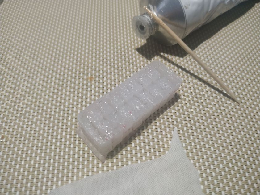
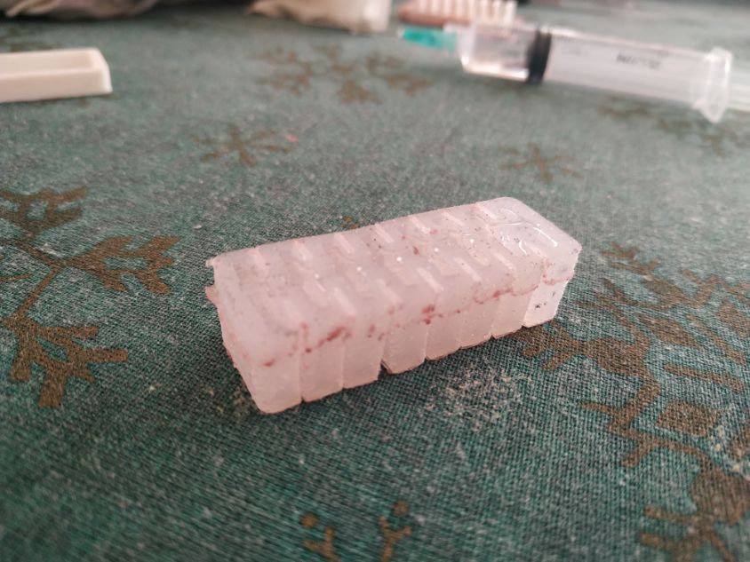
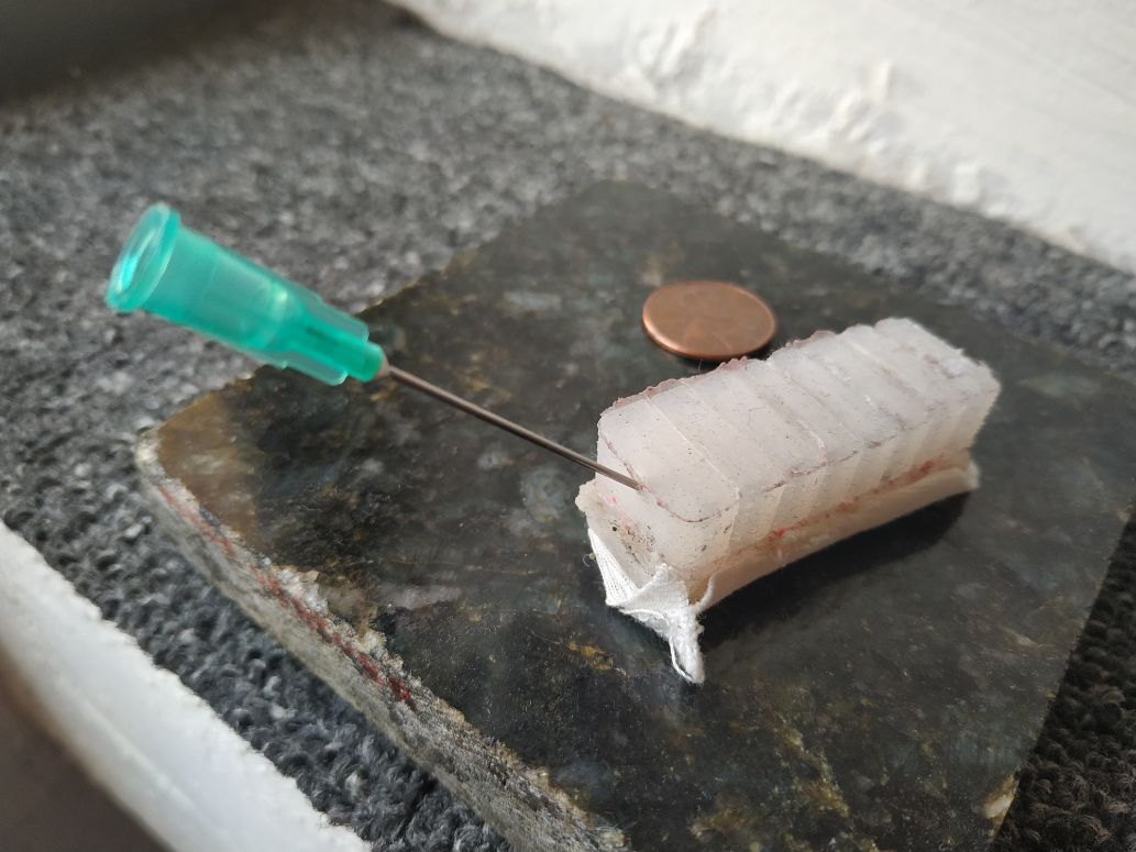
Once the silicone is cured, a piece of non-streachable cloth is attached to one side, keeping it still and providing strength. A sringe needle was then attached. We can see it here with a one cent coin, for scale.
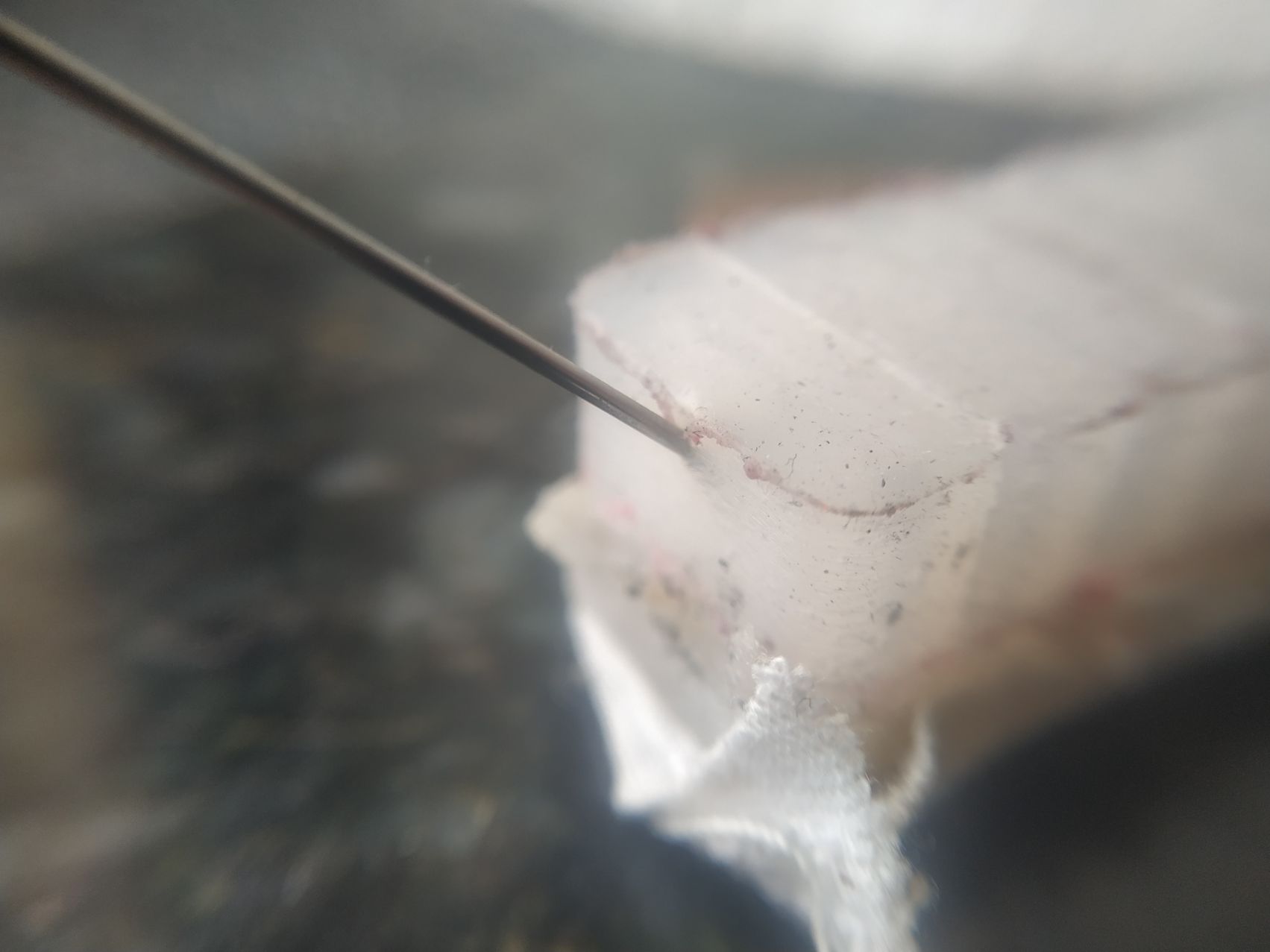
Here we can see the fitting in detail.
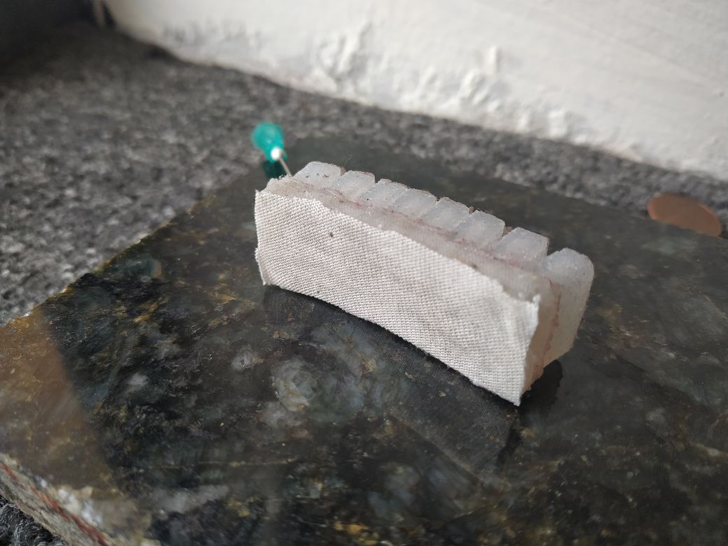
Detail of the bottom of the construction, glued with a silicone/solvent compound (chemical silicone).
In the video we can see the device in action. A pump system can be implemented and can be electronically controlled.
The mold files can be found here in Fusion 360 format or here in Obj format.