5. E-TEXTILES
This week we start to learn about some basics of electronics and programming with Arduino through circuits and sensors (digital and analog) for future Wearables projects. The idea is that we can build our own sensors, program them to interact with an LED and integrate them in a swach.

Some samples of the interaction betwen the fisical touch and eletronics.
Came me to the thought that another thing that reacts through touch (physical or not) and responds to this interaction is love, but we'll talk about that later...
DIGITAL SENSOR - QUICK AND DIRTY
building the Digital Sensor – Quick and Dirty
Digital sensors are binary sensors, so only two states are possible: on/off, 0/1, open/close. As it was my first contact with the world of electronics/programming/sensors, I first wanted to make a simple example as in the tutorial taught in class.
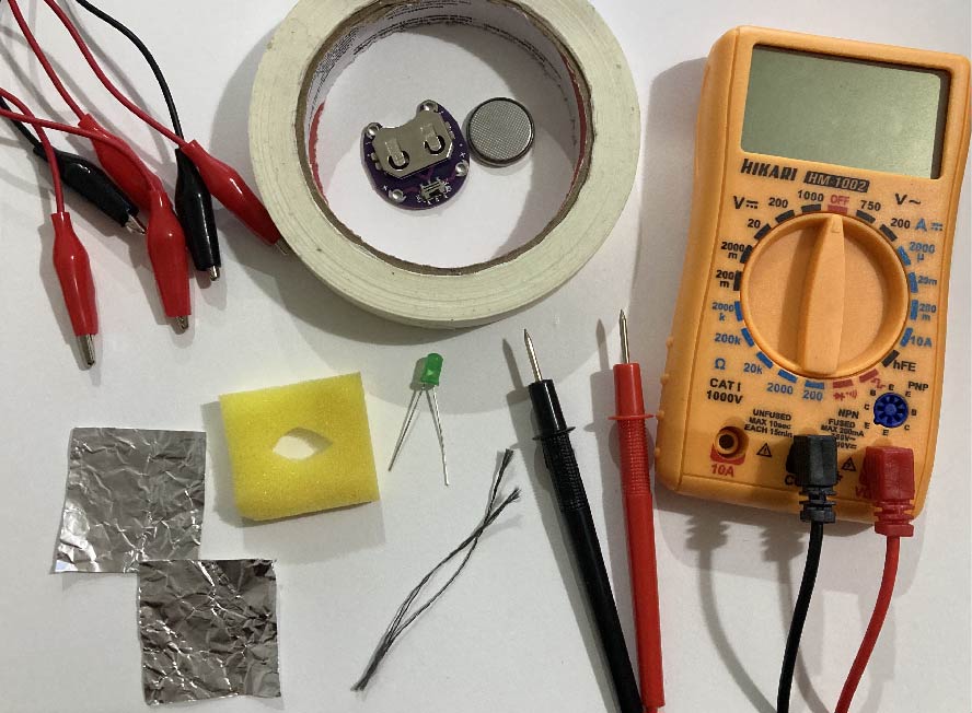
Materials:
- A 4cm x 1cm high sponge square with a hole in the middle;
- Two squares made with 4 cm x 4 cm aluminum foil;
- A little conductive line (2 pieces);
- Scotch tape;
- Alligators;
- 1 LED;
- 3V battery (if using V>3 you will need a resistor / 9V = R>470 Ohm / 5V = R>220Ohm);
- Support for 3V battery;
- Multimiter.
How to
- Build your Digital Sensor with the sponge between the two aluminum sheets, then attach a piece of conductive line to each aluminum sheet with the masking tape;
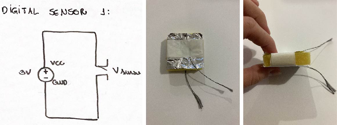
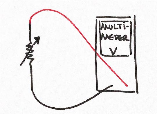
- To find out if the sensor works, we use the Multimeter. Place each end of the multimeter on different pieces of conductive line. Whether the multimeter should beep when you press the sensor and bring its two aluminum faces into contact.
connecting the LED to the Digital Sensor
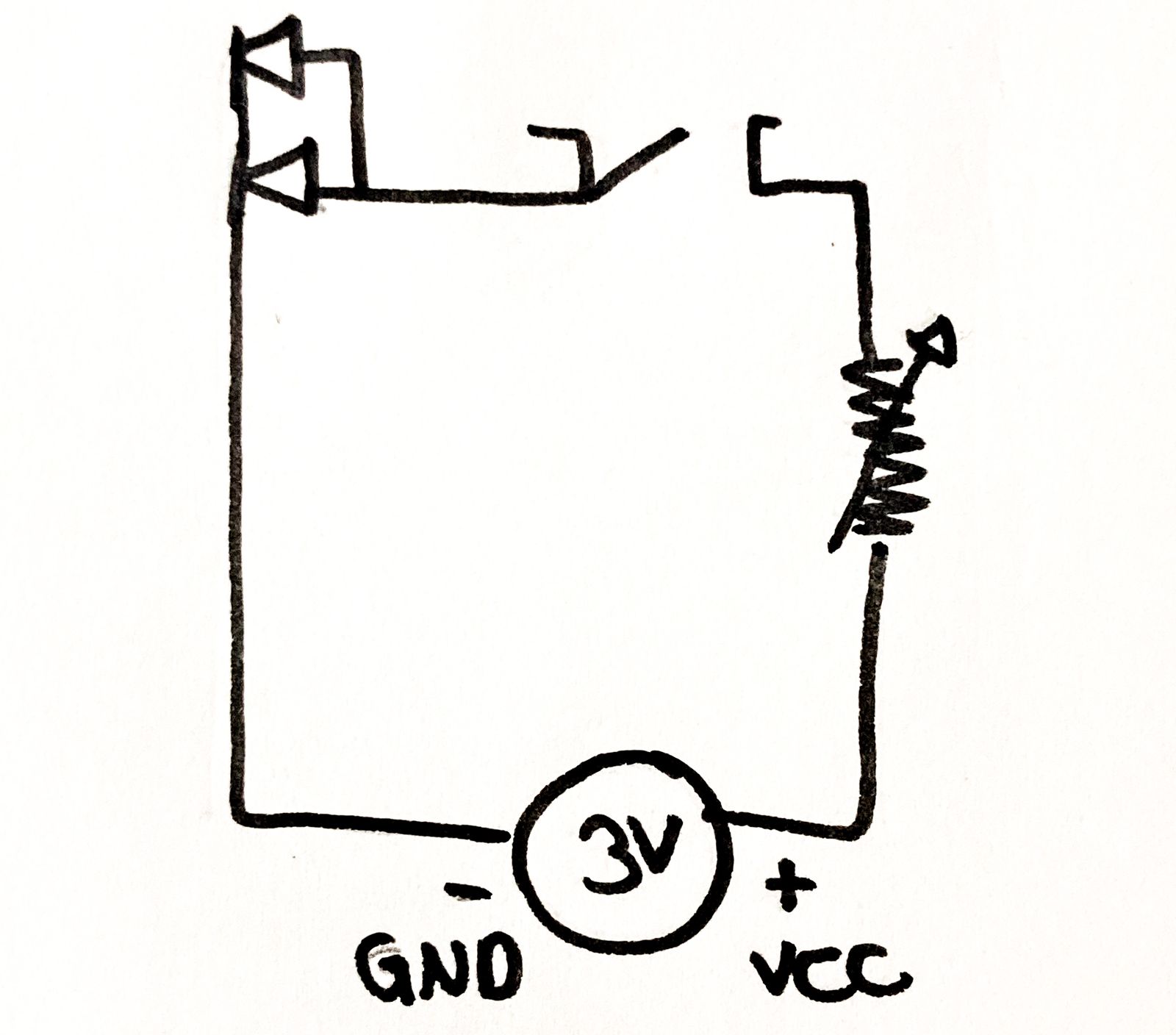
To do this, we make connections like the image below.
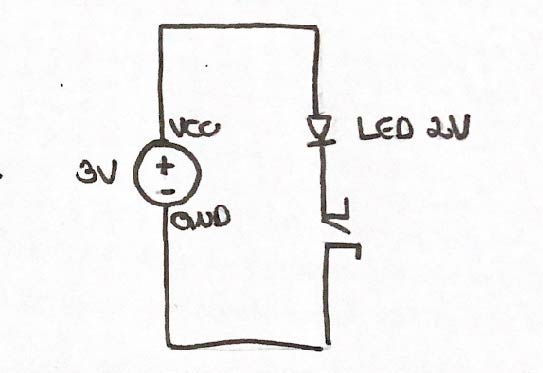
Pay attention to the direction of the LED, because it is a diode, its current runs to only one direction: longer leg + to smaller leg -. So, the alligator connected to the + of the battery, must be the alligator connected to the positive leg of the LED. Once the circuit is done, when pressing the sensor, the LED should light up.
ANALOG SENSOR - KNIT PRESSURE SENSOR
building an Analog Sensor
There are several alternative conductive materials to build an Analog Sensor, from fabrics, threads, dyes/paints and bioplastics (you can find the link for them at the end of this documentation).
As I didn't have access to conductive fabrics in my city and I wanted to combine the idea of handcraft and digital in my project, I chose to work with conductive thread.
Materials:
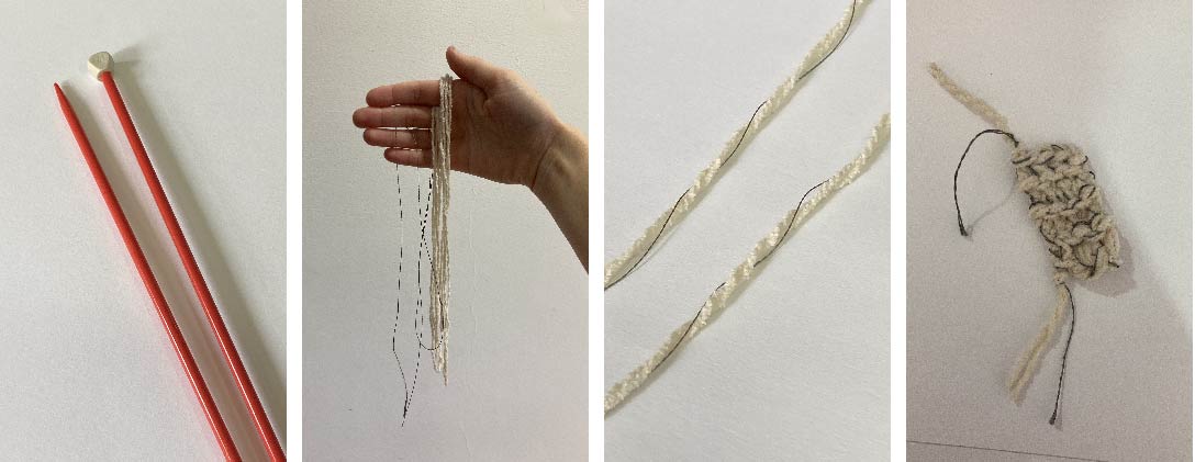
- 2 m of non-conductive line (I used bent);
- 1 m of conductive line;
- Knitting needles;
- Multimeter.
How to
- I made a small swatch, just to test if the sensor would work, using half of the knit stitch (tutorial link at the end of the documentation), it's good to leave some pieces of thread left after finishing so I have room to measure the change of resistance with the multimeter;
- check if the sensor worked, it is only necessary to connect the multimeter to each of the excess thread ends, and press it. If you see the value displayed on your multimeter's digital panel is changing, your Analog Sensor worked. As I recorded the video alone, I connected some alligators to facilitate recording, but it is not recommended to put them because they have their own resistance.
ARDUINO READINGS
We use Arduino to prototyping and reading electronics, sensors, actuators and microcontrollers. For this you will need:
Materials:
- Arduino UNO (in my case I'm using a Brazilian version, Blackboard by Robocore) and USB;
- Breadboard;
- Jumpers;
- Alligators;
- Some LEDS;
- Resistors (I used some 300 Ohms and 10 kOhms);
- Arduino IDE software installed on your computer.
How to
- When connecting the Arduino USB driver (not original) to your computer, it is recommended to check if your card is being recognized by it, as it is possible that installing a duplicate driver will cause malfunction on your computer. To do this, open the Device Manager (if your computer is Windows like mine) and check the ports (COM and LPT), it should look like the image below (for Windows):
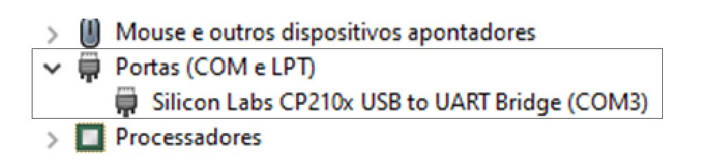
*If it does not appear, you will need to install a driver.
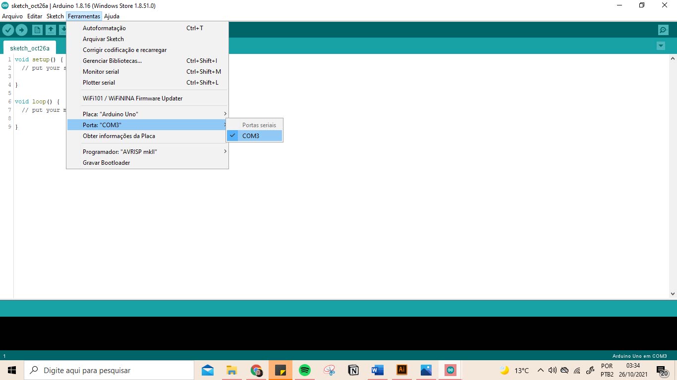
- When opening the software, in tools we select our board (in our case it is Arduino Uno) and the port (in my case it is COM3 port, but this can vary depending on the indication you had by Device Manager).
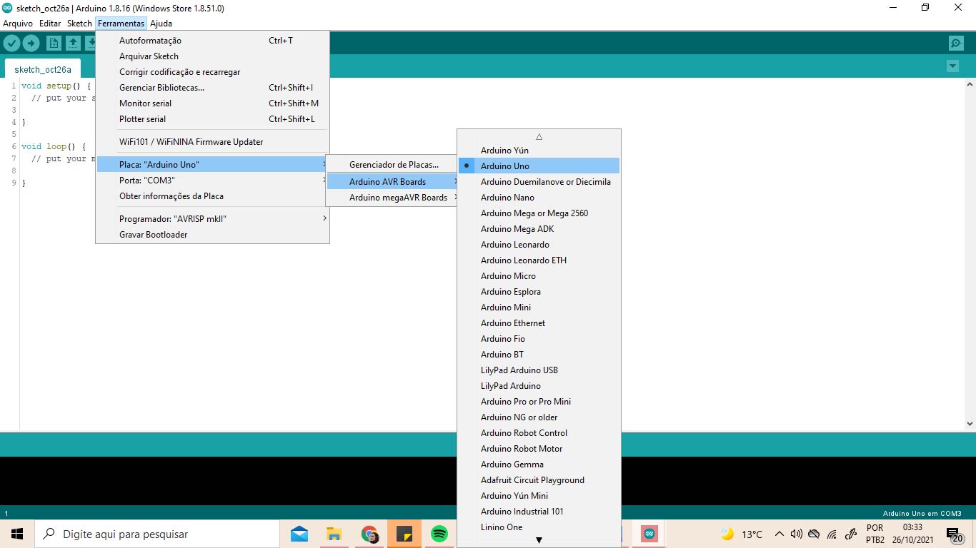
Now your Arduino is ready to use :)
readings on digital sensor
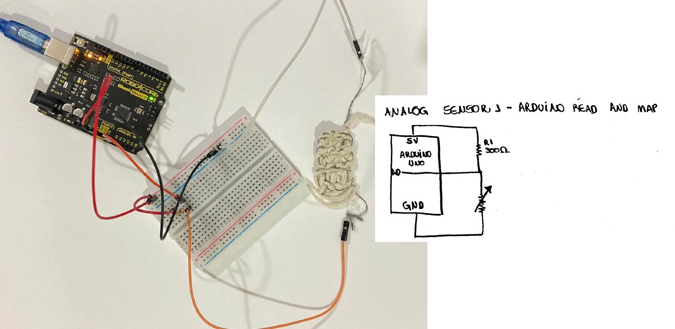
To take the reading, you must first connect the sensor to the breadboard and the breadboard on the Arduino (with the board disconnected from the computer). For that, I made this scheme here:
Combined with this programming in the Software:
/*Emma Pareschi
 * we read the value of a digital sensor connected to pin digital_sensor_pin and
 * we print it on the Serial Monitor
 */

int digital_sensor_pin = 8;     //change the pin, where the sensor is connected?
int digital_sensor_value = 0;

void setup() {
  // put your setup code here, to run once:
  pinMode(digital_sensor_pin, INPUT); //define the pin as INPUT
  Serial.begin(9600);

}

void loop() {
  // put your main code here, to run repeatedly:
  digital_sensor_value = digitalRead(digital_sensor_pin); // read the sensor

  Serial.println(digital_sensor_value); //print the value
  delay(100);

}
It is important to check if the sketch pins match the pins that are connected to the Arduino board.

Then just check if the writing is correct, on the arrow indicated in the upper left corner of the page. If no error message appears, just load the programming onto the board using the arrow on the side.
To view the reading, open the serial monitor (tools > Serial monitor or Ctrl + Shift + M). When pressing the button with the serial monitor open, you will see that the indicated numbers have changed from 1 to 0 and 0 to 1.
readinGs on analog sensor
For this reading it is necessary to disconnect the computer board and make the new connections.
With the connections made, just open the smoothing option (File > Examples > 03.Analog > Smoothing).
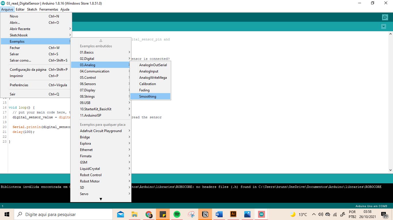
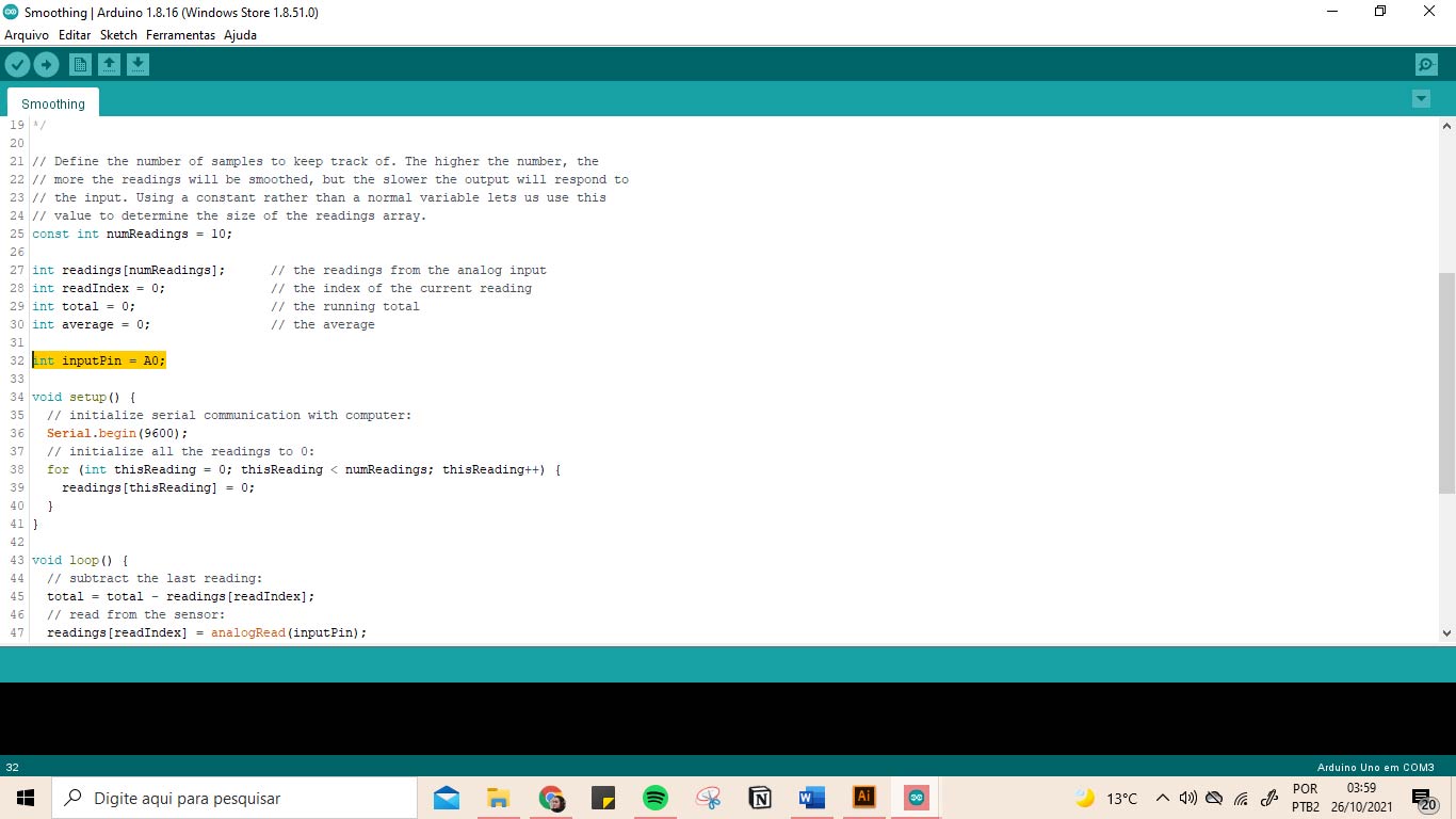
Always check that the pins indicated in the finished sketches match the pins you have connected to your breadboard. *Another note: analog sensors use the ANALOG IN row, or D3; D5; D6; D9; D10; D11 of the arduino.
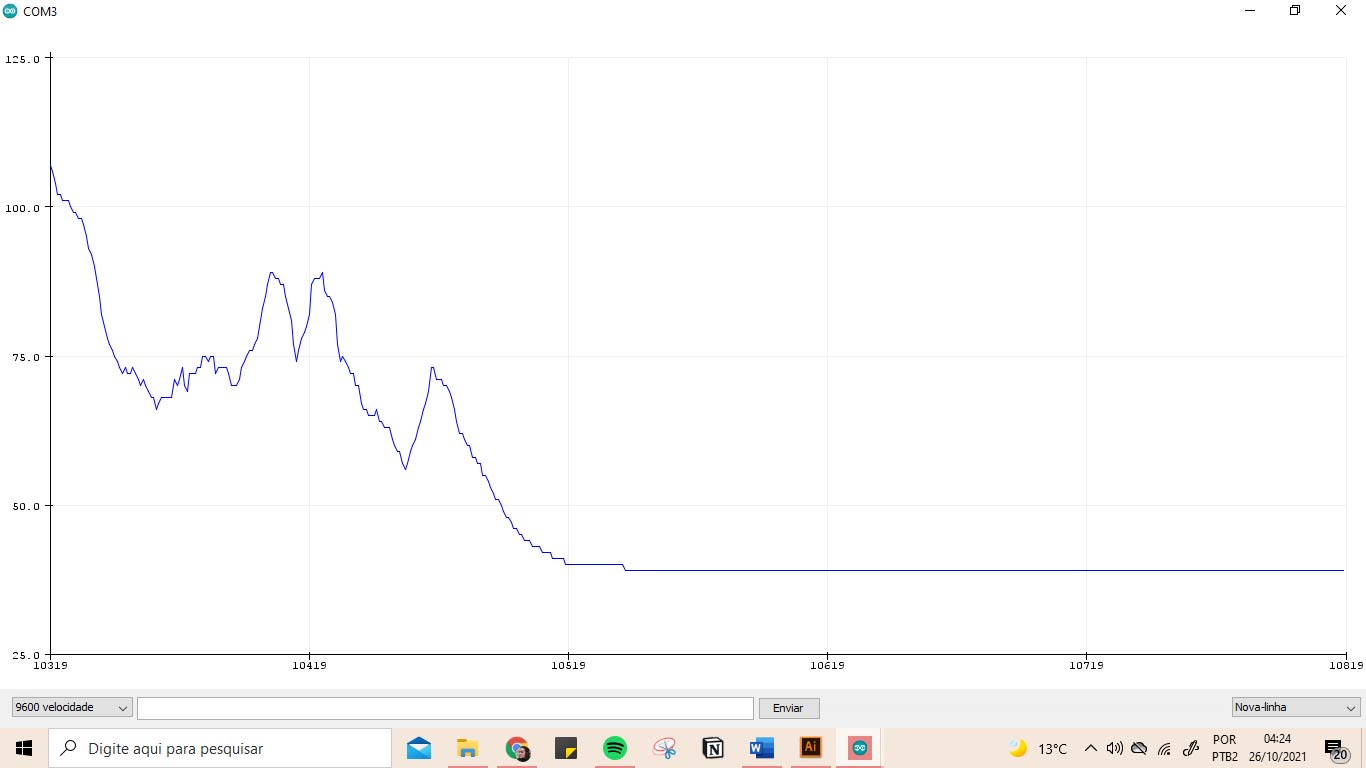
To read it, just open the Serial Plotter (tool> Serial Plotter or Ctrl+Shift_L). You should see the displayed values decreasing when tapping your Analog Sensor. Write these values down for future schedules with him. In my case the variation was from 15 to 45.
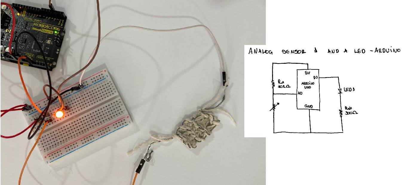
connecting analog sensor and a LED
To check the sensor operation along with the programming, we connect an LED to the circuit. For that, I used this scheme:
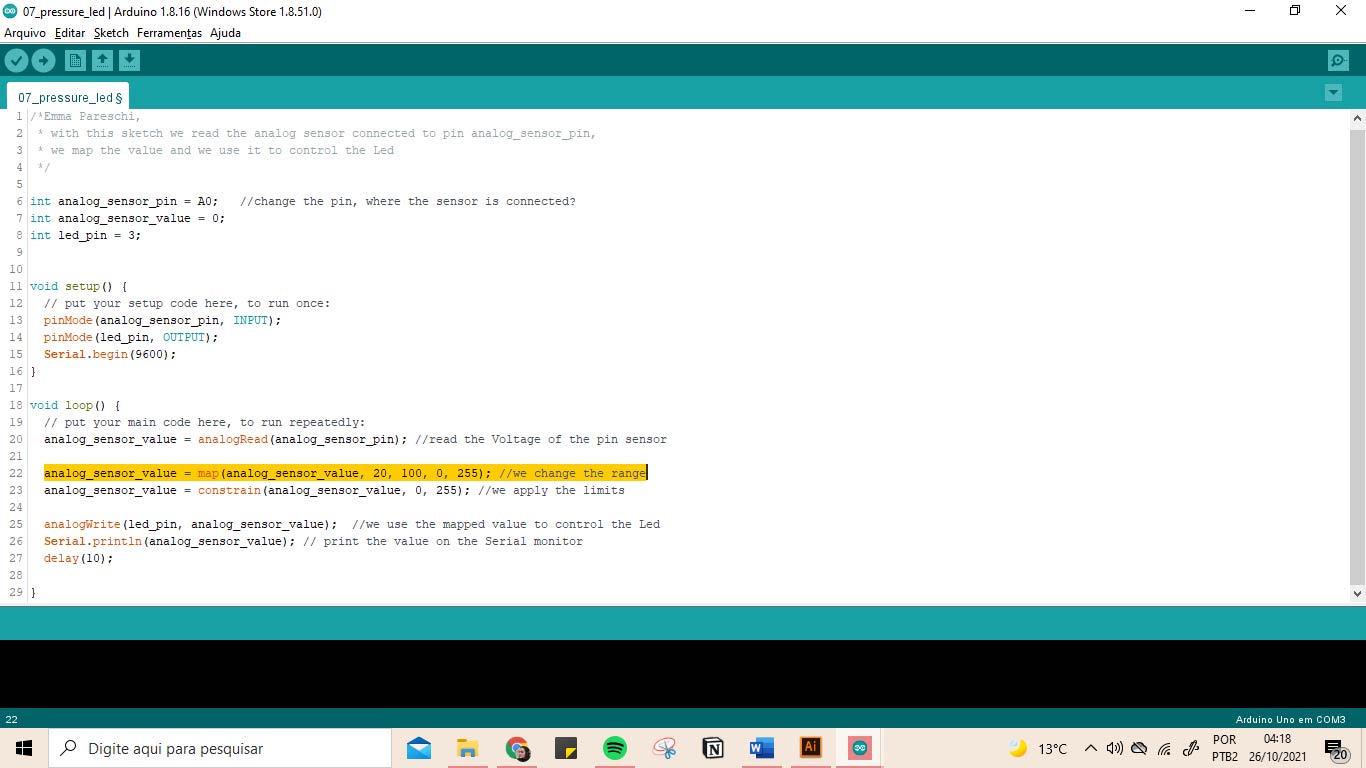
And this sketch:
/*Emma Pareschi,
 * with this sketch we read the analog sensor connected to pin analog_sensor_pin,
 * we map the value and we use it to control the Led
 */

int analog_sensor_pin = A0;   //change the pin, where the sensor is connected?
int analog_sensor_value = 0;
int led_pin = 3;


void setup() {
  // put your setup code here, to run once:
  pinMode(analog_sensor_pin, INPUT);
  pinMode(led_pin, OUTPUT);
  Serial.begin(9600);
}

void loop() {
  // put your main code here, to run repeatedly:
  analog_sensor_value = analogRead(analog_sensor_pin); //read the Voltage of the pin sensor

  analog_sensor_value = map(analog_sensor_value, 42, 85, 0, 255); //we change the range
  analog_sensor_value = constrain(analog_sensor_value, 0, 255); //we apply the limits

  analogWrite(led_pin, analog_sensor_value);  //we use the mapped value to control the Led
  Serial.println(analog_sensor_value); // print the value on the Serial monitor
  delay(10);

}

In the line indicated in yellow, you can see that the numbers 15 and 45 have been placed, that is, the result of my previous measurements.
However, when uploading this programming to my board, I noticed that when I pressed my sensor, the dimming of my LED was almost imperceptible. I suspected it was because of the size, where a meter of line had only 50 Ohms (with variations due to the plot and the touch).
second try: knit pressure analog sensor
This led me to make a second Knit Pressure Sensor, with a bigger size. For these I used:
• 6m of non-conductive line (bent once) • 3m of conductive line; • Knitting needles.
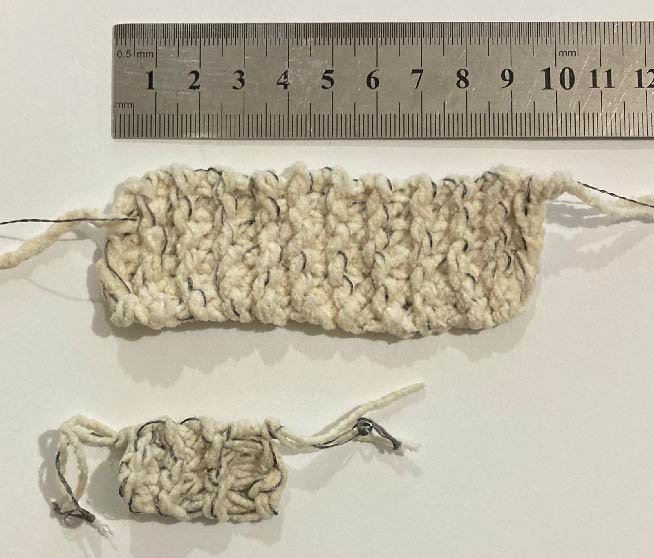
When testing its variation against the smoothing parameters, I saw better results, with variations ranging from 20 to 100.
Connecting Againd Analog Sensor and a LED
To check the sensor operation along with the programming, we connect an LED to the circuit. For this, I used the same scheme and previous programming, I just changed the breadboard sensor and the variation of the numbers in the programming (yellow underscore).
When loading and checking the operation of my sensor with the LED, I saw that it was happening like the previous show, with almost imperceptible variations in the light intensity. But, when testing with the sensor folded, the circuit worked perfectly.
A LITTLE HEART: final sample
It came to my mind, while studying touch sensors, that something that responds to touch (physical or emotional) is love! Therefore, in order to integrate a digital and an analog sensor in a project, I decided to make an embroidery in which when touching the wound of the heart (band-aid), the led suffers a change in the resistance of the circuit and "cries" ( led blinks). At the same time, if we wipe the tears from the heart (swich on/off done with beads), it stops crying!
very inspired by Domenique's work
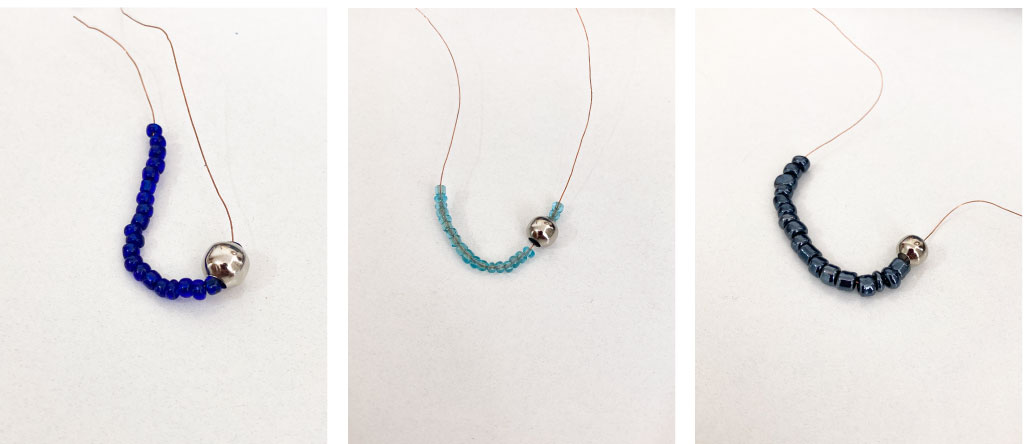
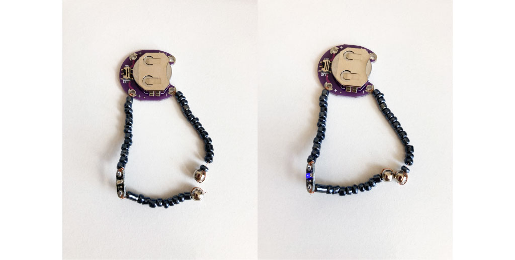
beads digital sensor
To make my digital sensor I used very fine copper wire, attached to a sewable 3v battery holder, with a metal bead at the end (when metal beads are separated - open is off, when closed it is on). I played around a little with the choice of colors to make the tears in the heart.
Testing my digital swich from Brunna Ramos on Vimeo.
analog sensor
For the band-aid part, I used the knitted sensor I had made earlier. I just folded it in half when attaching it to the fabric and did some embroidery details to make it look like a band-aid!
led tears

To make this embroidery I used leftover interior design fabric swatches!
To make the tears, I first decided to connect them in series with sewable LEDs.
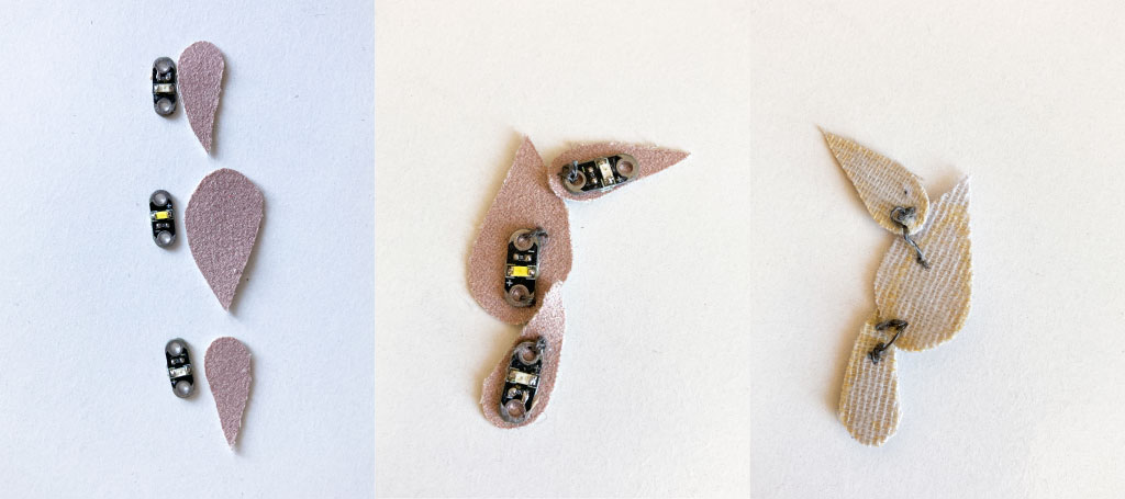
However, it didn't shine as I wanted and I realized that to use a 3V battery, the circuit must be connected in parallel.
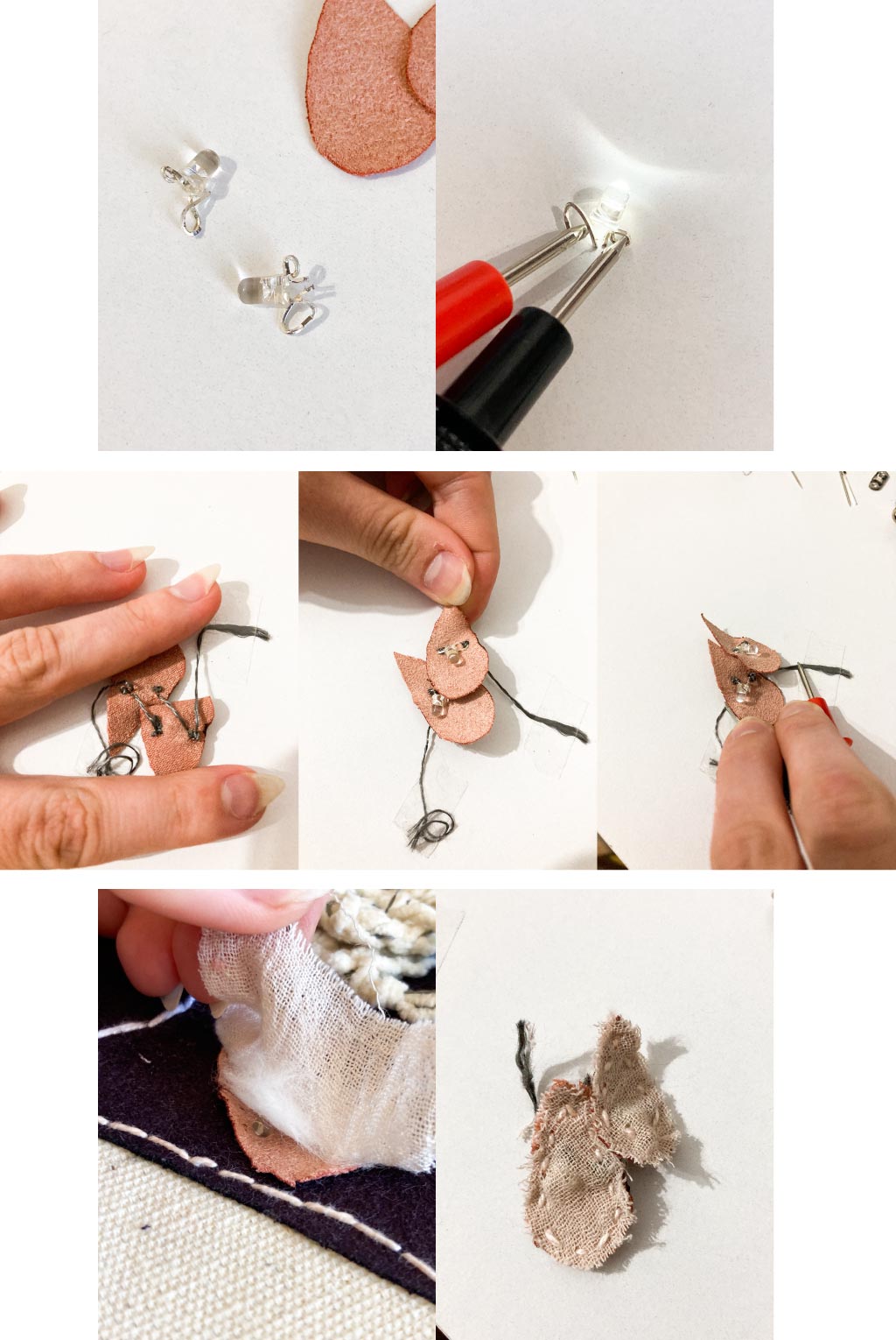
So, I took two smaller LEDs that I had and bent their legs with the help of pliers so that they could be sewn together. Then, I connected them in parallel in two teardrop molds on the fabric with conductive thread.
For the final embroidery, I also put a cotton over the LEDs to give an effect and a fabric to hide it.
final result
With the tears ready, I finished the final embroidery connecting the two sensors.

I almost didn't record my embroidery working with both sensors, luckily, a friend recorded it while I showed it to another! (you can see my happiness to see it work hahah)
REFERENCES
projects
Re-FREAM Embroidered Touch / Life Space
Crochet/ Knit pressure sensors
Sonic Patchwork by Rylie Sweem