13. SKIN ELETRONICS
This week talks about a new approach in the beauty and medicine industry... makeup, bandages and electronic applications that can be integrated into the skin, making the human-device interaction.
INSPIRATIONS
I confess that when I attended Katia Vega's class I had two impressions: the first, my God! I can't believe I'm having a class with this woman... the second one reminded me of the customs of Brazilian carnival, a traditional period of the year where samba school parades take place and everyone dresses up to accompany and celebrate!

So, for this affectionate memory of Carnival, I wanted to do something relating to electronic makeup.
Beauty Wearable Devices are defined as cosmetic computing, a concept that expands the vocabulary of onskin wearable devices. (PARK, 2020, p. 13)
Researching the subject a little deeper, I found this article by Eun-Young Park that shows several examples on the subject (it shows many works by Katia herself too!). In it, two projects involving false eyelashes and LEDs caught my attention: LED eyelashes by Soomi Park and Digital Eyeshadow by Lulin Ding.

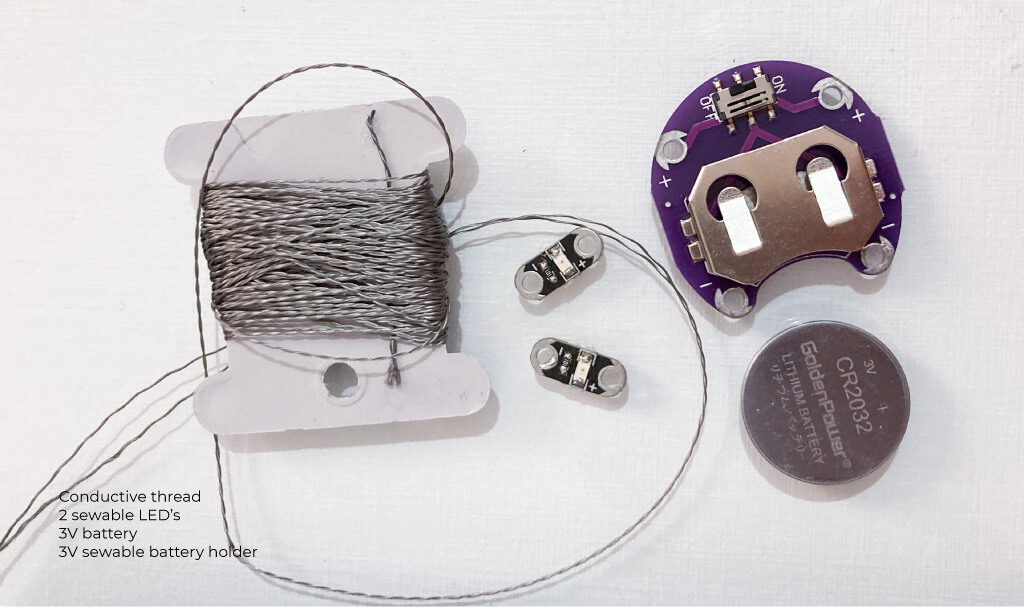
Some materials for working with skin electronics according to Park (2020) and Katia Vega:
- Conductive inks;
- RFID tags;
- small magnets;
- conductive ink nail polish;
- conductive artificial hair; ...
MY IDEIA
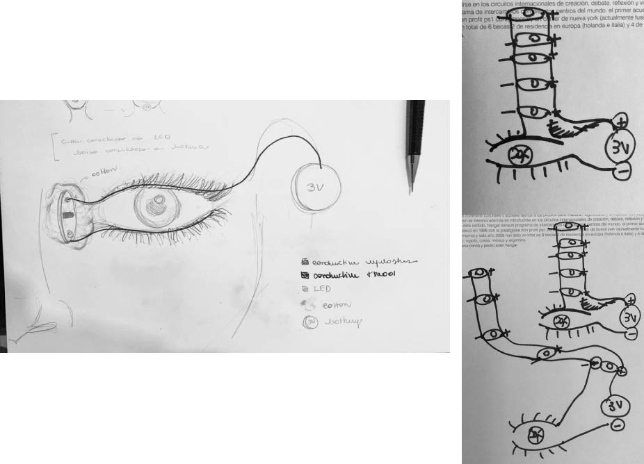
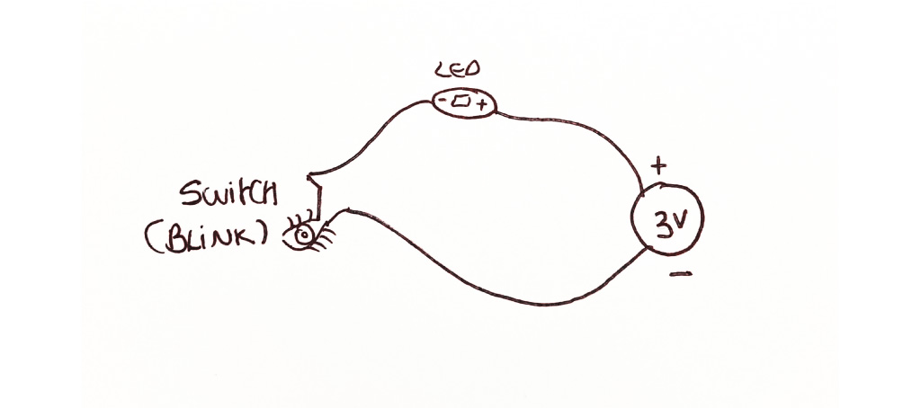
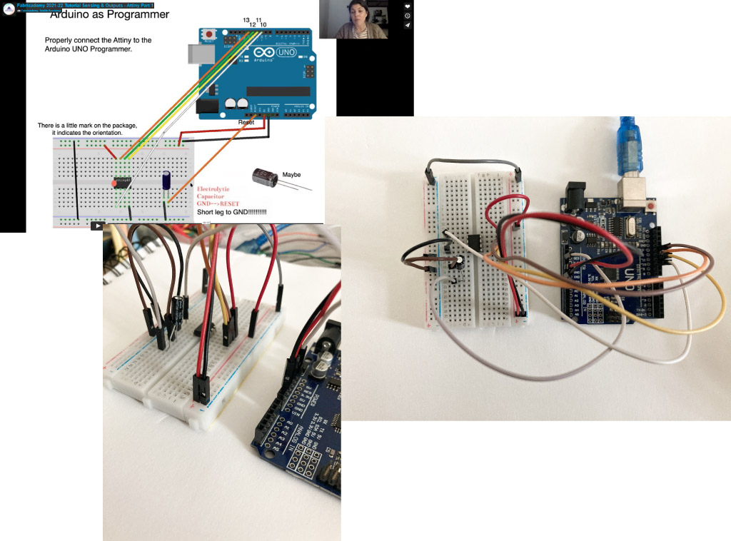
So, my idea is to make a makeup where, when blinking using false eyelashes painted with conductive dye, an LED lights up in the inner corner of the eye (since we have the habit of using highlighter and glitter to illuminate this area).
Angela and I debated a bit about the possibilities of this idea, what would work or not when setting up the circuit. The conclusion we came to is: the image on the left would not work, it would be better to follow the circuit of the images on the right...
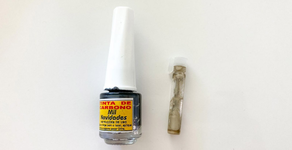
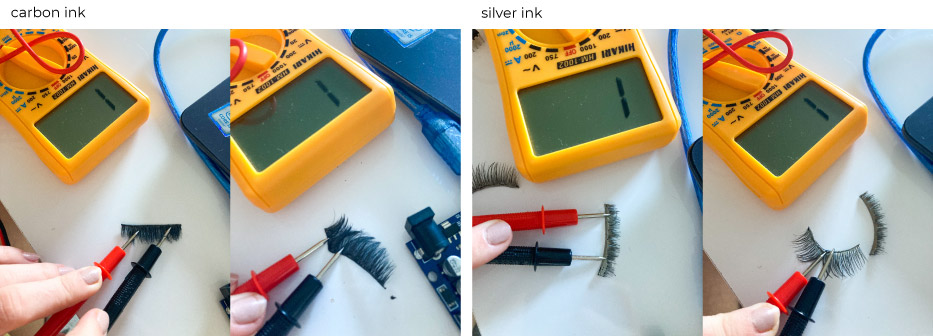
1st try - painting my eyelashes
To make my false eyelashes conductive I tested two inks: a carbon ink and a silver ink. Unfortunately, neither of them worked.
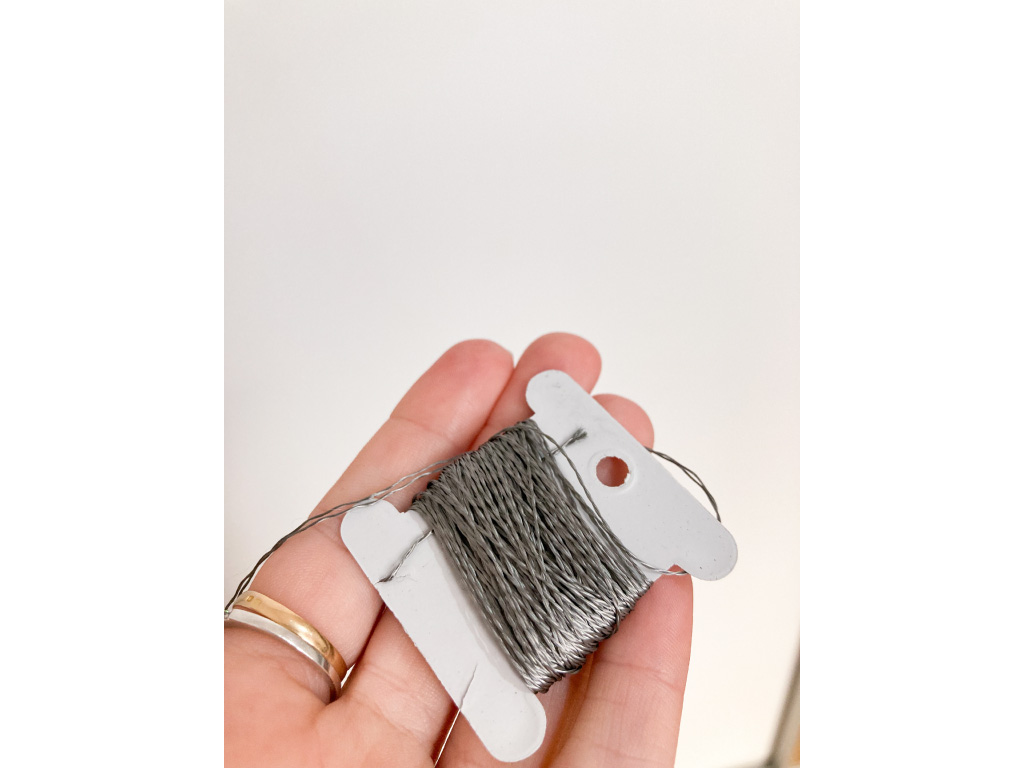
2nd try - using conductive thread
As my conductive inks didn't made my false eyelashes conductive, I decide to use an "quick and dirty" solution: made an eyeliner with conductive thred (with helped me a lot during the hole eletronic process during fabricademy!).
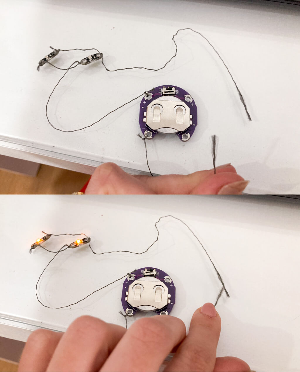
I made an simple circuit using 2 leds, 1 sewable battery holder, conductive thread and 1 3V battery.
First, I decided to test out of my face, simulating the blink:
Then, to glue the circuit on my face I use this black eyelashes glue.

The circuit made was quite simple: the battery was hidden behind my ear and the LEDs were connected in parallel with the battery, two lines were loose to make the switch (one was stuck above and the other below the eye) and light up the LED when I blink. First I had made the circuit with two LEDs, but it was very difficult to stick them both to my face and make the blink work so I ended up working with just one.

But... it was not so easy to glue the thread on my face! In my first tests it was working (I had to blink very hard), but when I finished but makeup, the LED was lighting without the blinkins, and was turning off when I blinked (doing the opposite of waht I intended). I suppose that when finishing the makeup with the eyeliner, the lines were stuck together and the circuit was closed (I couldn't see very well since everything was black!), and with the blink the circuit became unstable, the lines came away from each other and turned off the led. I decide to accept this way.
Final circuit:
Some videos: e-make up working!
ATTINY 85
Arduino as ISP
Attiny is a microcontroller, and due to its size (approximately 1cm), it is ideal for making electronic circuits on skin or clothing, for example, as in the case of this week's assignment.
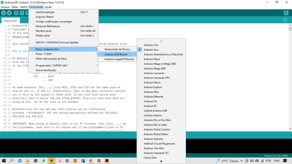
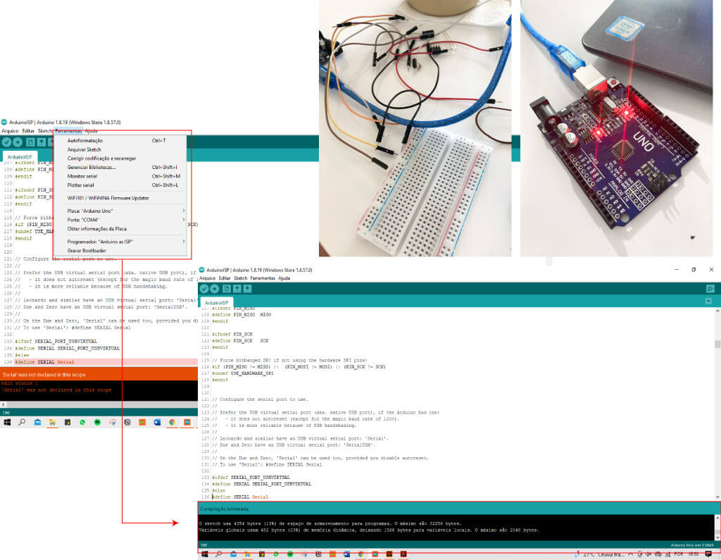
For this, we use Arduino as a programmer. And we prepare our board in the arduino IDE, using the sketch examples > ArduinoISP > ArduinoISP with the board empty, just connected to the computer.
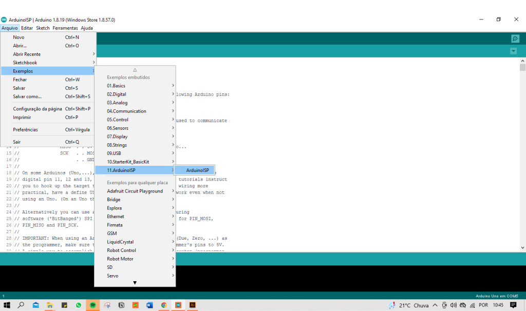
It is necessary to check in tools the board (in my case, arduino uno), and the port, (in my case COM5), and the programmer (for this we select Arduino as ISP).
code:
// ArduinoISP
// Copyright (c) 2008-2011 Randall Bohn
// If you require a license, see
// https://opensource.org/licenses/bsd-license.php
//
// This sketch turns the Arduino into a AVRISP using the following Arduino pins:
//
// Pin 10 is used to reset the target microcontroller.
//
// By default, the hardware SPI pins MISO, MOSI and SCK are used to communicate
// with the target. On all Arduinos, these pins can be found
// on the ICSP/SPI header:
//
//               MISO °. . 5V (!) Avoid this pin on Due, Zero...
//               SCK   . . MOSI
//                     . . GND
//
// On some Arduinos (Uno,...), pins MOSI, MISO and SCK are the same pins as
// digital pin 11, 12 and 13, respectively. That is why many tutorials instruct
// you to hook up the target to these pins. If you find this wiring more
// practical, have a define USE_OLD_STYLE_WIRING. This will work even when not
// using an Uno. (On an Uno this is not needed).
//
// Alternatively you can use any other digital pin by configuring
// software ('BitBanged') SPI and having appropriate defines for PIN_MOSI,
// PIN_MISO and PIN_SCK.
//
// IMPORTANT: When using an Arduino that is not 5V tolerant (Due, Zero, ...) as
// the programmer, make sure to not expose any of the programmer's pins to 5V.
// A simple way to accomplish this is to power the complete system (programmer
// and target) at 3V3.
//
// Put an LED (with resistor) on the following pins:
// 9: Heartbeat   - shows the programmer is running
// 8: Error       - Lights up if something goes wrong (use red if that makes sense)
// 7: Programming - In communication with the slave
//

#include "Arduino.h"
#undef SERIAL


#define PROG_FLICKER true

// Configure SPI clock (in Hz).
// E.g. for an ATtiny @ 128 kHz: the datasheet states that both the high and low
// SPI clock pulse must be > 2 CPU cycles, so take 3 cycles i.e. divide target
// f_cpu by 6:
//     #define SPI_CLOCK            (128000/6)
//
// A clock slow enough for an ATtiny85 @ 1 MHz, is a reasonable default:

#define SPI_CLOCK       (1000000/6)


// Select hardware or software SPI, depending on SPI clock.
// Currently only for AVR, for other architectures (Due, Zero,...), hardware SPI
// is probably too fast anyway.

#if defined(ARDUINO_ARCH_AVR)

  #if SPI_CLOCK > (F_CPU / 128)
    #define USE_HARDWARE_SPI
  #endif

#endif

// Configure which pins to use:

// The standard pin configuration.
#ifndef ARDUINO_HOODLOADER2

  #define RESET     10 // Use pin 10 to reset the target rather than SS
  #define LED_HB    9
  #define LED_ERR   8
  #define LED_PMODE 7

  // Uncomment following line to use the old Uno style wiring
  // (using pin 11, 12 and 13 instead of the SPI header) on Leonardo, Due...

  // #define USE_OLD_STYLE_WIRING

  #ifdef USE_OLD_STYLE_WIRING

    #define PIN_MOSI    11
    #define PIN_MISO    12
    #define PIN_SCK     13

  #endif

  // HOODLOADER2 means running sketches on the ATmega16U2 serial converter chips
  // on Uno or Mega boards. We must use pins that are broken out:
#else

  #define RESET         4
  #define LED_HB        7
  #define LED_ERR       6
  #define LED_PMODE     5

#endif

// By default, use hardware SPI pins:
#ifndef PIN_MOSI
  #define PIN_MOSI  MOSI
#endif

#ifndef PIN_MISO
  #define PIN_MISO  MISO
#endif

#ifndef PIN_SCK
  #define PIN_SCK   SCK
#endif

// Force bitbanged SPI if not using the hardware SPI pins:
#if (PIN_MISO != MISO) ||  (PIN_MOSI != MOSI) || (PIN_SCK != SCK)
  #undef USE_HARDWARE_SPI
#endif


// Configure the serial port to use.
//
// Prefer the USB virtual serial port (aka. native USB port), if the Arduino has one:
//   - it does not autoreset (except for the magic baud rate of 1200).
//   - it is more reliable because of USB handshaking.
//
// Leonardo and similar have an USB virtual serial port: 'Serial'.
// Due and Zero have an USB virtual serial port: 'SerialUSB'.
//
// On the Due and Zero, 'Serial' can be used too, provided you disable autoreset.
// To use 'Serial': #define SERIAL Serial

#ifdef SERIAL_PORT_USBVIRTUAL
  #define SERIAL SERIAL_PORT_USBVIRTUAL
#else
  #define SERIAL Serial
#endif


// Configure the baud rate:

#define BAUDRATE    19200
// #define BAUDRATE 115200
// #define BAUDRATE 1000000


#define HWVER 2
#define SWMAJ 1
#define SWMIN 18

// STK Definitions
#define STK_OK      0x10
#define STK_FAILED  0x11
#define STK_UNKNOWN 0x12
#define STK_INSYNC  0x14
#define STK_NOSYNC  0x15
#define CRC_EOP     0x20 //ok it is a space...

void pulse(int pin, int times);

#ifdef USE_HARDWARE_SPI
#include "SPI.h"
#else

#define SPI_MODE0 0x00

#if !defined(ARDUINO_API_VERSION) || ARDUINO_API_VERSION != 10001 // A SPISettings class is declared by ArduinoCore-API 1.0.1
class SPISettings {
  public:
    // clock is in Hz
    SPISettings(uint32_t clock, uint8_t bitOrder, uint8_t dataMode) : clockFreq(clock) {
      (void) bitOrder;
      (void) dataMode;
    };

    uint32_t getClockFreq() const {
      return clockFreq;
    }

  private:
    uint32_t clockFreq;
};
#endif  // !defined(ARDUINO_API_VERSION)

class BitBangedSPI {
  public:
    void begin() {
      digitalWrite(PIN_SCK, LOW);
      digitalWrite(PIN_MOSI, LOW);
      pinMode(PIN_SCK, OUTPUT);
      pinMode(PIN_MOSI, OUTPUT);
      pinMode(PIN_MISO, INPUT);
    }

    void beginTransaction(SPISettings settings) {
      pulseWidth = (500000 + settings.getClockFreq() - 1) / settings.getClockFreq();
      if (pulseWidth == 0) {
        pulseWidth = 1;
      }
    }

    void end() {}

    uint8_t transfer(uint8_t b) {
      for (unsigned int i = 0; i < 8; ++i) {
        digitalWrite(PIN_MOSI, (b & 0x80) ? HIGH : LOW);
        digitalWrite(PIN_SCK, HIGH);
        delayMicroseconds(pulseWidth);
        b = (b << 1) | digitalRead(PIN_MISO);
        digitalWrite(PIN_SCK, LOW); // slow pulse
        delayMicroseconds(pulseWidth);
      }
      return b;
    }

  private:
    unsigned long pulseWidth; // in microseconds
};

static BitBangedSPI SPI;

#endif

void setup() {
  SERIAL.begin(BAUDRATE);

  pinMode(LED_PMODE, OUTPUT);
  pulse(LED_PMODE, 2);
  pinMode(LED_ERR, OUTPUT);
  pulse(LED_ERR, 2);
  pinMode(LED_HB, OUTPUT);
  pulse(LED_HB, 2);

}

int ISPError = 0;
int pmode = 0;
// address for reading and writing, set by 'U' command
unsigned int here;
uint8_t buff[256]; // global block storage

#define beget16(addr) (*addr * 256 + *(addr+1) )
typedef struct param {
  uint8_t devicecode;
  uint8_t revision;
  uint8_t progtype;
  uint8_t parmode;
  uint8_t polling;
  uint8_t selftimed;
  uint8_t lockbytes;
  uint8_t fusebytes;
  uint8_t flashpoll;
  uint16_t eeprompoll;
  uint16_t pagesize;
  uint16_t eepromsize;
  uint32_t flashsize;
}
parameter;

parameter param;

// this provides a heartbeat on pin 9, so you can tell the software is running.
uint8_t hbval = 128;
int8_t hbdelta = 8;
void heartbeat() {
  static unsigned long last_time = 0;
  unsigned long now = millis();
  if ((now - last_time) < 40) {
    return;
  }
  last_time = now;
  if (hbval > 192) {
    hbdelta = -hbdelta;
  }
  if (hbval < 32) {
    hbdelta = -hbdelta;
  }
  hbval += hbdelta;
  analogWrite(LED_HB, hbval);
}

static bool rst_active_high;

void reset_target(bool reset) {
  digitalWrite(RESET, ((reset && rst_active_high) || (!reset && !rst_active_high)) ? HIGH : LOW);
}

void loop(void) {
  // is pmode active?
  if (pmode) {
    digitalWrite(LED_PMODE, HIGH);
  } else {
    digitalWrite(LED_PMODE, LOW);
  }
  // is there an error?
  if (ISPError) {
    digitalWrite(LED_ERR, HIGH);
  } else {
    digitalWrite(LED_ERR, LOW);
  }

  // light the heartbeat LED
  heartbeat();
  if (SERIAL.available()) {
    avrisp();
  }
}

uint8_t getch() {
  while (!SERIAL.available());
  return SERIAL.read();
}
void fill(int n) {
  for (int x = 0; x < n; x++) {
    buff[x] = getch();
  }
}

#define PTIME 30
void pulse(int pin, int times) {
  do {
    digitalWrite(pin, HIGH);
    delay(PTIME);
    digitalWrite(pin, LOW);
    delay(PTIME);
  } while (times--);
}

void prog_lamp(int state) {
  if (PROG_FLICKER) {
    digitalWrite(LED_PMODE, state);
  }
}

uint8_t spi_transaction(uint8_t a, uint8_t b, uint8_t c, uint8_t d) {
  SPI.transfer(a);
  SPI.transfer(b);
  SPI.transfer(c);
  return SPI.transfer(d);
}

void empty_reply() {
  if (CRC_EOP == getch()) {
    SERIAL.print((char)STK_INSYNC);
    SERIAL.print((char)STK_OK);
  } else {
    ISPError++;
    SERIAL.print((char)STK_NOSYNC);
  }
}

void breply(uint8_t b) {
  if (CRC_EOP == getch()) {
    SERIAL.print((char)STK_INSYNC);
    SERIAL.print((char)b);
    SERIAL.print((char)STK_OK);
  } else {
    ISPError++;
    SERIAL.print((char)STK_NOSYNC);
  }
}

void get_version(uint8_t c) {
  switch (c) {
    case 0x80:
      breply(HWVER);
      break;
    case 0x81:
      breply(SWMAJ);
      break;
    case 0x82:
      breply(SWMIN);
      break;
    case 0x93:
      breply('S'); // serial programmer
      break;
    default:
      breply(0);
  }
}

void set_parameters() {
  // call this after reading parameter packet into buff[]
  param.devicecode = buff[0];
  param.revision   = buff[1];
  param.progtype   = buff[2];
  param.parmode    = buff[3];
  param.polling    = buff[4];
  param.selftimed  = buff[5];
  param.lockbytes  = buff[6];
  param.fusebytes  = buff[7];
  param.flashpoll  = buff[8];
  // ignore buff[9] (= buff[8])
  // following are 16 bits (big endian)
  param.eeprompoll = beget16(&buff[10]);
  param.pagesize   = beget16(&buff[12]);
  param.eepromsize = beget16(&buff[14]);

  // 32 bits flashsize (big endian)
  param.flashsize = buff[16] * 0x01000000
                    + buff[17] * 0x00010000
                    + buff[18] * 0x00000100
                    + buff[19];

  // AVR devices have active low reset, AT89Sx are active high
  rst_active_high = (param.devicecode >= 0xe0);
}

void start_pmode() {

  // Reset target before driving PIN_SCK or PIN_MOSI

  // SPI.begin() will configure SS as output, so SPI master mode is selected.
  // We have defined RESET as pin 10, which for many Arduinos is not the SS pin.
  // So we have to configure RESET as output here,
  // (reset_target() first sets the correct level)
  reset_target(true);
  pinMode(RESET, OUTPUT);
  SPI.begin();
  SPI.beginTransaction(SPISettings(SPI_CLOCK, MSBFIRST, SPI_MODE0));

  // See AVR datasheets, chapter "SERIAL_PRG Programming Algorithm":

  // Pulse RESET after PIN_SCK is low:
  digitalWrite(PIN_SCK, LOW);
  delay(20); // discharge PIN_SCK, value arbitrarily chosen
  reset_target(false);
  // Pulse must be minimum 2 target CPU clock cycles so 100 usec is ok for CPU
  // speeds above 20 KHz
  delayMicroseconds(100);
  reset_target(true);

  // Send the enable programming command:
  delay(50); // datasheet: must be > 20 msec
  spi_transaction(0xAC, 0x53, 0x00, 0x00);
  pmode = 1;
}

void end_pmode() {
  SPI.end();
  // We're about to take the target out of reset so configure SPI pins as input
  pinMode(PIN_MOSI, INPUT);
  pinMode(PIN_SCK, INPUT);
  reset_target(false);
  pinMode(RESET, INPUT);
  pmode = 0;
}

void universal() {
  uint8_t ch;

  fill(4);
  ch = spi_transaction(buff[0], buff[1], buff[2], buff[3]);
  breply(ch);
}

void flash(uint8_t hilo, unsigned int addr, uint8_t data) {
  spi_transaction(0x40 + 8 * hilo,
                  addr >> 8 & 0xFF,
                  addr & 0xFF,
                  data);
}
void commit(unsigned int addr) {
  if (PROG_FLICKER) {
    prog_lamp(LOW);
  }
  spi_transaction(0x4C, (addr >> 8) & 0xFF, addr & 0xFF, 0);
  if (PROG_FLICKER) {
    delay(PTIME);
    prog_lamp(HIGH);
  }
}

unsigned int current_page() {
  if (param.pagesize == 32) {
    return here & 0xFFFFFFF0;
  }
  if (param.pagesize == 64) {
    return here & 0xFFFFFFE0;
  }
  if (param.pagesize == 128) {
    return here & 0xFFFFFFC0;
  }
  if (param.pagesize == 256) {
    return here & 0xFFFFFF80;
  }
  return here;
}


void write_flash(int length) {
  fill(length);
  if (CRC_EOP == getch()) {
    SERIAL.print((char) STK_INSYNC);
    SERIAL.print((char) write_flash_pages(length));
  } else {
    ISPError++;
    SERIAL.print((char) STK_NOSYNC);
  }
}

uint8_t write_flash_pages(int length) {
  int x = 0;
  unsigned int page = current_page();
  while (x < length) {
    if (page != current_page()) {
      commit(page);
      page = current_page();
    }
    flash(LOW, here, buff[x++]);
    flash(HIGH, here, buff[x++]);
    here++;
  }

  commit(page);

  return STK_OK;
}

#define EECHUNK (32)
uint8_t write_eeprom(unsigned int length) {
  // here is a word address, get the byte address
  unsigned int start = here * 2;
  unsigned int remaining = length;
  if (length > param.eepromsize) {
    ISPError++;
    return STK_FAILED;
  }
  while (remaining > EECHUNK) {
    write_eeprom_chunk(start, EECHUNK);
    start += EECHUNK;
    remaining -= EECHUNK;
  }
  write_eeprom_chunk(start, remaining);
  return STK_OK;
}
// write (length) bytes, (start) is a byte address
uint8_t write_eeprom_chunk(unsigned int start, unsigned int length) {
  // this writes byte-by-byte, page writing may be faster (4 bytes at a time)
  fill(length);
  prog_lamp(LOW);
  for (unsigned int x = 0; x < length; x++) {
    unsigned int addr = start + x;
    spi_transaction(0xC0, (addr >> 8) & 0xFF, addr & 0xFF, buff[x]);
    delay(45);
  }
  prog_lamp(HIGH);
  return STK_OK;
}

void program_page() {
  char result = (char) STK_FAILED;
  unsigned int length = 256 * getch();
  length += getch();
  char memtype = getch();
  // flash memory @here, (length) bytes
  if (memtype == 'F') {
    write_flash(length);
    return;
  }
  if (memtype == 'E') {
    result = (char)write_eeprom(length);
    if (CRC_EOP == getch()) {
      SERIAL.print((char) STK_INSYNC);
      SERIAL.print(result);
    } else {
      ISPError++;
      SERIAL.print((char) STK_NOSYNC);
    }
    return;
  }
  SERIAL.print((char)STK_FAILED);
  return;
}

uint8_t flash_read(uint8_t hilo, unsigned int addr) {
  return spi_transaction(0x20 + hilo * 8,
                         (addr >> 8) & 0xFF,
                         addr & 0xFF,
                         0);
}

char flash_read_page(int length) {
  for (int x = 0; x < length; x += 2) {
    uint8_t low = flash_read(LOW, here);
    SERIAL.print((char) low);
    uint8_t high = flash_read(HIGH, here);
    SERIAL.print((char) high);
    here++;
  }
  return STK_OK;
}

char eeprom_read_page(int length) {
  // here again we have a word address
  int start = here * 2;
  for (int x = 0; x < length; x++) {
    int addr = start + x;
    uint8_t ee = spi_transaction(0xA0, (addr >> 8) & 0xFF, addr & 0xFF, 0xFF);
    SERIAL.print((char) ee);
  }
  return STK_OK;
}

void read_page() {
  char result = (char)STK_FAILED;
  int length = 256 * getch();
  length += getch();
  char memtype = getch();
  if (CRC_EOP != getch()) {
    ISPError++;
    SERIAL.print((char) STK_NOSYNC);
    return;
  }
  SERIAL.print((char) STK_INSYNC);
  if (memtype == 'F') {
    result = flash_read_page(length);
  }
  if (memtype == 'E') {
    result = eeprom_read_page(length);
  }
  SERIAL.print(result);
}

void read_signature() {
  if (CRC_EOP != getch()) {
    ISPError++;
    SERIAL.print((char) STK_NOSYNC);
    return;
  }
  SERIAL.print((char) STK_INSYNC);
  uint8_t high = spi_transaction(0x30, 0x00, 0x00, 0x00);
  SERIAL.print((char) high);
  uint8_t middle = spi_transaction(0x30, 0x00, 0x01, 0x00);
  SERIAL.print((char) middle);
  uint8_t low = spi_transaction(0x30, 0x00, 0x02, 0x00);
  SERIAL.print((char) low);
  SERIAL.print((char) STK_OK);
}
//////////////////////////////////////////
//////////////////////////////////////////


////////////////////////////////////
////////////////////////////////////
void avrisp() {
  uint8_t ch = getch();
  switch (ch) {
    case '0': // signon
      ISPError = 0;
      empty_reply();
      break;
    case '1':
      if (getch() == CRC_EOP) {
        SERIAL.print((char) STK_INSYNC);
        SERIAL.print("AVR ISP");
        SERIAL.print((char) STK_OK);
      } else {
        ISPError++;
        SERIAL.print((char) STK_NOSYNC);
      }
      break;
    case 'A':
      get_version(getch());
      break;
    case 'B':
      fill(20);
      set_parameters();
      empty_reply();
      break;
    case 'E': // extended parameters - ignore for now
      fill(5);
      empty_reply();
      break;
    case 'P':
      if (!pmode) {
        start_pmode();
      }
      empty_reply();
      break;
    case 'U': // set address (word)
      here = getch();
      here += 256 * getch();
      empty_reply();
      break;

    case 0x60: //STK_PROG_FLASH
      getch(); // low addr
      getch(); // high addr
      empty_reply();
      break;
    case 0x61: //STK_PROG_DATA
      getch(); // data
      empty_reply();
      break;

    case 0x64: //STK_PROG_PAGE
      program_page();
      break;

    case 0x74: //STK_READ_PAGE 't'
      read_page();
      break;

    case 'V': //0x56
      universal();
      break;
    case 'Q': //0x51
      ISPError = 0;
      end_pmode();
      empty_reply();
      break;

    case 0x75: //STK_READ_SIGN 'u'
      read_signature();
      break;

    // expecting a command, not CRC_EOP
    // this is how we can get back in sync
    case CRC_EOP:
      ISPError++;
      SERIAL.print((char) STK_NOSYNC);
      break;

    // anything else we will return STK_UNKNOWN
    default:
      ISPError++;
      if (CRC_EOP == getch()) {
        SERIAL.print((char)STK_UNKNOWN);
      } else {
        SERIAL.print((char)STK_NOSYNC);
      }
  }
}
burn the bootloader
If is the first time that you're using your attiny, you have to do an operation called burn the bootloader. But first, exist some necessary preparations.
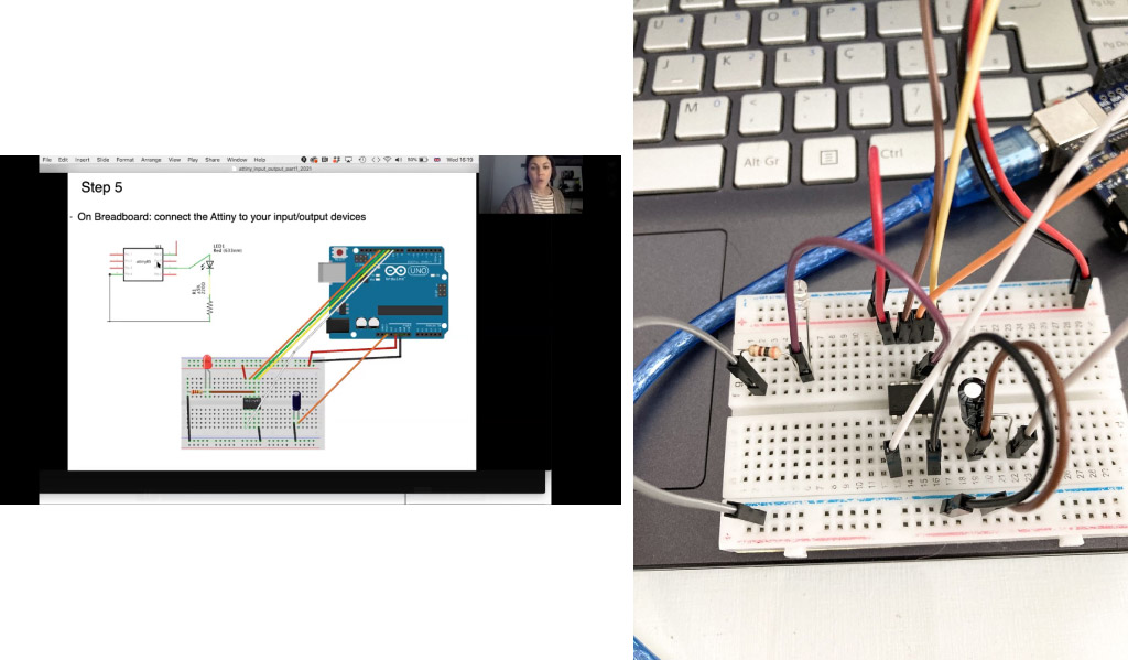
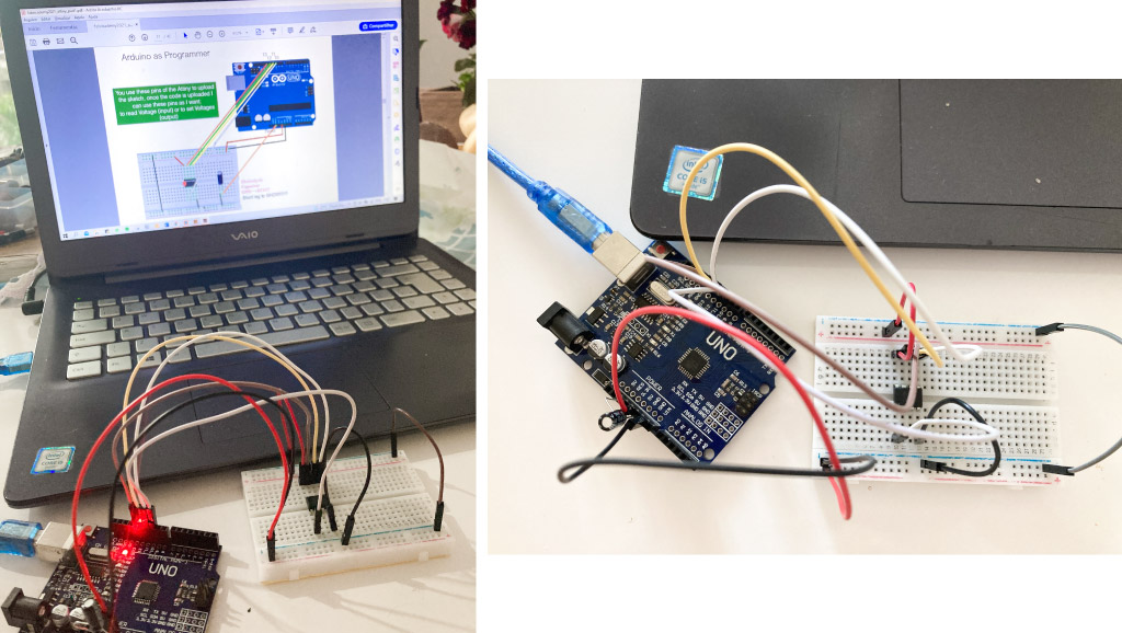
First, we assembly the circuit in the breadbord (I used the same of Emma's slides).
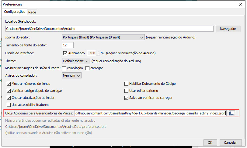
Then, we have to add the attiny board to ArduinoIDE, for this we go into file>preferences and copy and paste the link below in the correct area:
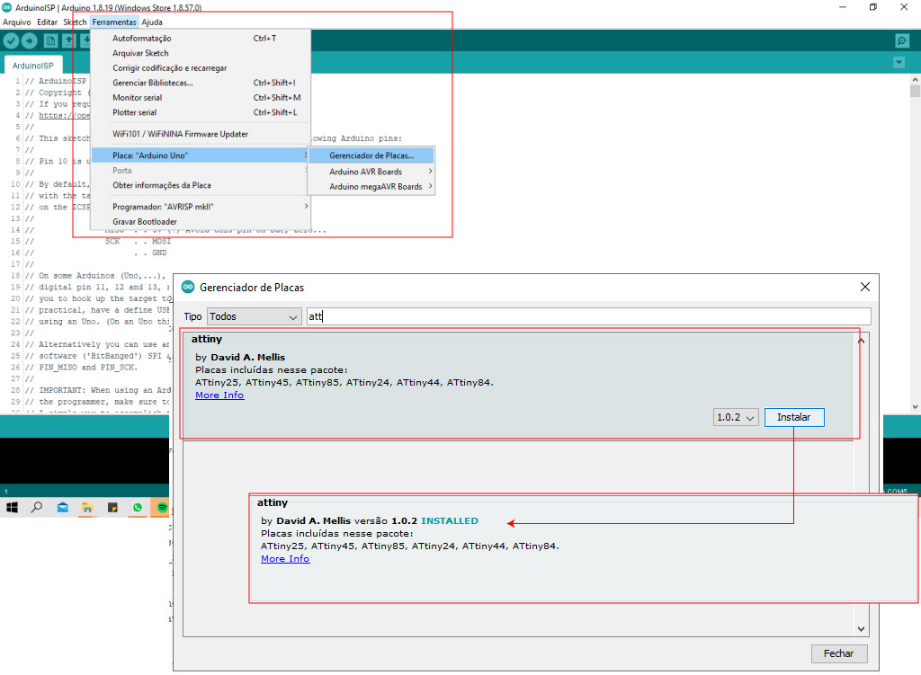
For download the board in the software, we go into tools>boards>boards manager, an window will pop up. So in the toolbar of this window we tipe "attiny", the "attiny by David" must appear, then we click in Install.
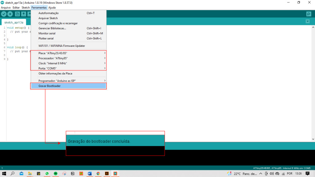
Still in tools, we can now select the correct card, processor, clock and port (in my case: Attiny25/45/85, Attiny, Internal 8MHz, COM5). When everything was selected correctly, we clicked on "bur the bootloader".
Attiny + LED
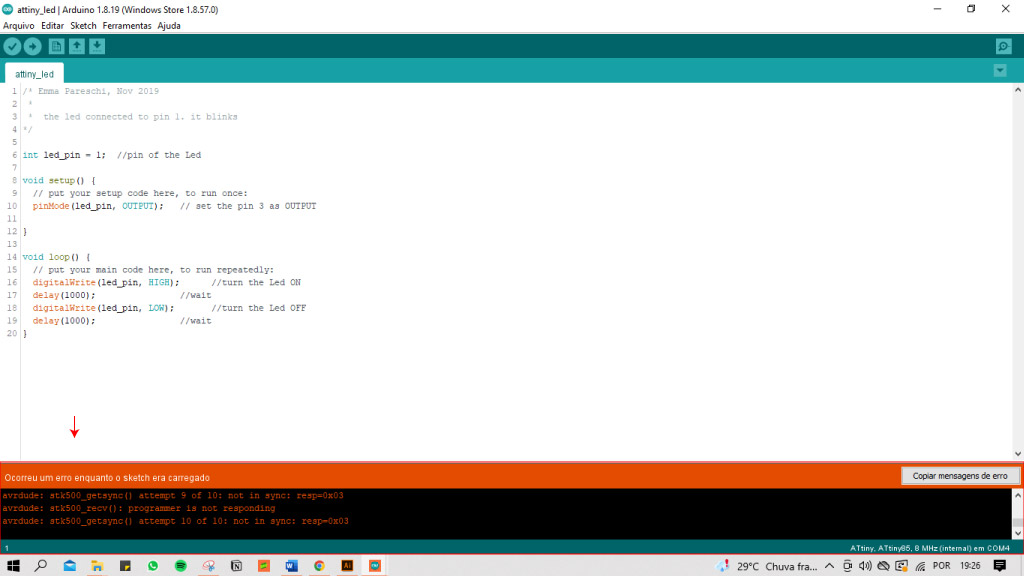
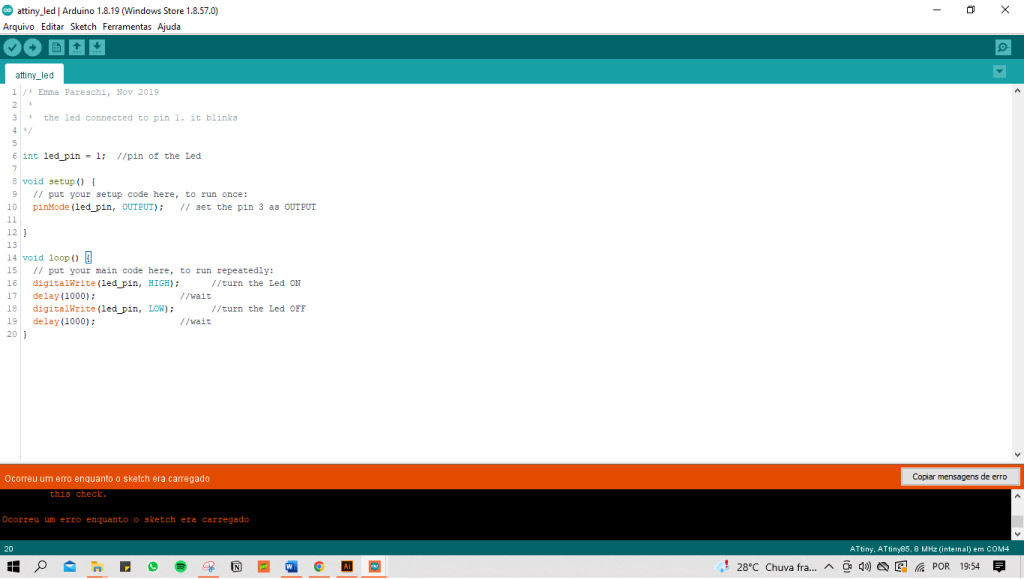
For programming one LED with the Attiny, I made again the sketch from Emma's classes, just adding one LED, 2 jumpers and one resistor.
But, when I uploaded the sketch to the board, didn't worked.
code:
/* Emma Pareschi, Nov 2019
 *
 *  the led connected to pin 1. it blinks
*/

int led_pin = 1;  //pin of the Led

void setup() {
  // put your setup code here, to run once:
  pinMode(led_pin, OUTPUT);   // set the pin 3 as OUTPUT

}

void loop() {

  // put your main code here, to run repeatedly:
  digitalWrite(led_pin, HIGH);      //turn the Led ON
  delay(1000);                //wait
  digitalWrite(led_pin, LOW);       //turn the Led OFF
  delay(1000);                //wait
}
When I checked the mattermost, Emma has suggested to one person (that had this same problem) to do the process again: Arduino as ISP, burn the bootloader and if did not word, assembly the circuit again...
So, I started again.
From the first moment, the sketch Arduino as ISP was not working as before.
Until I realized that I was selecting the wrong board, processor and port.... The Arduino UNO board must be empty in this time too.
Board: Arduino Uno; Poat: COM 5; Programmer: Arduino as ISP.
Done!
But, when I tried to upload the sketch and programming the LED, it didn't worked again.
Frustrating!
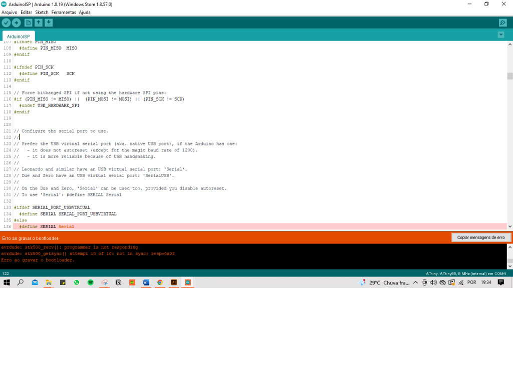
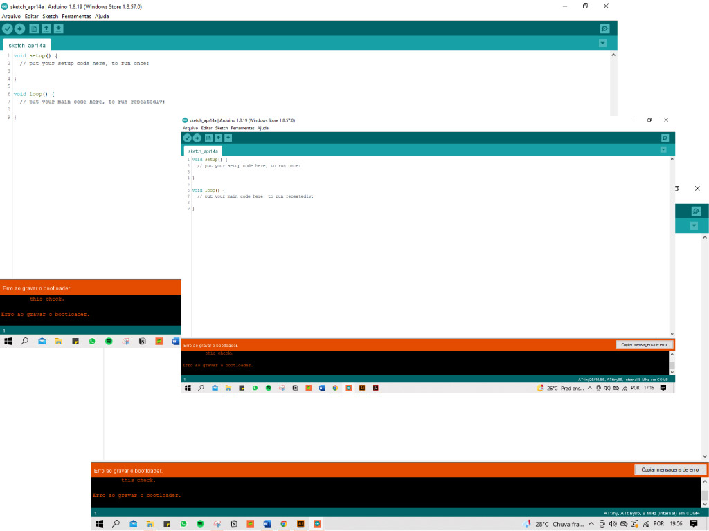
So, I made again the circuit from the slide (the one without the LED), and tried to burn the bootloader (selecting the correct port, programmer, board...).
But didn't worked as before and I have no idea why, since I did everything the same before.
REFERENCES
Digital Eyeshadow by Lulin Ding.