8. WEARABLES
For this week of Wearables, we deepen the studies on actuators and various possibilities of outputs. I realized that I was still feeling confused by some basic electronics terms, and at first I had trouble visualizing the difference between sensors (which we saw in another week of e-textiles) and actuators. So before actually starting my tests and design, I decided to study the subject a little deeper. For that, I set up a table to act as a glossary, both for myself and for other people. References can be found at the bottom of this page. :)
GLOSSARY - BASIC ELETRONICS
| What | Description |
|---|---|
| Actuator | An actuator is a component of a circuit that moves or controls another part based on input.Responsible for moving a mechanism or another part of the system, it needs at least a control signal and a power source. When the signal is sent, it responds by converting this form of energy into another (output of the circuit). |
| Arduino | hardware (board) + software (AriduinoIDE) + community. Helps us to prototyping with eletronics |
| Binary numbers | 0 e 1 (bit), low, high, false true |
| Breadboard | It is a physical support flor making temporary circuits and prototyping, and they require absolutely no soldering |
| capacitors | stores electric energy |
| Circuit | A path for electricity to flow (travels from the + to the -). A clore loop in which elétrons can travel in. It can be parallel ( Voltage Split, Current same) or Serie (Voltage same, Current Split) |
| Controller | Process the circuit |
| Data sheet | component information sheet (specified by the manufacturer) |
| Diode | The current can flow Only in a Direction. From positive (cathode) to negative (anode) |
| Eletrical current (I or A) | Rate at which electrical charge flows. Dynamic eletricity. |
| Energy - Mechanical | Cause: motion, Result: Motion |
| Energy - Thermal | Cause: different heat, Result: Motion, heat |
| Energy - Sonic | Cause: Vibration, Result: Motion |
| Fiber Optics | Light shines in one end, travels down the strand, and emerges at the other end. |
| Energy - Eletrical | Cause: charged particles (nêutrons – no charged, prótons +, elétrons -), Result: Heat, motion, sound, light. |
| Inductor | stores energy in the form of a magnetic field (we were used to build transformers) |
| LED | It’s a light source and part of the Family of Diodes. The longer leg and chamfer indicate the positive side. Cathodo is the side connected to the resistor. Different color LEDs have different forward voltages. |
| Loads | The reason we want to build circuits is to make electricity do useful things for us. The way we do that is by putting things in the circuit that use the current flow to light up, make noise, run programs, etc. |
| Multimeter (DMM) | Device that helps us measure current, resistance and other values. |
| Neopixels | Neopixels are RGB LEDs with drivers embedded in the chip. This allows them to be addressable - you can control individual LEDs on a longer strip. It lets you have Lots of LEDs and only take up three pins on your micro controller |
| Ohm’s Law | Defines the relation betwen voltage, current and resitor. V = I * R |
| Resistance (R or Ω) | The amount of material that resists the flow of current |
| Resistors (R or Ω) | Impede a flow of current and impose a voltage reduction. Color bands on the resistor indicate the resistor value |
| Schematics | are our map to designing, building, and troubleshooting circuits. |
| Sensor | Device that allows the conversion of energy from one form to another (circuit entry/input). The interaction of sensors generate an electric signal (a change of Voltage). It can be digital (0-1), or analog (minimun GND, maximum VCC - change the resistence) |
| Solenoid | electromechanical device consisting of an inductive load. When we apply a voltage it creates a magnetic field. |
| Sketch - global variables | In the programming on ArduinoIDE, declare the variables |
| Sketch - setup () | In the programming on ArduinoIDE, internalise, runs once - at the beginning, define the pins |
| Sketch - loop() | In the programming on ArduinoIDE, Running, run reapeatedly, after setup |
| Thermochromic inks/pigments | change state in the presence of heat. Once they reach a temperature, the inks become colorless. |
| Transitor | let us use a secondary power source. We use the transistor as an electrical switch.By applying a small amount of voltage to the gate using the Arduino, current can flow between the drain and the source. |
| Voltage (V) | is the difference in charge between two point |
| Voltage Divider | Is a simple circuit which turns a large voltage into a smaller one |
CLASSES TUTORIALS
basic programming: arduino + LED
After understanding some concepts a little deeper, I went on to the exercises shown by Emma's tutorials. For that, I used my first sensor of the e-textiles week. It's really exciting to see the LEDs responding to the Arduino!
Sketches from Emma Pareschi's Tutorial
1
Led blink
/*Emma Pareschi 25 Spetmber 2017
 * I turn on a led and I turn it off
 */

int led_pin = 3; //defin the pin where the Led is connected

void setup() {

 pinMode(led_pin, OUTPUT); //define pin of the Led as an output
  }
void loop() {
  digitalWrite(led_pin, HIGH); //turn the Led on
  delay(1000);                 //wait 1000millisecond
  digitalWrite(led_pin, LOW);  //turn the Led off
  delay(1000);                 //wait 1000millisecond
}
2
/*Emma Pareschi 25 Spetmber 2017
 * I change the intensity of the Led
 */

int led_pin = 3; //defin the pin where the Led is connected

void setup() {

  pinMode(led_pin, OUTPUT); //define pin of the Led as an output

}

void loop() {

  //analogWrite(pin, 0/255);
  analogWrite(led_pin, 255); //set max intensity
  delay(1000);                 //wait 100millisecond
  analogWrite(led_pin, 190);
  delay(1000);                 //wait 100millisecond
  analogWrite(led_pin, 127); //set half intensity
  delay(1000);                 //wait 100millisecond
  analogWrite(led_pin, 70);
  delay(1000);                 //wait 100millisecond
  analogWrite(led_pin, 0); //set min intensity
  delay(1000);                 //wait 100millisecond
  }
3
/*Emma Pareschi
 * we read the value of a digital sensor connected to pin digital_sensor_pin and
 * we print it on the Serial Monitor
 */

int digital_sensor_pin = 2;     //change the pin, where the sensor is connected
int digital_sensor_value = 0;   //variable in which we save the sensor voltage

void setup() {
  // put your setup code here, to run once:
  //pinMode(digital_sensor_pin, INPUT);
  pinMode(digital_sensor_pin, INPUT_PULLUP); //define the pin as INPUT
  Serial.begin(9600); // open commmunication

}

void loop() {
  // put your main code here, to run repeatedly:
  // digitalRead(pin);
  digital_sensor_value = digitalRead(digital_sensor_pin); // read the sensor

  Serial.print("the status of the sensor is: ");
  Serial.println(digital_sensor_value); //print the value
  delay(100);

}
4
/*Emma Pareschi,
 * this skecth is a modification of the example button!!
 */

int digital_sensor_pin = 2;     //change the pin, where the sensor is connected?
int digital_sensor_value = 0;   //variable in which we save the sensor voltage
int led_pin = 3; //change the pin of the Led

void setup() {
  // put your setup code here, to run once:
  pinMode(digital_sensor_pin, INPUT_PULLUP);  //initialize the sensor pin
  pinMode(led_pin, OUTPUT);   //initialize led pin
  Serial.begin(9600);

}

void loop() {
  digital_sensor_value = digitalRead(digital_sensor_pin); //read the Voltage at pin sensor

  // check if the pushbutton is pressed.
  if(digital_sensor_value == LOW){    //If it is pressed

      digitalWrite(led_pin, HIGH);     // turn the LED on
      Serial.println("the Led is on.");

  } else {                             //If it is NOT pressed

      digitalWrite(led_pin, LOW);    // turn the LED on by setting the voltage HIGH

  }
5
/*
Emma Pareschi 2020
I turn on the Leds based on the times I press the digital switch
 */

// this constant won't change:
int  sw_pin = 2;    // the pin that the pushbutton is attached to
int counter_reset = 4; //variable to reset the counter

int array_led[] = {3,5,6};  //array of led
int num_leds = 3;

// Variables will change:
int counter = 0;   // counter for the number of button presses
int sw_status = 0;         // current state of the button
int last_sw_status = 1;     // previous state of the button

void setup() {
  // initialize input and output pins:
  pinMode(sw_pin, INPUT_PULLUP);

  //set the array pins as output
  for(int i = 0; i < 4; i = i+1){
    pinMode(array_led[i], OUTPUT);
  }

  // initialize serial communication:
  Serial.begin(9600);
}
electromagnetism
To create a magnetic field we need current through a wire, and we do these making rings with copper wire. These electromagnets allow us to work with motion on Wearables. I create my magnetic fiels following Liza's presentation and Emma's tutorial.
Steps:
- Create your coil with Enamel Wire, 30 gauge.
- Wrap the end piece around the loop to secure the wire in a circle.
- Burn off the enamel and solder the ends.
- Test it using an electromagnetic and one power supply!
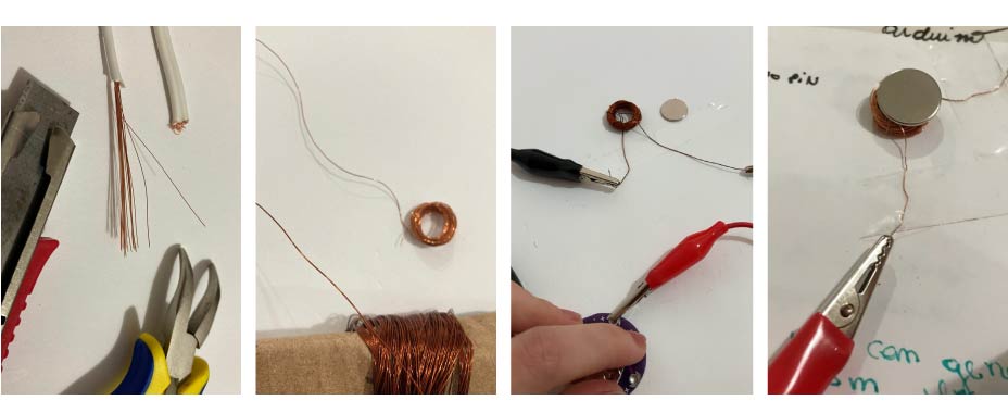
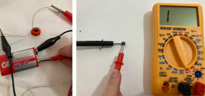
1st test: copper wire - super thin
Out of curiosity, I decided to test my magnetic field with copper wires that are not enameled, those that come inside the electrical cables used for power (1mm). So I cut the cable with the help of pliers and a knife. It was quite difficult to get the copper wires out of the plastic without them bursting, so that gave me a lot of dedicated work time for a few meters of wires.
As I couldn't get a very long length of wire, I was able to make approximately 50~60 rings. When I tested it to see if a magnetic field had formed, it didn't work (I tested it with 3V and 9V batteries). I believe because of the thickness and length of the wire used.
Anyway... I don't recommend doing this test at home! hahahah
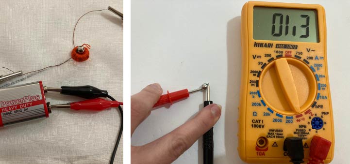
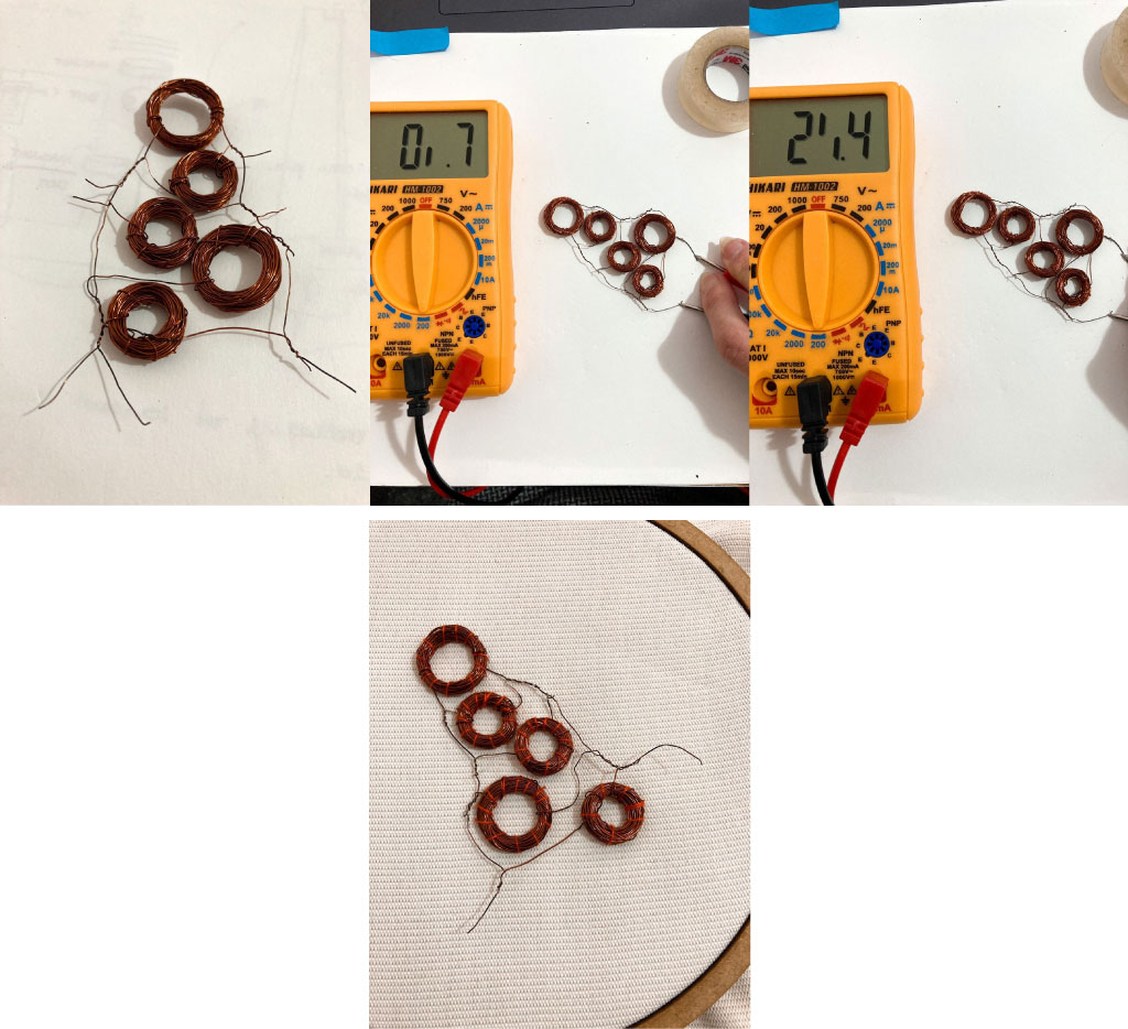
2nd test: enamel Wire - 28 gauge
So, I did the test again, this time with 28 gauge enameled copper wire (I didn't find 30 gauge), with approximately 70 rings and testing with 3V and 9V batteries... it worked!
FLIP DOTS
reference projects + concept idea
Some projects with movement caught my attention since the first week about e-textiles.
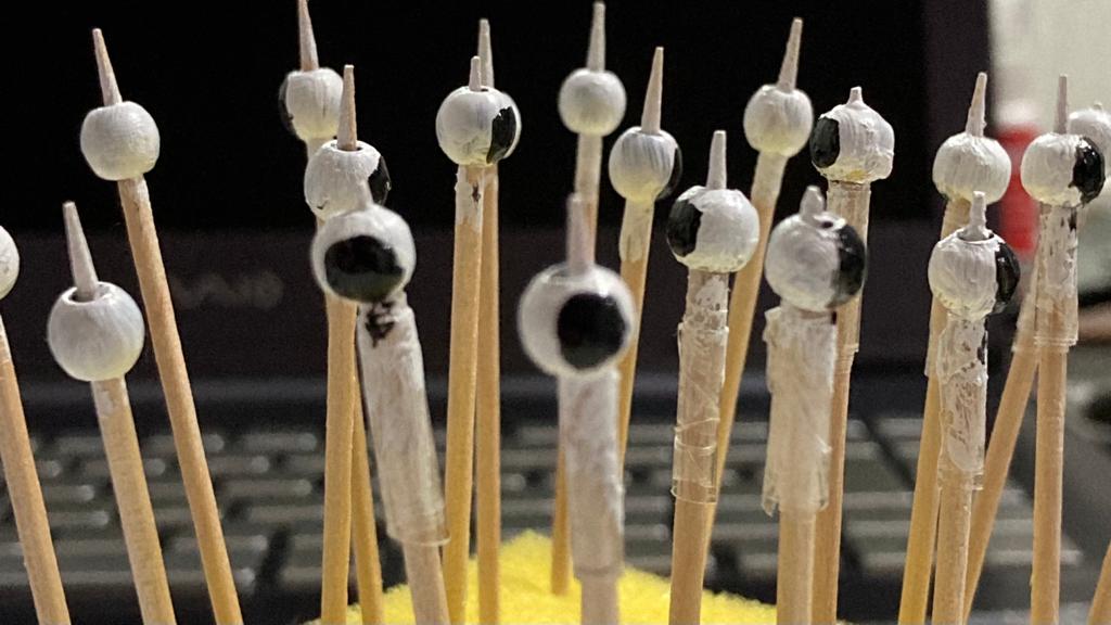
I really liked the idea of using movement through flip dots because as soon as I saw the flip dots moving they reminded me of a winking eye! And when they were integrated into the fabric with the embroidery, they reminded me of the guaraná fruit (Paullinia cupana), a vine originally from the Amazon, widely used to make soda pop. The whole idea of integrating crafts with electronics excites me, so I thought, why not make guarana that blink?!!!

guaraná fruit, image from https://blog.phebo.com.br/gastronomia-brasileira/
1st test: hematite dots
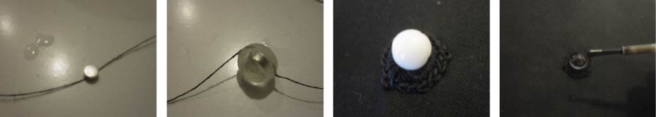
For that, to make my flip dot, I followed the steps of Lizza's Slides.
After making the copper wire rings to create the magnetic field from the previous tests...
- Embroider the loop into fabric/paper or crochet around it and sew it in.
- Solder the two wires to your fabric pads (I didn't made this step, as it was just a test, I used alligators connected to my battery).
- Sew the hematite bead into the loop with cotton trhead.
- Test it manually reversing the alligator connections to the battery!
It didn't work, I was wondering if my hematites were real and when I tested their conductivity with the multimeter I saw that they sold me fake hematites :(. Yes, I should have tested that first...
2nd test: metal dots
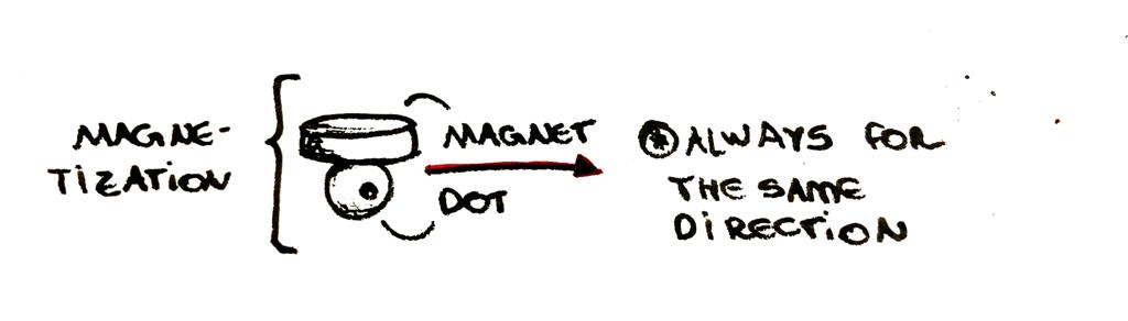
I ended up buying metal beads too, just in case... So I replaced the hematite bead with the metal bead (this time I tested the conductivity before, with the multimeter). It didn't work either, so when talking to Angela, she told me the beads need to be magnetized to work. What seems kind of obvious considering the first tests of the magnetic field were done with a conventional magnet, but I didn't really realize it.
3rd test: magnetizing metal dots
So, when looking on the internet with magnetizing metal, I found that one side of the magnet must be passed in only one direction through the metal (because it is necessary for the friction to occur in one direction only, as friction in one direction will nullify the magnetization obtained in the opposite direction). I wasn't able to photograph the process during the magnetization attempt, but it ended up not working either. I believe that because my beads are very small, which ended up making it difficult for me to pass the magnet in only one direction.
So I gave up using the purchased beads, which was sad, because I had already painted them all to look like the guaraná fruit (something I should have done after testing as well).
4rth test: handmade alginate bioplast dots
After these attempts I decided to make my own magnetized account when I saw that there was a tutorial about it on [Kobakant]https://www.kobakant.at/DIY/?p=5915. In this tutorial they used polymorph with a tiny magnet to make the shape.
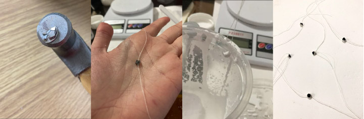
As I didn't have a polymorph, I decided to make my dots with alginate bioplastic. I don't know how or why, but after some tests with the magnet + magnetic field made with copper wire + battery, I saw that some of my magnets broke. I'm not sure how it happened, but when I saw it, they were broken, so I took the opportunity to break more and use the pieces of the magnet to make the magnetic beads.
I barely registered the process, but I followed this recipe:
| water | alginate | glycerine | coconut oil | pigment |
|---|---|---|---|---|
| 100 ml | 3g | 5g | 2.5g | some white ink |
For this, I dipped my beads in the alginate mixture, then left a few minutes in this mixture (and then rinsed):
| water | sodium chloride hydrate |
|---|---|
| 50 ml | 5g |
Once dry, I made black balls with conventional black nail polish.
Anyway, some tips:
- Place the cotton thread between two broken magnets so it is better fixed.
- Always dip one magnet at once into the mixture, either alginate or sodium chloride, otherwise they will attract and stick together.
- Mix with plastic or wooden spoon, if metal, magnet will stick to spoon.
- Leave them to dry at a safe distance, otherwise they will stick together.
My beads were a little rough because the alginate bioplastic is a little difficult to mold and it contracts a lot, but it worked!
SPEAKERS
We use speakers to make sound of a magnetic field, coil and a magnet attached. To create our own speaker, we can again make our own magnetic field. This time we do this in a spiral with some conductive material, then we add magnets to them. In this process we must consider: the width of the wire used, the coil thickness, the material, the width of the magnet and the place of the magnet.
To do mine, I followed the steps of Liza's class:
- Draw a coil on your fabric or paper. It can be any shape.
- Thread your needle with one strand of conductive thread. You can run beeswax over the end to get it through the eye.
- Tie a knot 5-6 inches from the end.
- Come up through the center of the piece of fabric.
- Stitch around the coil, making sure the conductive thread lines of not touch each other. Use a straight or couch stitch.
- Make sure the extra 5-6 inches of thread doesn't get sewn into the coil! We need to keep them separate.
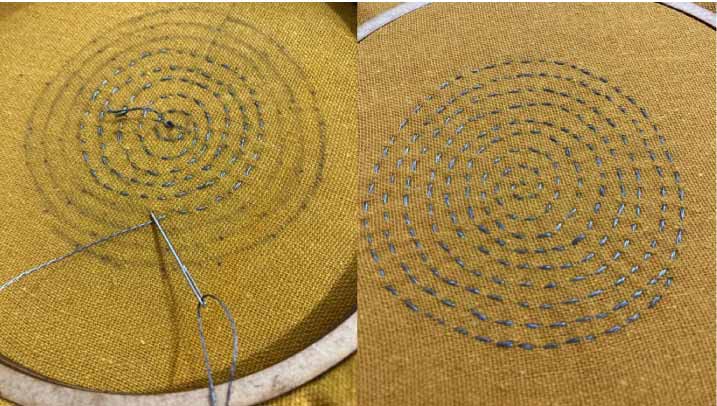
I made it using linen fabric mixed with cotton and polyester for the support and conductive thread. I left approximately 5mm of distance between one wire and another on the coil.
CIRCUIT DRIVER
To generate outputs with actuators, we need another power font suply because the arduino cannot provide us with this. Assim, precisamos construir um circuito externo que nos permita usar uma power source secundaria, chamamos isso de circuit driver. So, we need to build an external circuit that allows us to use a secondary power source, we call it a circuit driver. For this, we use a transistor (in our case an N channel Mosfet) as an electrical switch and a diode to protect the mosfet.
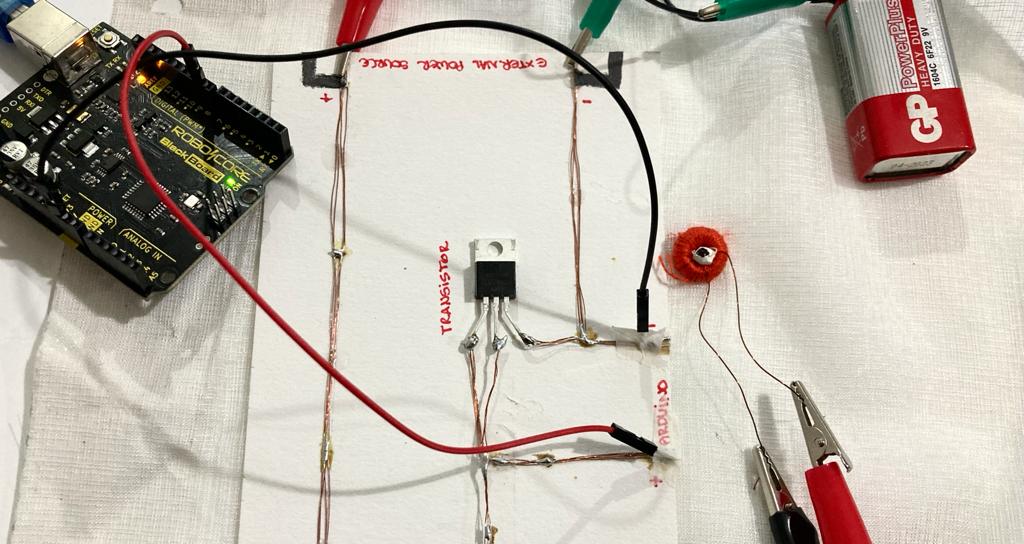
1st test - copper wire
In Emma's tutorial and Liza's presentation these circuits was made with copper tape. As I didn't have it at home, I decided to test it with the copper wires that I extract from a power wire in the previous tests.
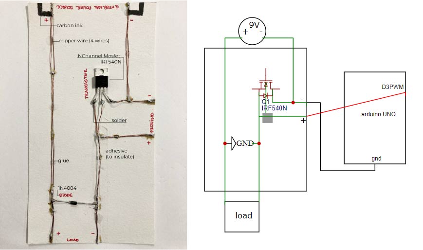
However, when I connected to the arduino and tried to make my flip dot blink, it didn't work. When measuring with the multimeter to see if all the connections and components were working, I found that the resistance was too low (0.1 ohm) as the copper wire placed is too thin. So I believe that was the problem.
2nd test: aluminum paper
As my first circuit driver didn't work, I did a second test with the same circuit, but this time with aluminum foil to make the current flow. For this, I cut 7mm aluminum foil strips, made the connections between them with white glue (taking care not to insulate the material). When trying to solder the components, I had a lot of difficulty with the aluminum, they didn't fix it at all... so I ended up putting a tape over the solders.
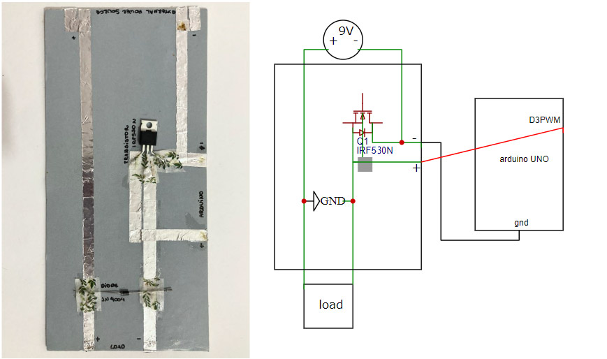
in these circuit driver I used IRF530N
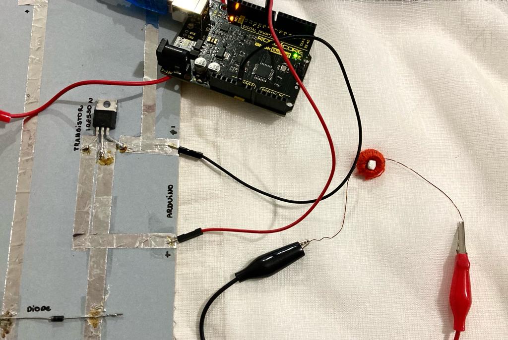
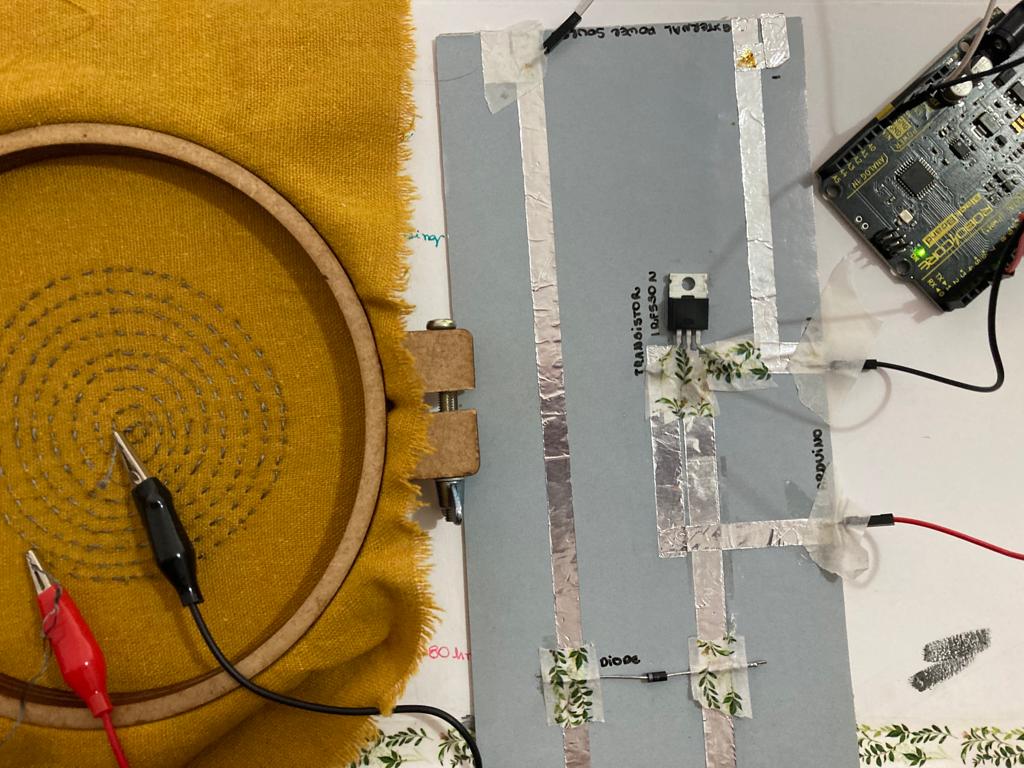
This circuit didn't work either :(
After clearing some doubts with Emma, she said that aluminum is not usually very easy to solder because it dissipates heat very quickly, in addition, the connection of the circuit with the arduino using tapes makes it very unstable. I ended up testing soldering the components one more time and joining them to the arduino using alligator clips but it didn't work again.
3rd test: breadboard
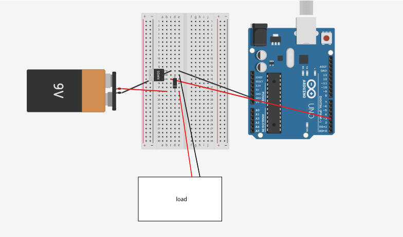
Iane gave me the brilliant idea of testing the circuit on the breadboard. For the test, I used this sketch:
1 sketch some changes to Emma's led blink sketch
/*flip dots
1 sec
 */

int led_pin = 3; //defin the pin where the Led is connected

void setup() {

  pinMode(led_pin, OUTPUT); //define pin of the Led as an output


}

void loop() {

analogWrite(led_pin, HIGH); //turn the Led on
  delay(1000);                 //wait 1000millisecond
 analogWrite(led_pin, LOW);  //turn the Led off
  delay(1000);                 //wait 1000millisecond

}
I also tested the speakers with two sketch examples:
2
/*Emma pareschi 2020
 * I generate a sound on a speaker, frequenzy of 1000Hz
 */

const int speaker = 3; //buzzer to arduino pin 3


void setup(){

  pinMode(speaker, OUTPUT); // Set buzzer - pin 3 as an output

}

void loop(){

  tone(speaker, 1000); // Send 1KHz sound signal...(from 20 to 20000Hz)
  //tone(pin, frequency);
  delay(1000);        // ...for 1 sec
  noTone(speaker);     // Stop sound...
  delay(1000);        // ...for 1sec

}
3
/*

  Melody

  Plays a melody

  circuit:

  - 8 ohm speaker on digital pin 8

  created 21 Jan 2010

  modified 30 Aug 2011

  by Tom Igoe

  This example code is in the public domain.

  http://www.arduino.cc/en/Tutorial/Tone

*/

#include "pitches.h"

// notes in the melody:
int melody[] = {

  NOTE_C4, NOTE_G3, NOTE_G3, NOTE_A3, NOTE_G3, 0, NOTE_B3, NOTE_C4
};

// note durations: 4 = quarter note, 8 = eighth note, etc.:
int noteDurations[] = {

  4, 8, 8, 4, 4, 4, 4, 4
};

//vaiable speaker pin
const int speaker = 3; //buzzer to arduino pin 3

void setup() {

  // iterate over the notes of the melody:
  for (int thisNote = 0; thisNote < 8; thisNote++) {

    // to calculate the note duration, take one second divided by the note type.
    //e.g. quarter note = 1000 / 4, eighth note = 1000/8, etc.

    int noteDuration = 1000 / noteDurations[thisNote];
    tone(speaker, melody[thisNote], noteDuration);

    // to distinguish the notes, set a minimum time between them.
    // the note's duration + 30% seems to work well:

    int pauseBetweenNotes = noteDuration * 1.30;
    delay(pauseBetweenNotes);

    // stop the tone playing:
    noTone(8);

  }
}

void loop() {
  // no need to repeat the melody.
}
My bead ended up not running as much as when I tested it manually, so for the final piece I must make bigger rings for my electromagnetic field. But after so many attempts, this result made me very happy :3 The first test using sketch 2 and the speaker generated a very low noise, to be able to show in the video I recorded the part with the cell phone and added the image capture, then I increased the volume in DaVinci Resolve. This third sketch didn't work, I suppose because it's a small, weak magnet. For the final piece I will use a bigger one.
Following Lizza's slides, I also tested the speaker with a second circuit, without using the external power source, only 5V from the arduino board. But this time neither the first or the second sketch worked.
FINAL SAMPLE - FAILED! :(
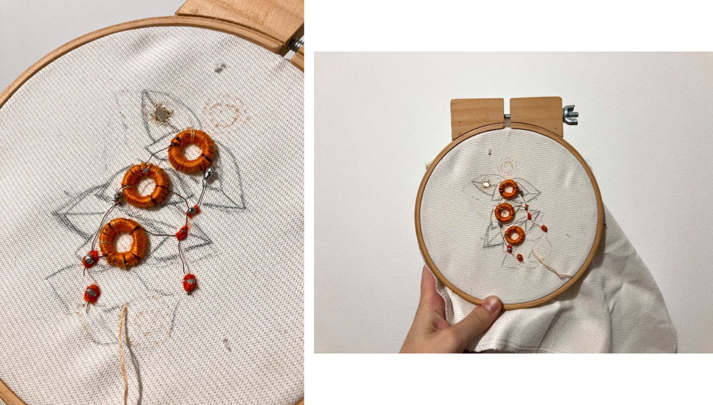
paralel circuit - flip dots - test 1
For my guarana embroidery, I made a parallel circuit of copper wires to receive my embroidery. However, in my first test, only one flip fot was moving, I suppose because of the size of the holes.
Still, I tested this embroidery sewn onto the fabric to see if the flip dot worked, but it didn't... (videos below).
paralel circuit - flip dots - test 2
So, I redid the circuit in parallel, leaving the copper holes a little bigger. It was quite difficult to solder each part of the circuit because copper doesn't stick well, but this time it worked.
Tests - paralel circuit flip dots from Brunna Ramos on Vimeo.
However, when doing my final embroidery, the threads (which had received several soldering attempts) were very fragile and some ended up breaking... when trying to resolder them I ended up burning the embroidery fabric.
IDEIA - for some day...
I intend to redo this project someday, I discovered the existence of sound sensors for Arduino... the idea is that the speaker embroidery emits a sound (tropical country - jorge bem jor) - input, and the guarana flip dots move as output of the sound emitted (however, I think that for this one I will test with the magnetized hematites).
REFERENCES
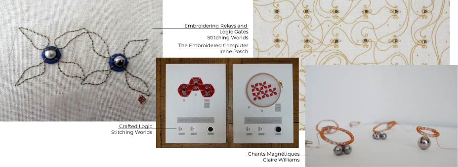
reference projects
Embroidering Relays and Logic Gates
overview: electromagnetic actuators
hants Magnétiques - Claire Williams
Soft speakers - digital embroidering
content of the glossary
resistor and colors code - in portuguese
Basic eletronics tutorial - fabricademy
Hpw to use a multimeter - sparkfun
Voltage, Current, Resistance, and Ohm's Law - Saparkfun
Transistors, Relays, and Controlling High-Current Loads