PROJECT TESTS, ALIGNMENTS AND ASSEMBLY
WHAT I WILL TEST?
Before I start my tests and frankenstein's, I decided to schematize what I'll properly test to visualize what I have to buy and schedule in the lab. This table will change in the path of my tests, but it's an way to organize myself.
| What | Points to observe | Considerations |
|---|---|---|
| Modules | 1- find vector of Brazilian hydrographic regions; |
|
| Materials (torso) | thinking about the soft robot... Will biosilicone break up with water? | |
| Soft Robot | 1- How will the internal structure of the soft robot + modules work?; 2- Soft robot inflates/deflates well with the chosen material?; 3- Programming on the arduino: inflate/deflate on the beat of the heart; |
|
| Colors interactions | 1- what colors will i use? From what materials?; 2- How do they interact with each other?; |
Note: The underlined texts were steps that were simplified or eliminated during the prototyping process.
This documentation page will show both the testing process and the final assembly process of the product, since due to the time these two things happened together. For example: when a test was successful, I went to the final execution of that step while other tests from other parts happened at the same time.
materials to buy/arrange
- thin tubes;
- medium thickness tubes;
- vacuum/air pump (do prior research);
- manual pump (for tests);
- T connector (for the soft robot);
copper tape;biosilicone materials (gelatin/agar, glycerin, water), silicone (explanation further below);textiles (animal fibers/vegetal fibers);- vinyl (for vectors/soft robotics tests);
- shredded textile waste;
- conductive thread/wire;
- 3d printed mold (for soft robot);
- Dc power supply adapter or rechargable battery;
- components for the circuit (do prior research);
- ... continue ...
SOFT ROBOTICS
previews research
Soft Robotics is an important part of the design as the contraction will take place through this soft internal structure attached to the torso. As I had a bit of trouble during week 12, I ended up doing some research on soft robotics in art and similar projects to find some movement inspiration for my work.
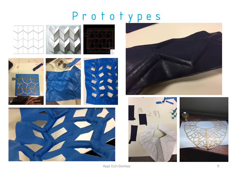
Ayse's final project caught my attention due to the contraction movement, as I want to do something similar in my project:

Serena project also was a good reference for me:
Another Fabricademy Final Project involving Soft Robotics:
I ended up delving into the research of different actuators to think about what the structure behind my torso could be responsible for the contraction of the model on the website Soft Robotics Toolkit.
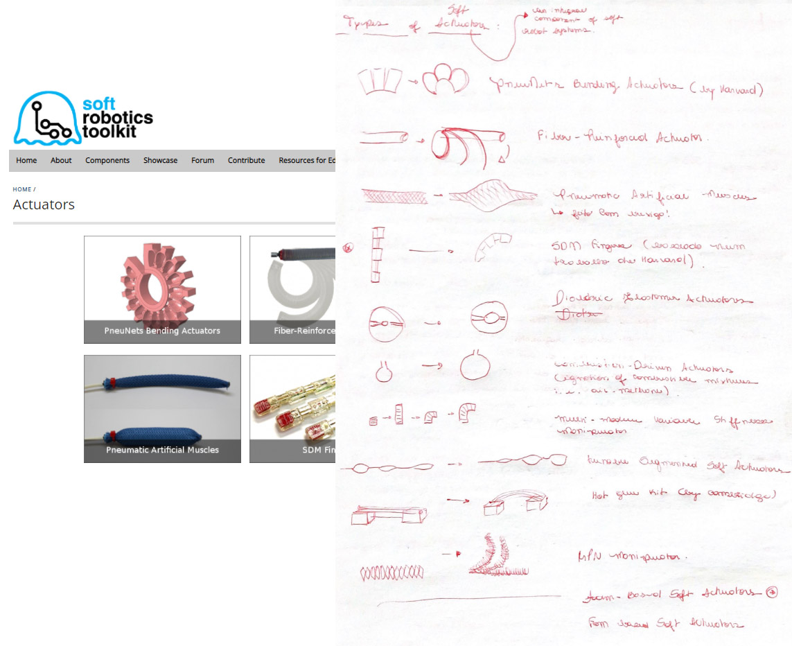
But, I ended up finding this description of shapes for contraction on the slide of Adriana Cabrera's class in Soft Robotics week, which reminded me of the Under my Skin project.
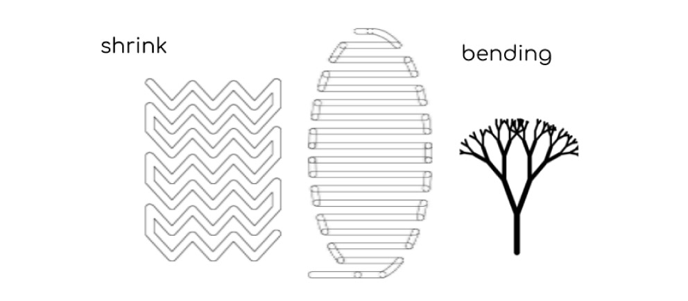
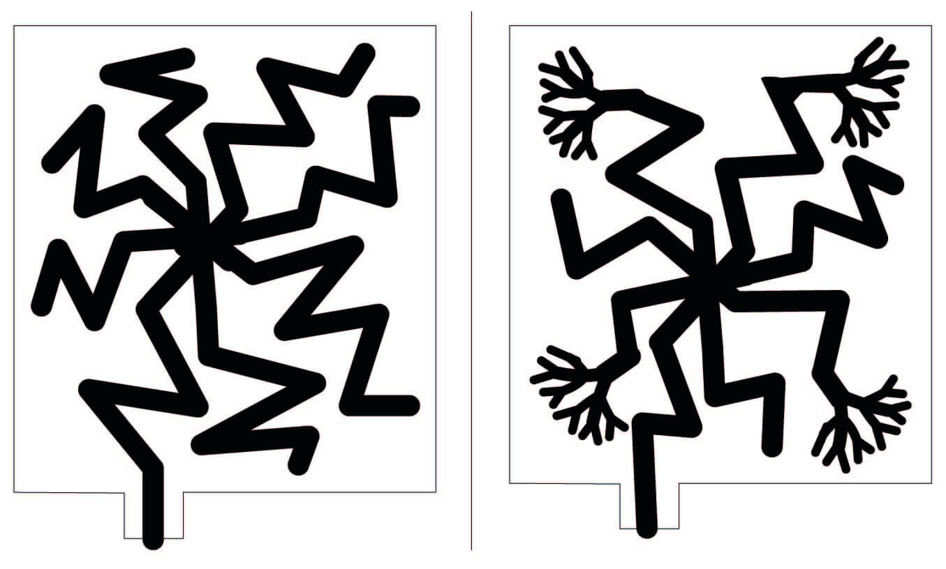
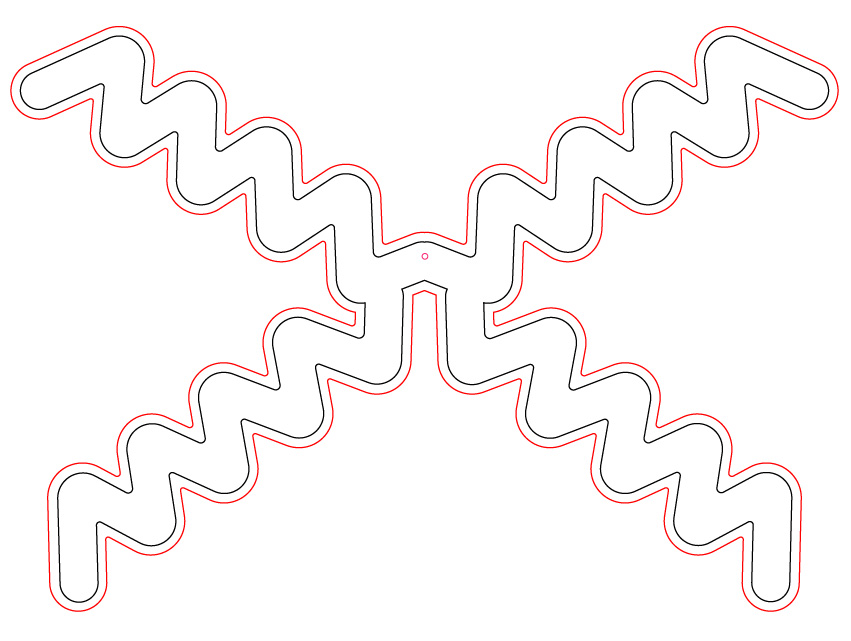
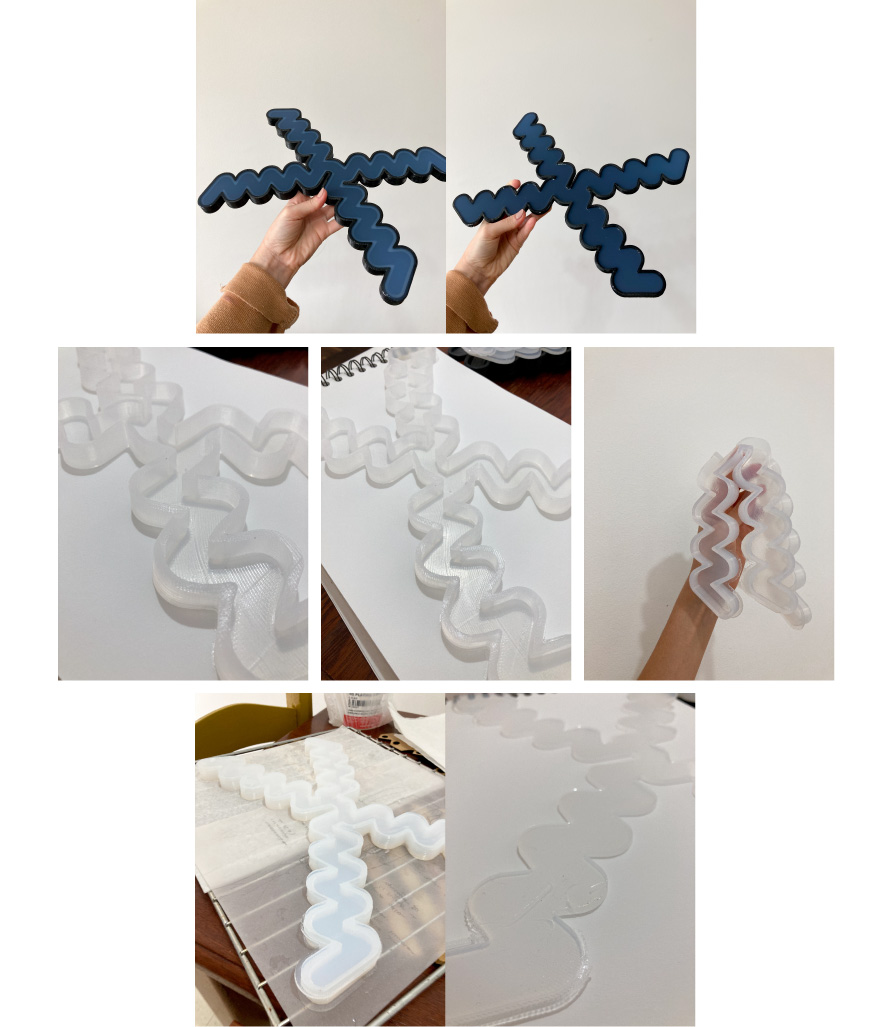
So, inspired by both Adriana's slide and Ayse Esin Durmaz's project, I decided to test these 4 variations of torso shapes:
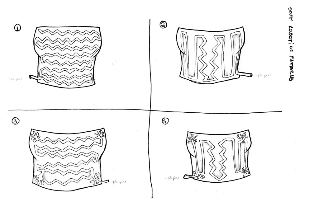
Two of them (the ones on the bottom) have the shapes for bendind, to see how the torso will behave at the ends.
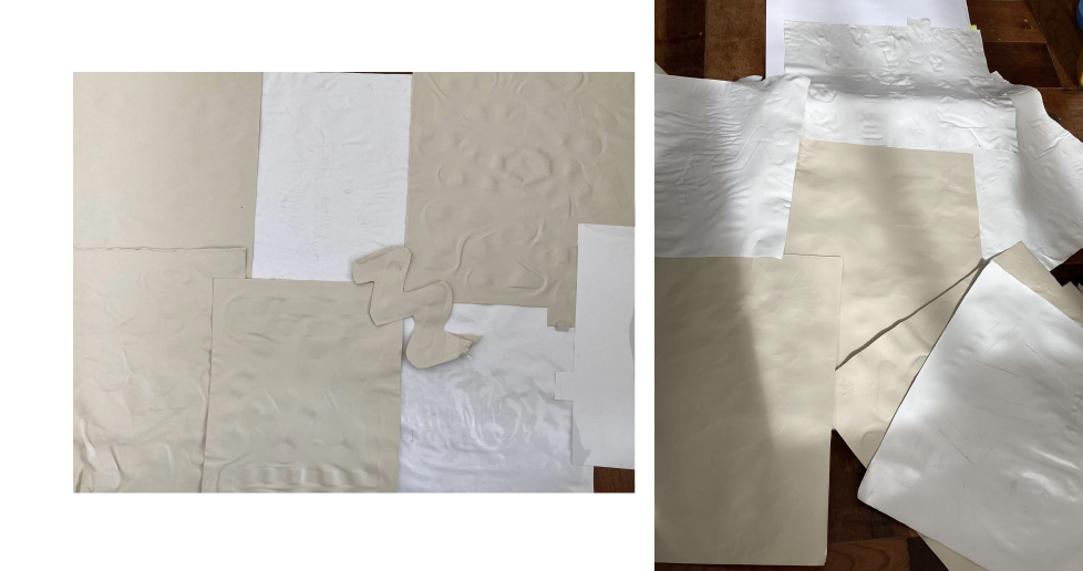
I'll test it on vinyl first, just to check and visualize motion potentials (without being parameterized from the torso, I will test first in square formats of 20 x 20 cm). The chosen vector will undergo a second test in biosilicon silicon, which is the material I intend to use (before the parameterizing on torso).
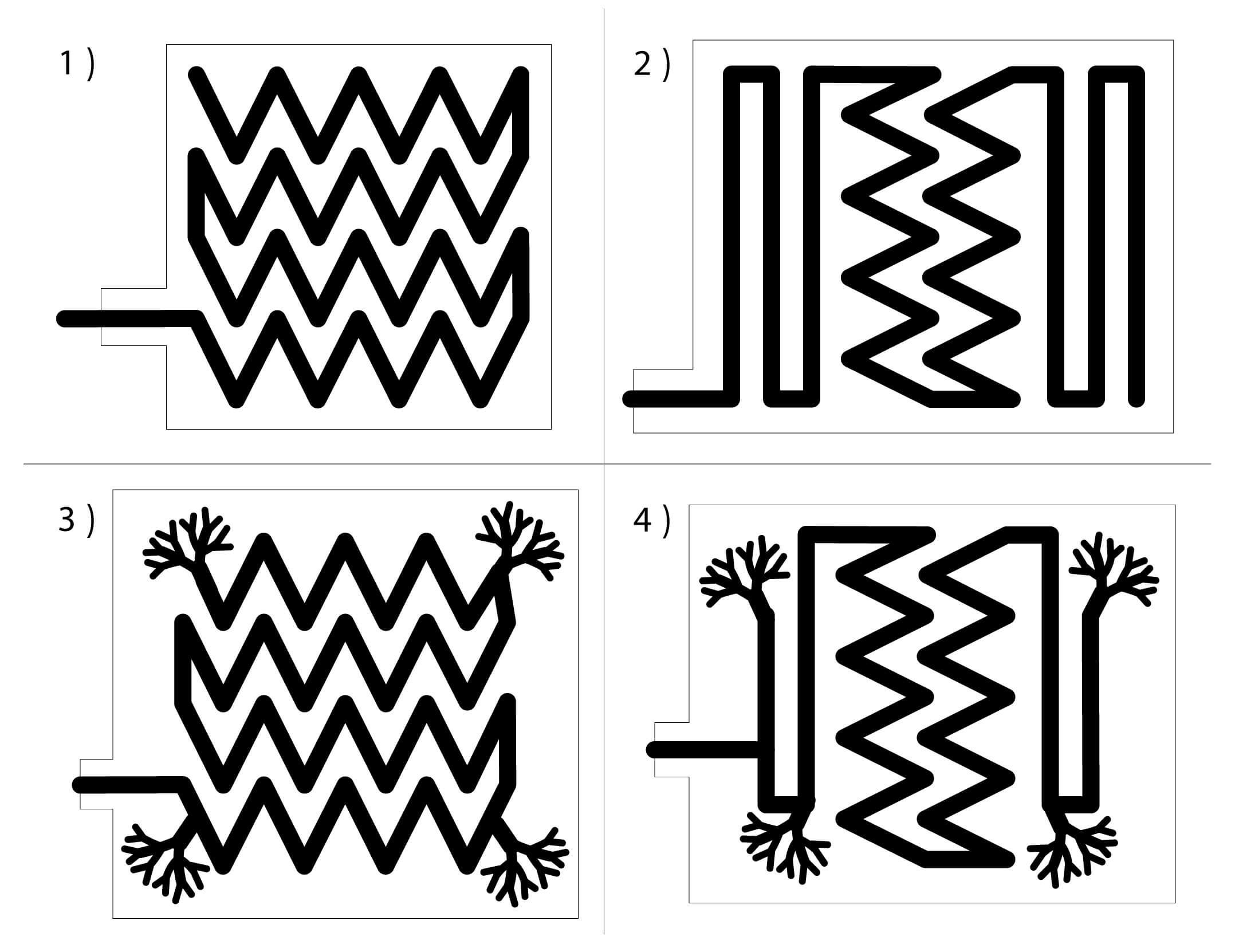
Angela commented that I could think of a more organized distribution of the vectors, maybe in a radial way, since they will be arranged on a torso and represent the heartbeat, so I made this vectors for testing too:
assembly and tests - vynil
These was the vectors that I chose to test after my research, I made all of them in Illustrator. I use the vinyl that left from the soft robotics week, it's a thin one and not so indicated for these projects, but I decided to test with it anyway.
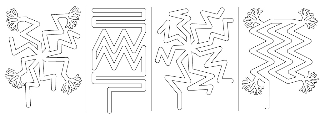
For cut the vinyl parts I used the plotter machine, and for the paper internal part I used the laser cutter machine (remembering that the internal part must have 2 papers).
Even ironing my tests, they didn't work as they didn't inflate as I would have liked. They had a lot of airflow due to the vinyl being too thin (Adriana had already warned me about this problem, but I was insistent).
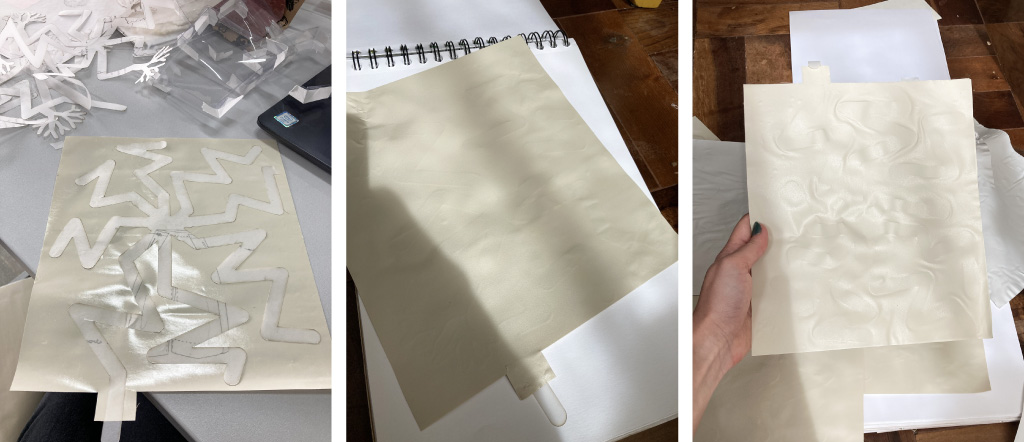
So, I bought another vinyl, this one is thicker and suitable for printing on textiles. But with this type of vynil, I had another problem... The parts did not stick together, even ironing a lot! I don't know if it's the quality of the vinyl I bought (since it was just a movement test, I looked for the cheapest one).
Here we can see another problem: I forgot to put 2 papers inside!
So, even doing a lot of tests, I didn't get a concrete result of what would be the best vector to move my torso through the vinyl tests.
3d printing - silicon and biosilicon
Talking to Angela about all my problems with vinyl, she suggested to me make directly my final soft rotobot with silicon/3D printing due the time (cause I spend a lot of time testing the movement with vynil). At this moment, we also spoke about what material to use in my torso (this'll be explained better bellow) and after few points discussed we decided to opt for the normal silicone casting instead to use the biosilicone one (because of the water and the resistence).
So, with all this aligned, I went for 3D modeling.
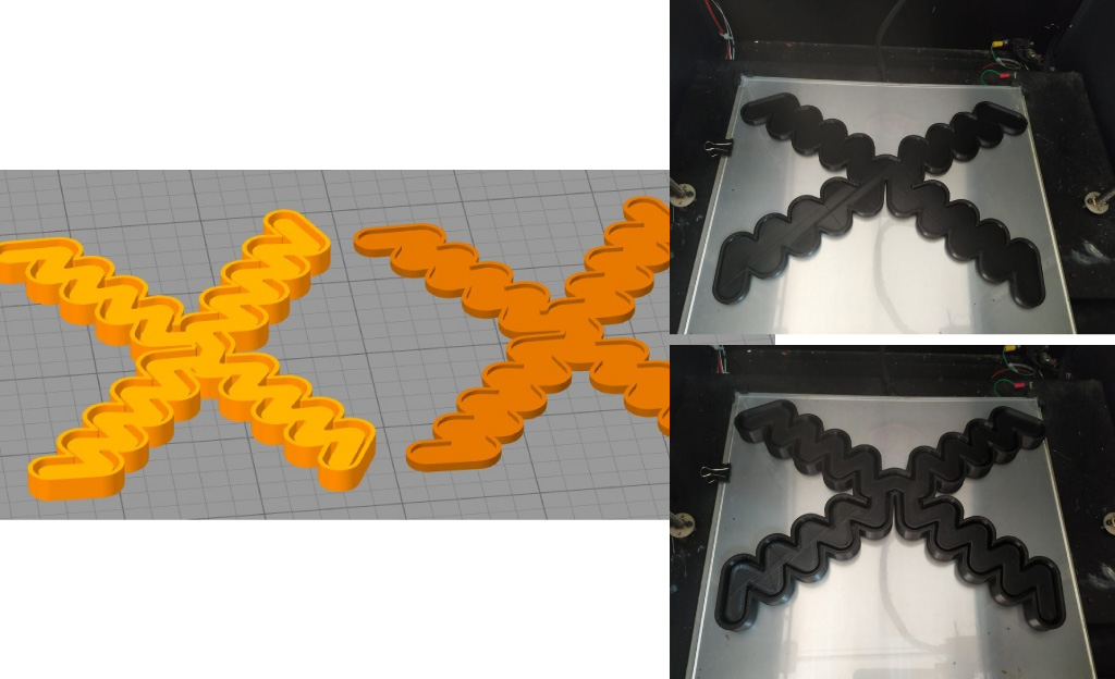
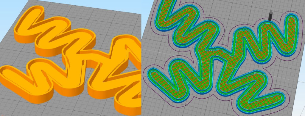
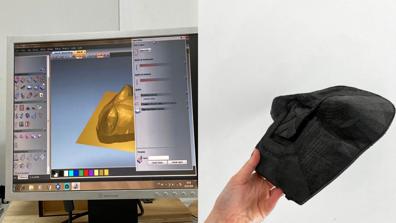
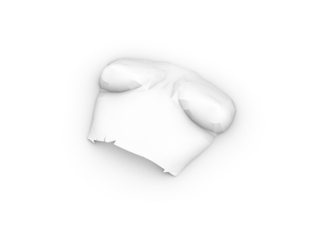
1st try - mold
I made de base of the vectors in Illustrator (cause I have more aptitude) and then I extrute the forms on Rhino. The space for the wall in silicone is about 3mm +-.
mold:
cap of the mold:
This week I didn't have access to the laboratory because of a fair they were organizing, so I had to send it to a company to print.
I asked to print with with a little fill, not 100%, as it just a mold for casting. It was printed in ABS (to be possible to bake).
casting silicone
I didn't found the Ecoflex silicone to buy, so Angela indicated to me this one:
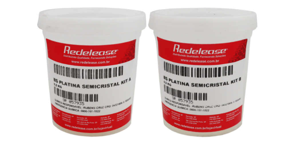
Descriptions from the manufacturer:
Semi-Crystal Platinum Rubber is a two-component elastomer, vulcanizable at room temperature, which results in an elastic and extremely resistant product, in addition to being non-toxic, suitable for making flexible and super-resistant models [...]; In addition, its incomparable resistance to any other type of existing Silicone Rubber, qualifies it to serve as a mold for mechanically or chemically aggressive products (PU, Epoxy, Parts that are difficult to demould, etc.)
-
Hardness after healing: Shore A 12;
-
Working time: Up to 60 minutes;
-
Partial curing time: About 10 hours;
-
Total curing time (when it may suffer more aggressions): About 24 hours (room temperature)
-
Mixing Ratio, A:B 1:1 (recipe)
ADVANTAGES:
-
Tested and Certified to ISO 10993-1 and USP Class VI for biocompatibility;
-
Excellent fluidity; low viscosity;
-
High biocompatibility;
-
No by-products from curing the product (does not contaminate);
-
Relatively fast curing time, at room temperature, without shrinkage, which can be accelerated by the application of heat (temperature rise);
-
Semi-crystal translucent product, with excellent tear resistance;
-
Great tensile strength;
-
Represents the most advanced in terms of technology, in the field of molding, copying, modeling and confections in Silicone Rubber;
-
To accelerate the curing, it is possible to resort to increasing the temperature;
-
Above 100 ºC the product cures quickly.
APPLICATIONS.
Molds: Non-toxic and extremely resistant flexible molds [...];
- Mechanically and chemically resistant molds (For casting Epoxy Resins, PU, pieces with a format that makes demoulding difficult, etc.);
Clothing:
- Manufacture of flexible, resistant and transparent artifacts (Orthopedic Prostheses, Sex Shop Items, Crafts etc.);
Secondary applications:
-
Decoration items
-
Molding of Sculptures and Figurines;
-
Furniture: Molding of Furniture or Decoration elements;
-
Civil Construction: Pre-Manufacture of Decorative Elements and Restoration;
-
Jewelry: Molding and Replacement of pieces in Polyester, Acrylic etc.;
-
Diemaking and Prototyping: Reproduction of Industrial Molds and Matrices;
-
Crafts: Forms for Composition of figures in Biscuit, Solid Soaps, Candles, pieces in Plaster etc.;
-
Dentistry;
-
Orthopedics;
-
Others
PROCESSING
For the vulcanization and curing of BS - Platinum Semi Crystal A / B, components A and B must be mixed in an exact proportion of 1:1 by weight. It is recommended not to change this ratio Both components are supplied ready to use. Both components must be homogenized very well, preferably using a mechanical mixer. To avoid the presence of air bubbles inside the vulcanized rubber, it is recommended to apply a vacuum immediately after mixing.
CONTAMINATION AND INHIBITION The platinum system can be inhibited by contaminants such as:
-
Tin derivatives (ex: tin system catalysts, etc.)
-
Amine derivatives (eg epoxy resin catalysts, etc.)
-
Sulfur derivatives (eg vulcanized rubbers, certain dyes, etc.)
In this way, care must be taken in relation to the packaging and utensils (spatulas, stirrers, reproduction molds, etc.) used in the processing of this rubber. It is advisable to define and segregate the packaging and utensils that will be used in the exclusive handling and processing of this type of rubber.
STORAGE AND STORAGE
-
Store both components in a dry place away from direct sunlight;
-
Adopt cleanliness and hygiene procedures after handling any chemical product before meals and at the end of the work period;
-
Storage of material beyond the expiration date on the label does not necessarily mean that the product is no longer fit for use. In this case, we recommend testing the product according to the needs of the application.
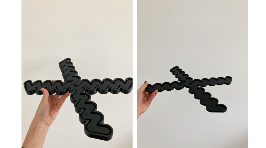
So, to make my first soft robot try I made the 50:50 mixture and then I poured the mixture into my mold. I poured slowly to avoid bubbles, but I waited a while for them all to come out and with the help of a pin I popped what was left. For curate this I put the mold in the oven for about 15 min in the lowest temperature of my oven (180 degrees), to make it a little cooler I put a wooden spoon on the door to prevent it from closing completely). I was afraid the abs would melt but it worked. First I made the base, then I made the lid and joined the parts with silicone and with the help of a brush. This was not the best way to glue the parts together as it had several air leaks along the model and it didn't inflate as I would like.
This mold turned out too big for my torso, and the folds didn't bring as much movement as I would have liked. The walls were also quite thick so the model was quite thick. So basically making the soft robot straight without silicone testing didn't work.
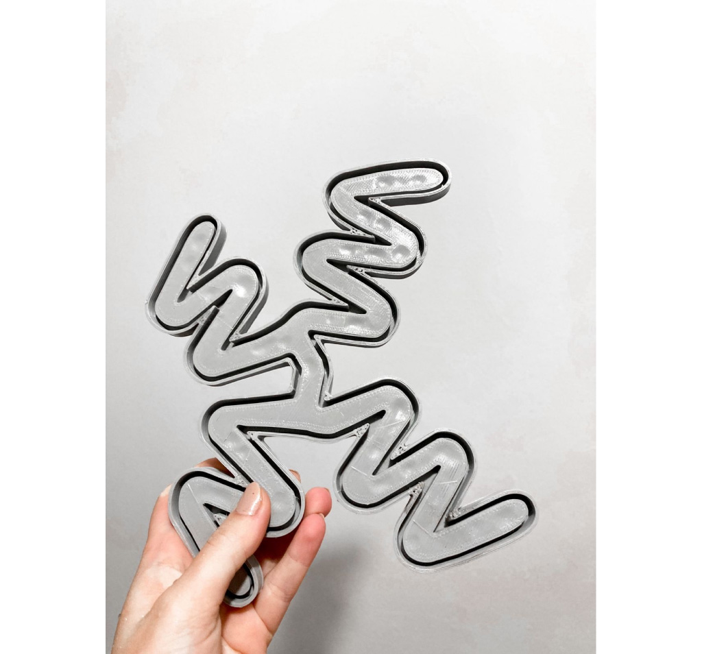
2nd try - mold
I needed to make a new mold, this time I considered one where the folds could be bigger, the walls thinner and the product overall smaller to fit my torso.
I made the same process as before: first I drew the vectors in Illustrator and then made extrude the forms in Rhino.

mold:
the cap of the mold:
I was not able to print this mold in the lab for the same reason as the previous mold, and as my time was short, I asked the company that did the work to put only the minimum fill so that the part could be printed, for the printing to be faster.
Final mold:
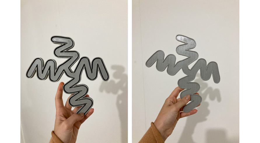
Also printed in ABS.
casting biosilicon
As I had already spent a lot of silicone on my mold that went wrong and I needed to save silicone for my final mold (and a little more if it went wrong), I decided to do a first test with biosilicone in order to verify the inflability and movement.
I used the recipe indicated in class during the soft robotic week, and heated it for a few seconds in the microwave (a few times).
| Gelatine | Glycerine | Water |
|---|---|---|
| 2 parts | 2 parts | 1 part |
recipe
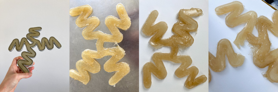
Unfortunately this test also didn't work since the biosilicone had a lot of air flow and after handling the piece a lot it ended up tearing.
casting silicon
So, I had to take a chance with the rest of the silicone I had.
But this time, I decided to join the base and the lid in a different way:
First, I made the silicone base the conventional way and baked the mold to cure. Then, instead of making the lid, baking and then joining with the base using more silicone, I baked the lid with the base part (dry) right above the mold in the oven (with the silicone still wet in the mold). So the base part was baked 2 times and the lid once.
This way worked much better, but I had another problem... As my mold was just with 10% filled, the plastic began to melt and transfer heat to the silicone, which bubbled in the oven (I only found out when I removed the cured mold).
So, even though the joining of the parts worked, the bubbles didn't allow it not to have 100% airflow and I had to give it further finishes with a brush to (only!) close a hole. As there were many bubbles, a friend of mine helped me to find out which bubble was responsible for the unwanted air leakage (it was a little difficult to find out).
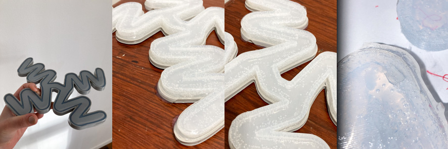
In the image bellow we can see the mold a little bit melted:
Because of this problem, the finish of my final mold was not 100%, but I decided to use it because I had little silicone left.
All files can be dowloaded here.
ELETRONICS AND PROGRAMMING
research: vacuum/air/water pump/motor and programming
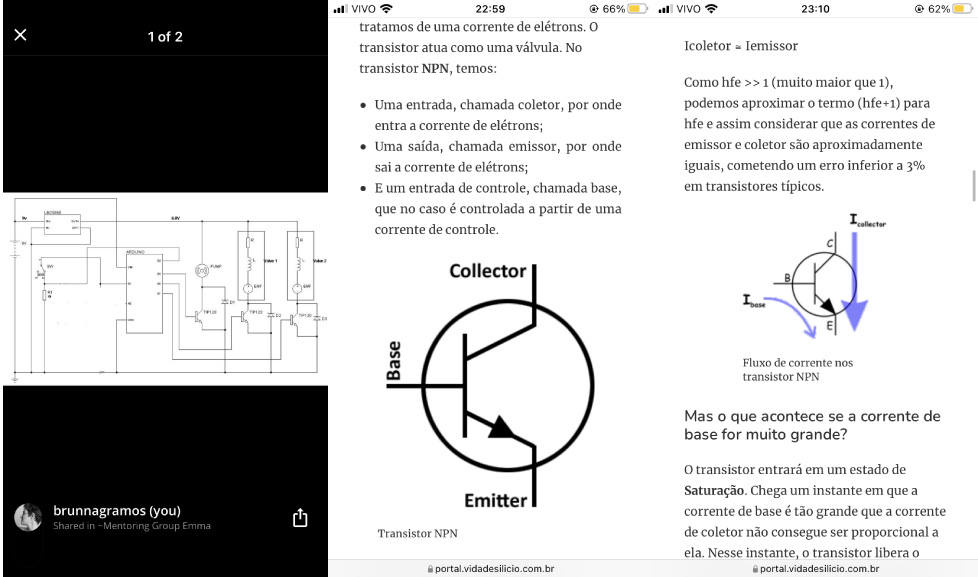
To understand a little about programming, I revisited a documentation that Adriana sent me during soft robotics week.
The documentation consists of an explanation of a circuit that works for any soft robot with pressure between 0-60 Kpa (which can work in several air channels or in a soft robot).
The system consists of two parts: 1) embedded control board and 2) home for pumps, etc.
For each pump (pressure source), two solenoids are needed (one for vacuum and one for air).
The pressure range of the pump and solenoid valves are between 0-6psi, and to scale up we need to change using a high pressure pump and solenoid valves.
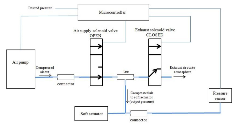
 images from Adriana's documentation
I have some doubts about this scheme. What is connector? And Tee? Can I not use the pressure sensor and just a switch? Emma answered these questions... 1) the connector and the tee are the tubes and the T for connecting the tubes. 2) She said that I can use a switch!
In the documentation, she describes in detail the materials needed, as follows:
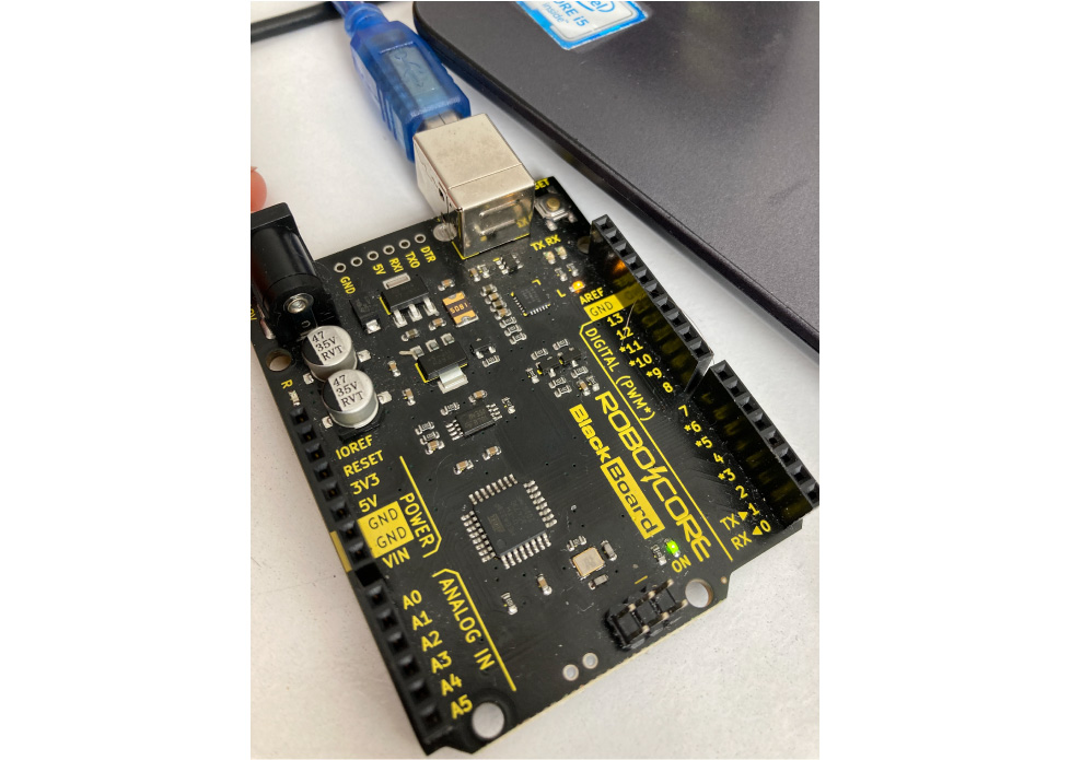
- 1 Arduino or other microcontroller (she uses Nano, can I use UNO? Emma said yes!);
- 3 TIP120 (Transistors);
- 3 1N001 (Diodes);
- 1 6VDC Air Pump;
- 6V Air Solenoid Valves;
- LM25965 Switchin Voltage Regulator;
- 1 ASDX Pressure Sensor (I just gonna need one digital sensor, to switch on/off);
- 1 SPDT Switch;
- 1 10kohms Resistor.
And for tools:
- 1 PSU/DC Power Spply adapter/Rechargeable Batteries (this circuit was designed to be powered by an external source);
- 1 Breadbord;
- Jumper Wires/cables;
- 1 Cable Crimper;
- 1 Solding Iron.
 images from Adriana's documentation
She also explain the necessity of some items:
| item | necessity |
|---|---|
| Arduino | brain of the regulator system. |
| Transistor | Necessary to connect the high current device to the microcontroller (because of the valve solenoids and the air pump). |
| Diodes | Required for valves and pump. |
| Switching voltage regulator | Needed to produce a 6VDC output from the 12V power supply. |
| Power supply | current drawn by the pump is about 150mA. The current drawn by each of the valve: 180 mA each. (NiMH rechargeable battery can be used or any power supply with at least 800mA of output current and 8V-12V DC output |
This system can also variate:
| item | variation |
|---|---|
| Pump and solenoid valver | 6V solenoid valve having a power rating of 2.25W solenoid valve, a maximum operating pressure of 350mmHg; exhaust speed of 4s and leakage of 3mmHg/minute was used. These solenoid valves are light and compact enough to be integrated as demonstrated in this work. For higher pressure system, higher pressure valves are needed. This can be achieved by either operating two or more solenoid valves in parallel as one logical valve or simply using valves with higher pressure. 12V DC Pump and Solenoid valves can be bought instead. For this case, if you have a 12V power supply, a voltage regulator will not be required if you are using the Arduino microcontroller. |
| Microcontroller | Arduino, PIC, MSP430 microcontroller (ensure that the apropriete supply voltage is Applied). MSP430/LM4F120 – 3.3V; PIC16F876A – 5V). |
| Voltage Regulator | When using other microcontrollers whose input voltage is less than the voltage rating of the pump, a linear voltage regulator (e.g. LM317T) can be used rather than a switching voltage regulator. This is because little current is required to power up a microcontroller so the output voltage is regulated to 3.3V/5V while the current to the valves and pump will be supplied by the power supply. Note that to use a linear voltage regulator whose output drives the valves and pump will require the use of a heat sink because heat results when a large current is drawn. For a LM317T Voltage Regulator, it is required to use the appropriate resistor values of R1 and R2 related by the following equation to produce the desired output voltage. |
| Power Supply | A 12V DC Plug-in Power supply Adapter was used to power this circuit. You can also use any DC Power Supply Unit (PSU) that can supply 9-12V and at least 1A of current. To make the system portable, I recommend using a rechargeable battery such as a 8.4V NiMH battery. |
all the detailed information can be seeing here
I had already bought a pump for the soft robotics week but ended up not using it, I was wondering if I could use it for my final project, for the contraction part of the torso (although it is much bigger than I imagined it would be). would be - bought over the internet D:). When doing a brief search, I didn't find similar projects using it in an arduino-controlled way, but I found these specifications:
| pump | image | specification |
|---|---|---|
| 12v water/air/vacuum pump | 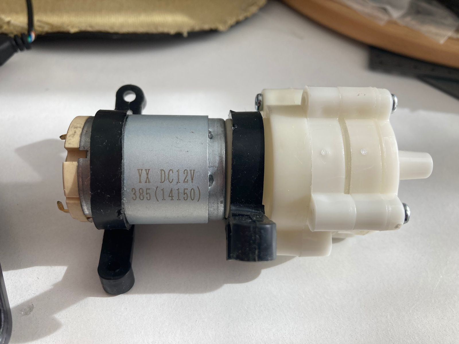 |
Pump Size: 90 x 40 x 35 mm; Ouptup diameter: diameter 6mm, an outer diameter of 9mm; Transit: 1.5 - 2L/min (approx), maximum suction: 2m; Lift: vertical up to 3 meters; Life: up to 2500 H, water temperature: up to 80°C; Weight: 106 g; Working Voltage: DC12V;Working current: 0.5 - 0.7A; Empty load current: 0.18A; Max suction: 2m |
| 6v mini air/vacuum pump | 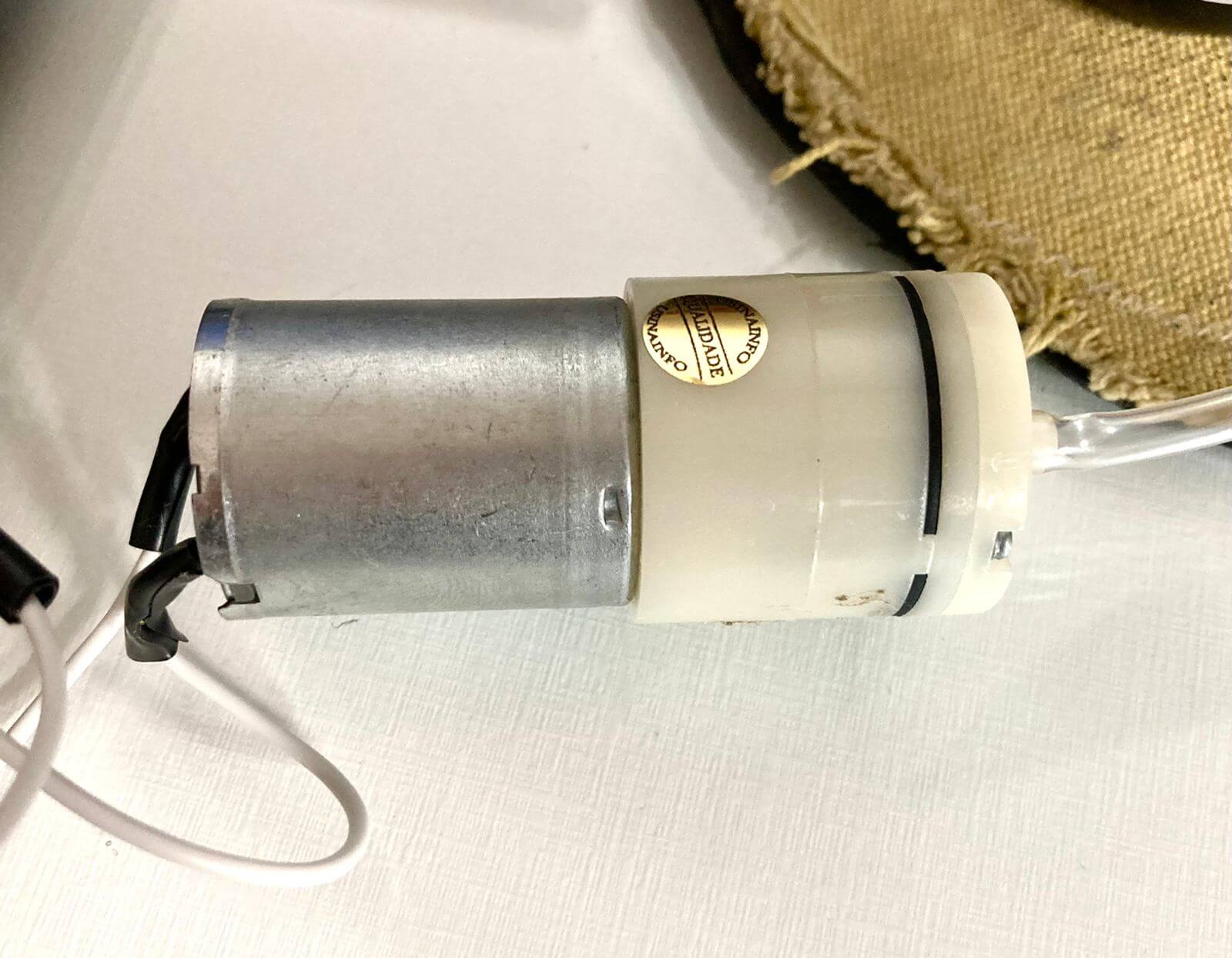 |
Rated voltage: 6V; Rated current: ~290mA; Gas pressure: 86KPa;Flow: 1.8 L/Min; Vacuum: -58Kpa; Inlet and outlet external diameter: 4.2mm; Dimensions (LxD): 65x27mm; Weight: 60g. |
When talking to Adriana, during class time, she told me that to use this pump I probably need to use something to protect my arduino, since it asks for 12V and I can't supply it with the board. I was wondering if this component can't be a transistor? (Emma said that its a transistor, she also said that even though my pump is big, i can try to use it with a circuit driver).
While commenting during the mentorship that I hadn't found any smaller air and vacuum pumps, Iane sent me this option which is half the size and uses half the voltage. I decided to use this one because of the size (it's the second pump in the table above).
Thinking about my final product, I visualize three moments for the resolution of the project:
1) Water that dyes the torso with 4 different colors
For this one, I have a few questions:
- Is it possible to use only one pump to do the work of the 4 dyes?
- Or do I need 4 pumps connected in a parallel scheme (so as not to split the voltage)?
Emma said that it is possible, doing a port, but its better to work with 4 pumps becaus it's easer, and I have few time
2) Torso that contract
- Use air and vacuum pump.
3) Connection of the two previous moments: while dyeing, the torso contracts in time with the heartbeat.
Some doubts:
- Is it possible for a pump to do these two acts at the same time (my pump is air/vacuum/water)?
- How to connect the two parts of the project in arduino?
- How to accelerate the speed of the heartbeat during the act to give the idea of tachycardia?
Emma said that its too complex due the time that I have, and suggested to me to simplify some things and foccus on the air/vacum and if there is time, make the water part mecanized (because its simplier). But she also left me free, respecting in case I don't want to simplify.
changes on my ideia after the mentoring day
I decides to simplify a little... instead using pumbs for the water part, I will do what Anastasia suggested in my MID Term presentation and use the hospitalar bags (which are already manually adjustable). Since, I will need to foccus just in the air/vaccum part and the programming on arduino will be easer.
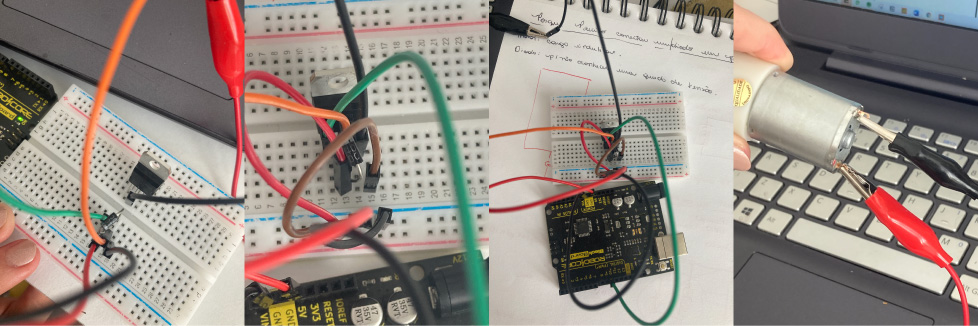
assemblying the circuit
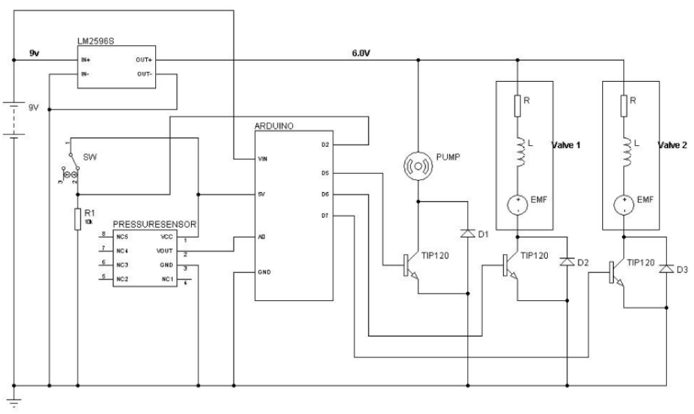
1st assembly based on the soft robot tool kit
In the schematic above, she uses one transistor and one diode for each valve ( 2valves and 1 pump), and one voltage regulator, one pressure sensor, and one switch. I decide to start just with the pump, the voltate regulator and the switch. This first try didn't worked.
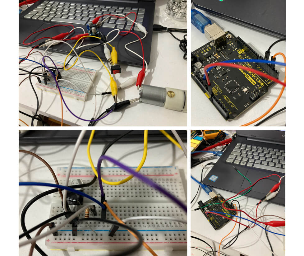
I had to confess that I had difficulties to mount the transistor in parallel with the diodes and valves, for me it was like a puzzle!
As my first try didn't worked, I assembly the hole circuit with 2 valves and 1 pump for test but did not worked eather.
/*first try - Brunna
 */

const int motor= 5; //LED connected to digital pin 5int digital_sensor_pin = D5;   //change the pin, where the sensor is connected?
const int swicht= 2; //LED connected to digital pin 10int digital_sensor_pin = D2;   //change the pin, where the swich is connected?


void setup()

{
pinMode(swicht, INPUT); //sets the digital pin as input
pinMode(motor, OUTPUT); //sets the digital pin as output
}

void loop()
{
digitalWrite(motor,HIGH); //turns the LED on
delay(5000);
digitalWrite(motor,LOW);
delay(30000);
}
testing my pump
I was very lost in this problem, so I decided to test just my pump to see if was working and yes, it was working, but not responding to the programming.. so the problem was me, my code and my assembly of the circuit.
testing my switch
I decided to test my switch with an LED to indicate the operation of the circuit. I mounted the board with the voltage regulator.
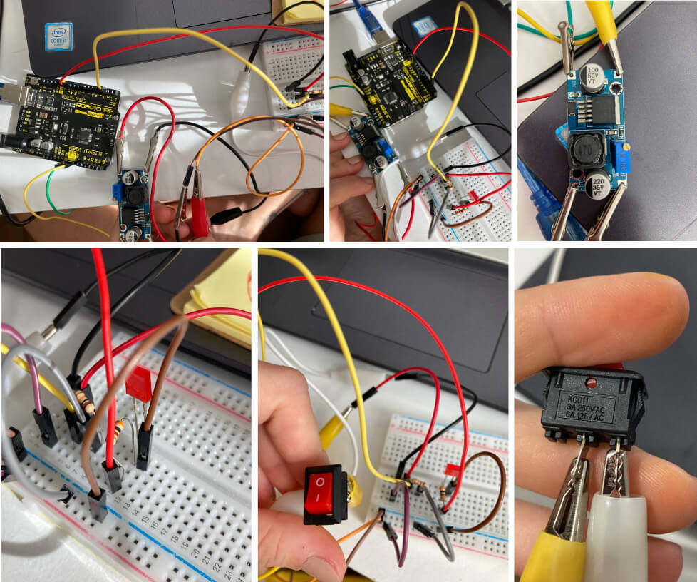
At the first moment it worked, but not as I wish because the LED hadn't turned off, just reduced the light when the switch was pressed.
I tested with 2 different switches and Used the sketch from Robocore (The supplier of my board.)
sketch from Robocore

const int pino_botao = 2; // pin where the switch is connected
const int pino_led = 11; // pin where the LED is connected
int estado_botao = 0; // variable to hold the botton stage

void setup(){
  pinMode(pino_botao, INPUT); // configures the sitch as input
  pinMode(pino_led, OUTPUT); // configures the lED as output
}

void loop(){
  /* the new stage of the switch will be the same of the pin where is connected in Arudino. It can be high (HIGH) when pressed, or low (LOW) */  estado_botao = digitalRead(pino_botao);

  if (estado_botao == HIGH){ // if pressed  (HIGH)
    digitalWrite(pino_led, HIGH); // light the LED from pin 11.
  }
  else{ // if not pressed (LOW)
    digitalWrite(pino_led, LOW); // turn off  the LED from pin 11.
  }
}
ops... burning my arduino
But, with this circuit and code, I burned my board :(.
After a while and my board got too hot, my Arduino IDE stopped showing the port options to select.
When contacting the supplier, he explained to me that I probably damaged my board by pressing the switch and sending the voltage to the board because I didn't adjust the voltage regulator correctly.
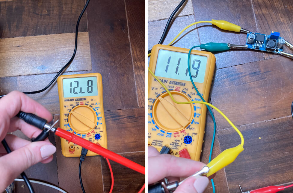
Checking on the multimeter, in fact I did not regulate correctly the voltage regulator.
What an innocence of mine, I really thought that when I put the regulator in the circuit, it already had a specific voltage (6V). The reality is that I was sending almost 12V to the board.
call for help
Right at the beginning of the mentorships Emma commented that this was a difficult circuit and that if I could and had help with it, it would be better. After damaging my Arduino board I decided to call two friends who understand much (much!) more about electronics than I do: Enzo Lopes Amaral and Simão Angel Xavier.
They taught me how to regulate the voltage regulator:
But even after assembling the circuit (the scheme I showed above in this documentation page, with two valves and a pump), it didn't work. We tested various programs/codes. The problem is that when assembling this way, a solenoid valve blocked the air flow and it did not reach the inflatable.
My video recording was scheduled for the next day and it was already delayed because of all the unforeseen not only with the arduino, but the soft robot in general. As I had already rescheduled several times with my friend who was going to do the recording, I decided to simplify the circuit.
So we put only the pump and remove the solenoid valves since it was the part that was giving the problem. The pump was programmed to fill the inflatable in time with the heartbeat and it worked (after a few time trials).
However, we knew that this shape would have a filling limit (after some air pressure was put in, air would start to flow through the inlet hole).
It was already dawn, there were only a few hours left for recording and I still needed to assemble the whole piece, but that's when I had the idea of looking at previous documentation of the soft robotic week in the hope of finding someone who had already assembled the circuit before and had success.
And I found it!!!!!! Thanks to the documentation by Julie Merlino, Vicky Luan and Montserrat Ciges I found some examples of circuits that worked. The difference between them and what I was using as an example is that instead of using 2 solenoid valves plus the pump, they only used 1 valve + pump.
Sketch from Vicky Luan

/*
  Blink

// the setup function runs once when you press reset or power the board
void setup() {
  // initialize digital pin LED_BUILTIN as an output.
  pinMode(5, OUTPUT);
  pinMode(9, OUTPUT);
}

// the loop function runs over and over again forever
void loop() {
  digitalWrite(5, HIGH);
  digitalWrite(9, HIGH); // turn the LED on (HIGH is the voltage level)
  delay(1000);                       // wait for a second
  digitalWrite(5, LOW);
  digitalWrite(9, LOW);// turn the LED off by making the voltage LOW
  delay(1000);                       // wait for a second
}
Montserrat Ciges documentation
sketh from Montserrat Ciges

int solenoidPin = 4;    //This is the output pin on the Arduino we are using

void setup() {
  // put your setup code here, to run once:
  pinMode(solenoidPin, OUTPUT);           //Sets the pin as an output
}

void loop() {
  // put your main code here, to run repeatedly:
  digitalWrite(solenoidPin, HIGH);    //Switch Solenoid ON
  delay(2000);                      //Wait 1 Second
  digitalWrite(solenoidPin, LOW);     //Switch Solenoid OFF
  delay(2000);                      //Wait 1 Second
  }
final circuit and final code
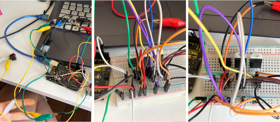
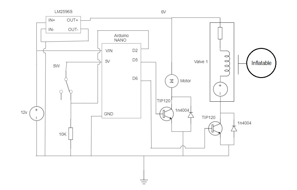
So, we combined these provided examples with the previous one we were using from Adriana to build our circuit with a 12v source (so it could be plugged into the outlet), a voltage regulator (correctly regulated to 6v), and a switch to turn it on.

We assembled and solder the final circuit in a Universal PCI board.
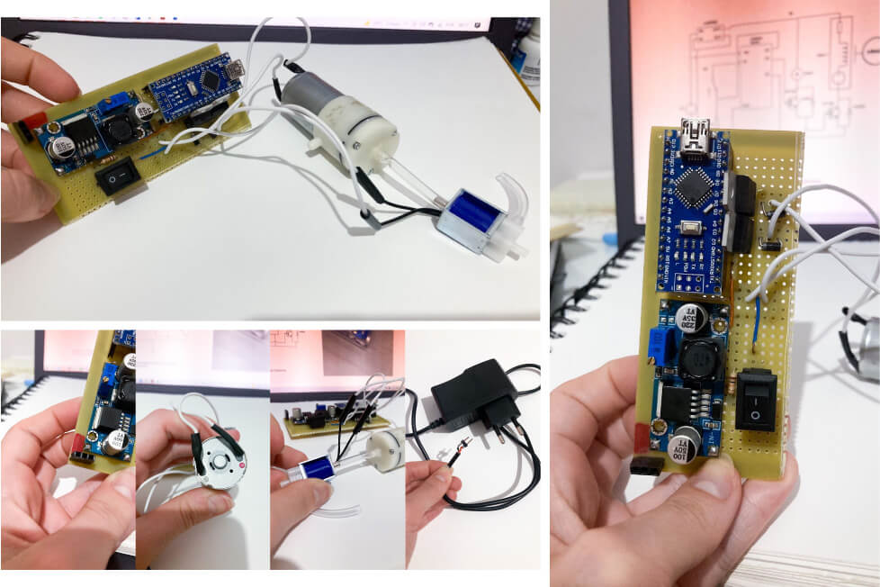
We need to cut the end of the power supply and solder male jumpers to enter the board correctly and cleanly. We also indicate the positive side with red enamel on the end plate.
The final circuit and the schematics:
Here's the video of our final test (with the input channel not yet sealed).
Code:
const int pino_botao = 2;
const int pino_motor = 5;
const int pino_valvula1 = 6;
const int batida = 400;
const int espera = 500;
const int parada = 20;
int liga = 1;
int estado = 0;
int botao = 0;

void setup() {

   pinMode(pino_botao, INPUT); // pin in
   pinMode(pino_motor, OUTPUT); // pin out
   pinMode(pino_valvula1, OUTPUT); // pump out

}

void loop() {
  botao = digitalRead(pino_botao);

  if (botao == HIGH) {

     if(estado == 0)
     {
       digitalWrite(pino_motor,HIGH); // make sure pump is on
       digitalWrite(pino_valvula1,LOW);
       delay(batida);
       estado = 1;

     }
 else if (estado == 1)
     {
       digitalWrite(pino_motor,LOW); // pump is off
       digitalWrite(pino_valvula1,HIGH);

       estado = 2;
       delay(parada);
     }
     else if (estado == 2)
     {
       digitalWrite(pino_motor,HIGH);// make sure pump is on
       digitalWrite(pino_valvula1,LOW);

       estado = 3;
       delay(batida);
     }
     else
     {
       digitalWrite(pino_motor,LOW); // pump is off
       digitalWrite(pino_valvula1,LOW);

           estado = 0;
       delay(espera);
     }
    }

  else if (botao == LOW)
  {
      digitalWrite(pino_motor,LOW); // pump is off
      digitalWrite(pino_valvula1,HIGH);
  }
}
credits and special thanks again to Credits and Special Thanks toEnzo Lopes Amaral and Simão Angel Xavier!
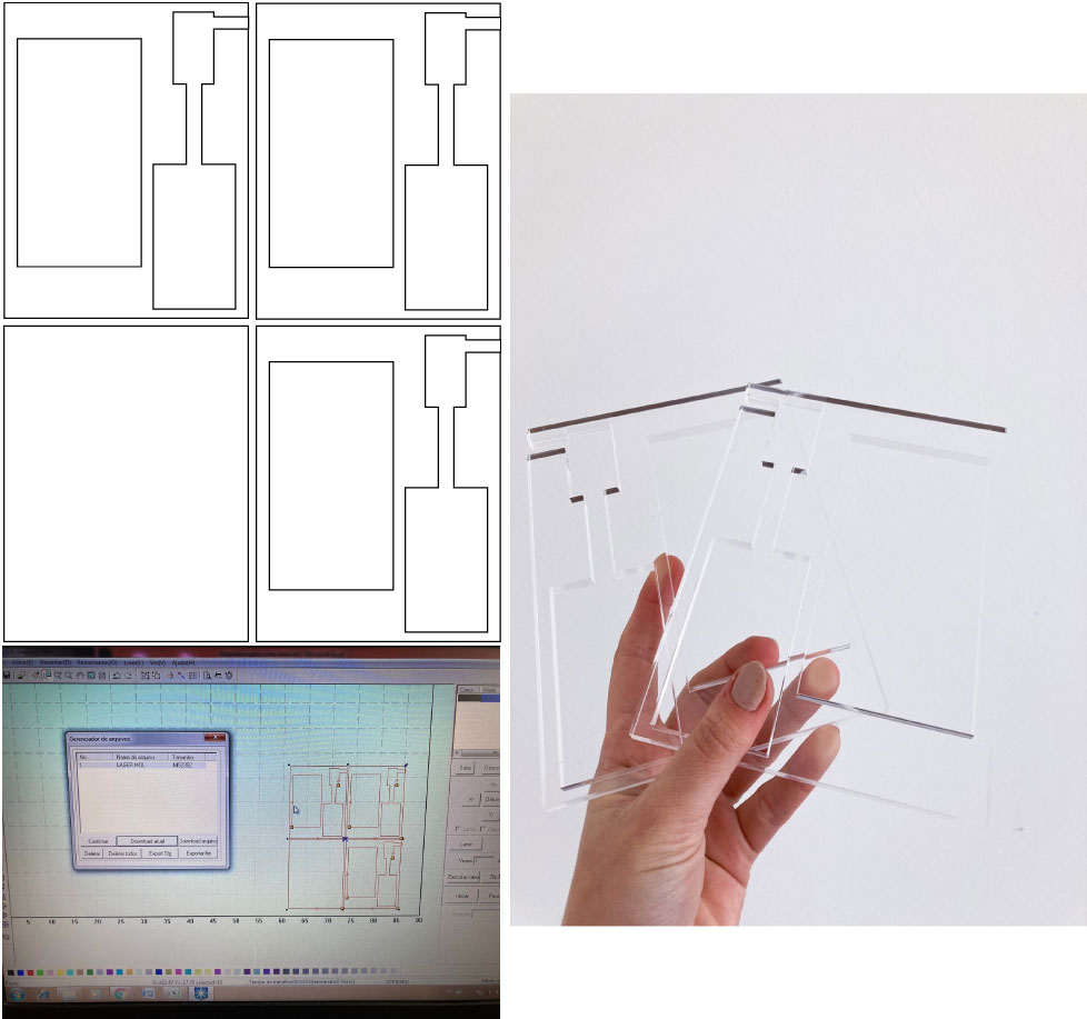
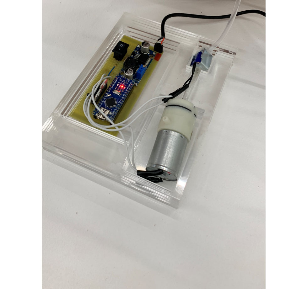
lasercuted case for my circuit
To keep my motor from moving while filming the installation, I laser cut a case out of 6mm acrylic. I glued the parts.
Laser cutting the case for my final circuit from Brunna Ramos on Vimeo.
Final case:
Arquives can be downloaded here.
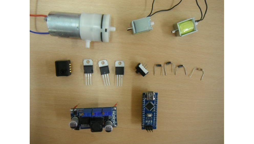
list of materials (components and tools) for the assembly of this circuit:
Componets and tools for assembly the main circuit:
if you need, case:
you can assembly this board with another material of your preference!
have fun and take care :)
SCAFFOLD
This idea of working on top of the shape of a torso came about during Textile Scaffold week, at the time, I made an industrial eva mold on the CNC router using industrial EVA rubber, and modeled a cotton textile waste paper on top with an adaptation of a recipe by Angela.
I would like to use this same material for my final project but the paper was very fragile, so it certainly couldn't stand to be suspended and receive the weight of water while it was dyed.

documentation of this assignment here. download the torso here
biomaterial previous thinking and research
At first, I thought of combining this material with some biomaterial on its backside to make it stronger. However, I need to know if the biomaterial will not melt as the water passes through to dye the material.
So, my first ideia its to make the paper, and then, demould it on a flat and wet bioplastic surface (leaving the tube for the passage of water between the materials).
But, when talking to Algela she said that it's better demould the paper still wet in the bioplastic.
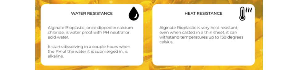
Something that was causing me several doubts was regarding the composition of the bioplastic chosen for the base of the material. Since gelatin and agar are very sensitive to heat and water. This can be seen in this table:
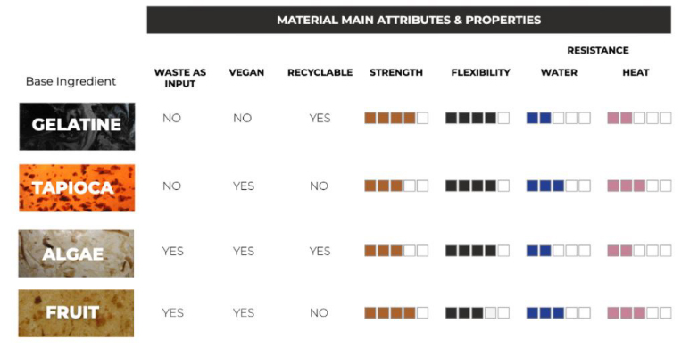 image from Beatriz Sandini final project documentation's
This image made me think... if I use tapioca? But thinking about water, alginate it's the better solution as cecilia showed in Biomaterials Class:
However, I had some experience with the material during week 6 of Fabricademy and saw that the material shrinks a lot when dry, even mixed with the shredded textile residue (although it shrinks a little less that way).
Taking a look at the documentation of the final project by Loes Bogers, I saw this composite made with agar that has very interesting properties and makes the fabric look like paper, so I thought: what if I do the same, but instead of using paper I Do I use the alginate bioplastic sheet recipe?
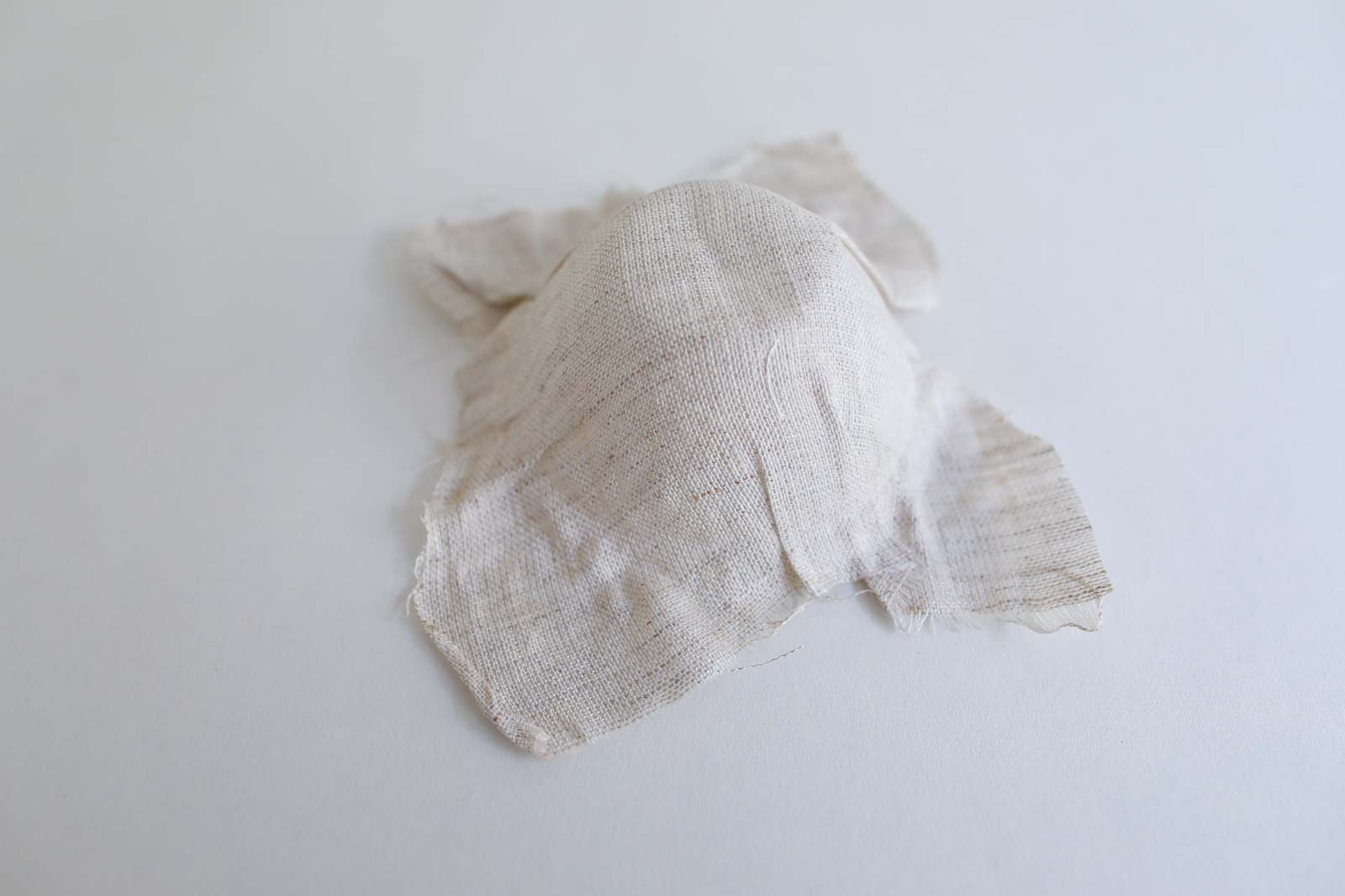 image from Loes Bogers final project documentation
So, I testest fabric composite + alginate on a three-dimensional surface (torso), to see if the fabric would help the alginate to shrink less and perhaps consider a possibility of applying it to a future textile waste paper.
tests with alginate composite
For these tests I did 1/2 recipe:
| recipe | alginate | water | glycerin | Calcium Chloride Solution |
|---|---|---|---|---|
| alginate bioplastic sheet | 6 g | 200 ml | 20 g | 100 ml water + 10g calcium chloride hydrate |
I made 2 tests, one using an very light cotton fabric, and another using a slightly more structured linen fabric.
Steps:
- mix the ingredients (alginate, water and glycerin), I used a hand mixer to help;
- wait for the bubbles leave;
- Meanwhile, accent the fabric in the desired mold (in my case, the torso);
- When the bubbles have come out, pour the material and mold (I used my hands but you can use a wide brush).
- Spray the calcium chloride solution on top of the composite;
- Spray water to remove excess solution;
- Let it dry.
In fact, as in the Loes recipe with Agar, the alginate shrinks much less when mixed in a composite fabric, mainly it is thicker and closed, as was the case with linen (the thin cotton fabric contracted a little). It is important to note that I chose a recipe that shrinks less (the sheet) to make the composite, the bioplastic itself (thicker recipe) shrinks more.
However, none of the solutions pleased me as I would have liked... as they were not so rigid.
When commenting on my tests and my doubts with Angela, she suggested that I work only with conventional Silicone, because in addition to making the structure more rigid and allowing it to be wet, a soft robotic was going to be attached to the back of my model (which should be inflated) and similar materials are easier to glue. Due to time and the complexity of joining the parts, a material that was sure to work was what we needed at this moment.
tests with shredded textile waste paper + silicone
preparing my shredded textile waste for recieve natural inks
As the textile will had receive natural dyes, I decided to prepare it with scouring, tannin and mordants to fix the colours. That's because even though the installation is recorded and for a finite time, I want to keep the dyed torso for myself.
- The first thing we must do is cut the residue even more, so that it is very small;
- Then, I made the scouring, tannin and mordant steps:
| scouring | tannin | mordant |
|---|---|---|
| Sodium Carbonate (15% WOF) | Pata de Vaca Leafs *Bauhinia fosficata 15% WOF | Alum 15% WOF |
I diluted each of them in 1.5 L of water and boiled (without bubbling) for approximately 40 minutes.
paper making
With the textile waste prepared, I started the paper making.
For these tests I did 1/2 recipe that I adapted from Angela's recipe to work with textile waste (same that I made during week 9).
| recipe | shredded textile waste | water | CMC solution |
|---|---|---|---|
| shredded textile waste paper | 50 g | 5 L | half of soup spoon CMC in 500 ml water, we use just 50 ml of the solution but now I'm using it all |
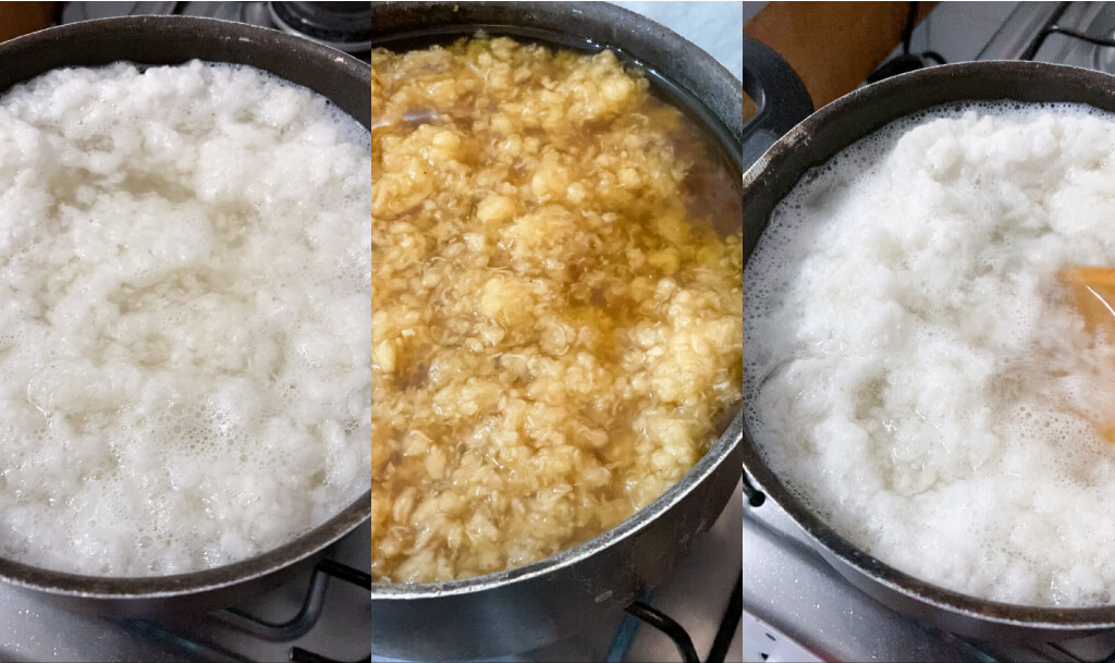
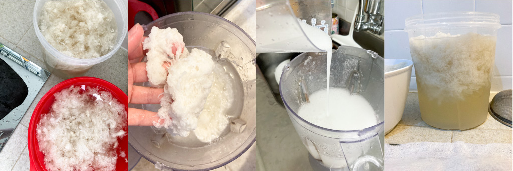
- We pour the shredded textile in 5 liters of water and hit the blender in small amounts;
- When the textile is all blended, we add the CMC solution to the mixture and let it become heterogeneous. All cotton wool must go up. This time I added all the solution because I wanted my paper stronger;
- We put a thin cotton fabric or other material in our mold so that the paper can be removed later, but this time I made a little change in the process: I made my own mold for making papper and decided to combine paper + silicone in a tridimensional mold after with the paper alredy dryed.
mold for making paper
I cut a large flat sieve on the laser cutting machine to make sure my paper was very straight and rigid:
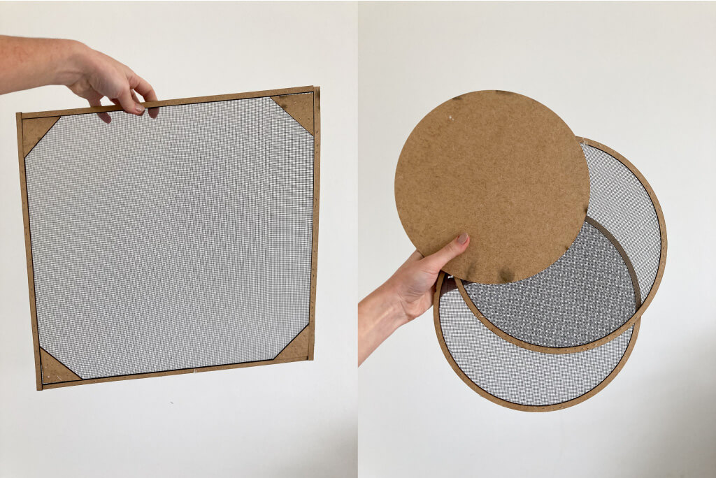 molds here, cutted in a 3mm mdf
I made two molds: a round one (to remove the paper directly from the bucket where the water was) and a square one, I realized after the tests it would be better to first remove it with the circular sieve from the bucket and then transfer it to the larger sieve.
- With the help of the circuar sieve, we remove thin layers of the part of fabric that rose in the water and put it in the mold;
- When it's ready, just let it dry.
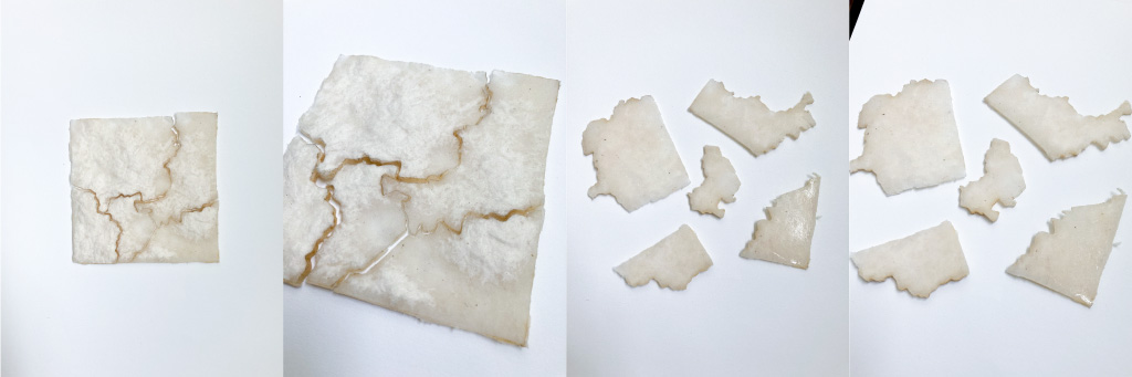
tests
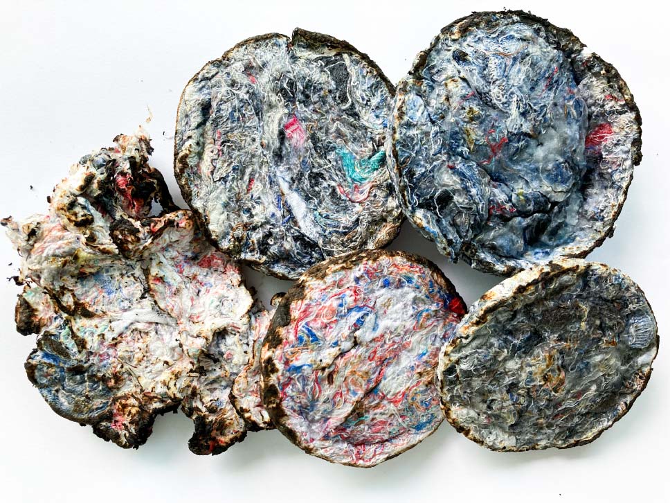
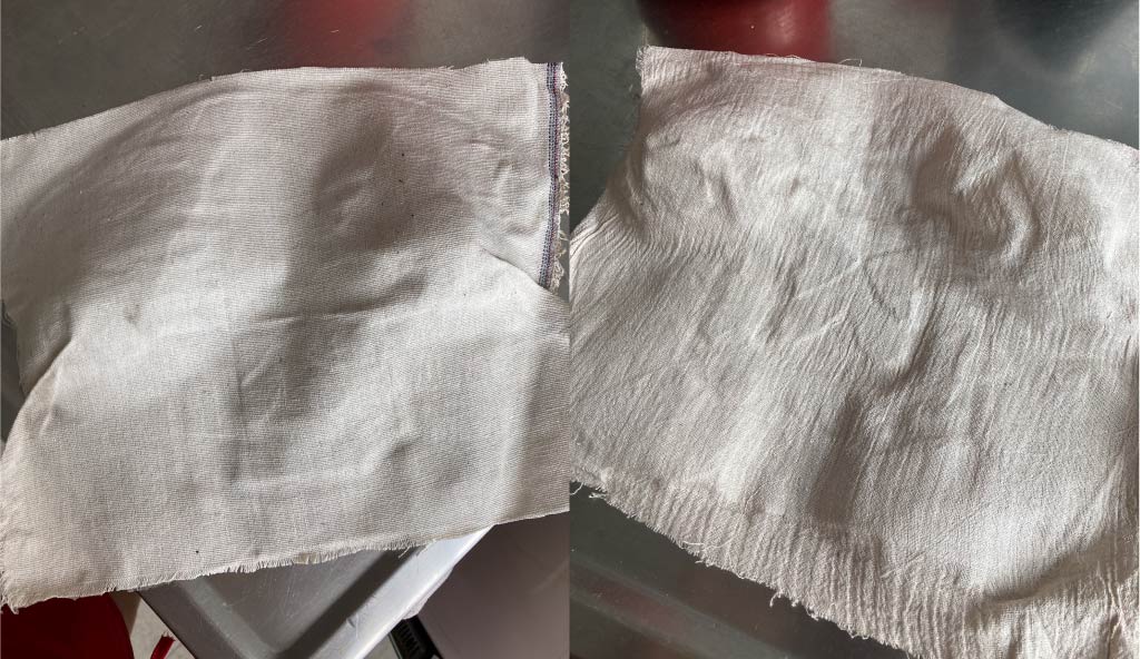
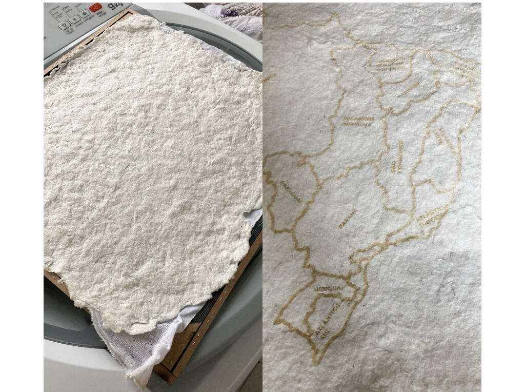
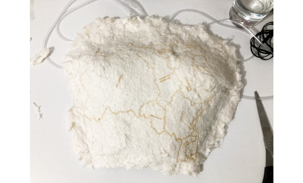
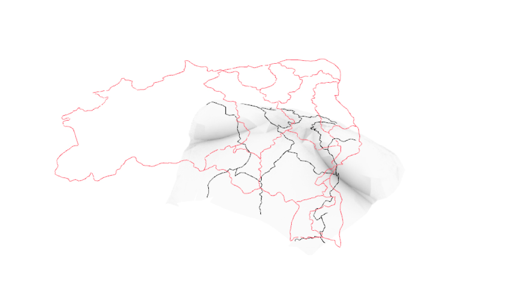
My first test was to see how this paper would react to laser cutting, as I intended to laser cut modules to make the 12 Brazilian hydrographic regions on the torso. To my surprise, this paper looks very nice with the laser cut.
Then, I tested putting the cut pieces in an uncured silicone mixture and waiting for the curing time (24h) to see how these materials would react together and also, what the aspects of the modules would look like together.
I didn't like this result, as the paper absorbs all the wet silicone and doesn't have a good finish and I didn't like the results of the modules together either.
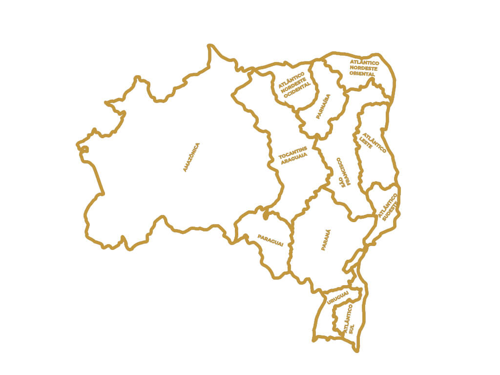
The modules were made randomly from the vectorization of a map of the Brazilian hydrographic regions, I intended to do parametric modeling after but I gave up on the idea, explanation below.
I took advantage of the laser cutting machine to also test the engraving on this material. The result surprised me a lot and gave me an idea, instead of transposing the Brazilian hydrographic regions into modules on the torso, recording them in the material, this would be a simpler and more aesthetically beautiful process. It's a more interesting solution too since when the recording is wet it disappear, and a simplified one (something that I was needing due the time):
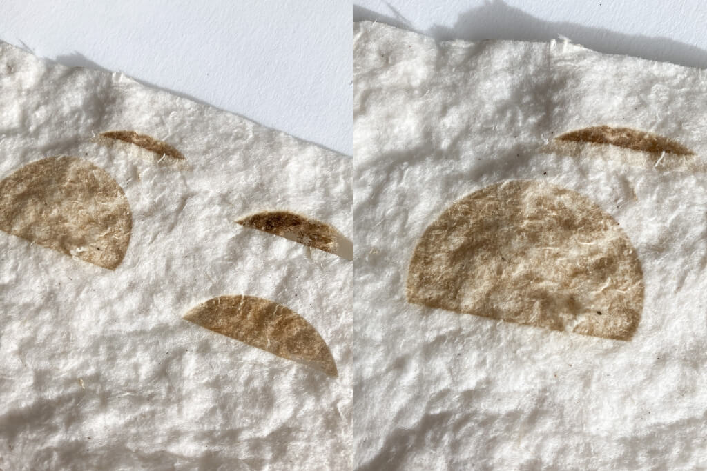
As the paper absorbs the silicone when wet, I needed to understand the exact moment to place the paper on top of the silicone. I tested making the junction with the pre-curing time and the half-curing time.
With the curing time in half, the silicone was already very dry and the paper didn't adhere well, the pre-curing time was the best result (when the silicone still sticks to the finger, but it doesn't get wet, approximately 2 hours latter).
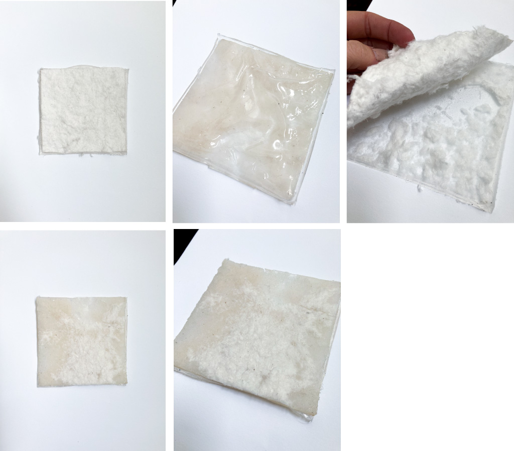
I also tested how the tube + paper + silicone junction would be, and how the ink flow on the paper would be. For this, I glued the tube to the silicone with the silicone itself, and after pre-curing I put the paper. It worked.
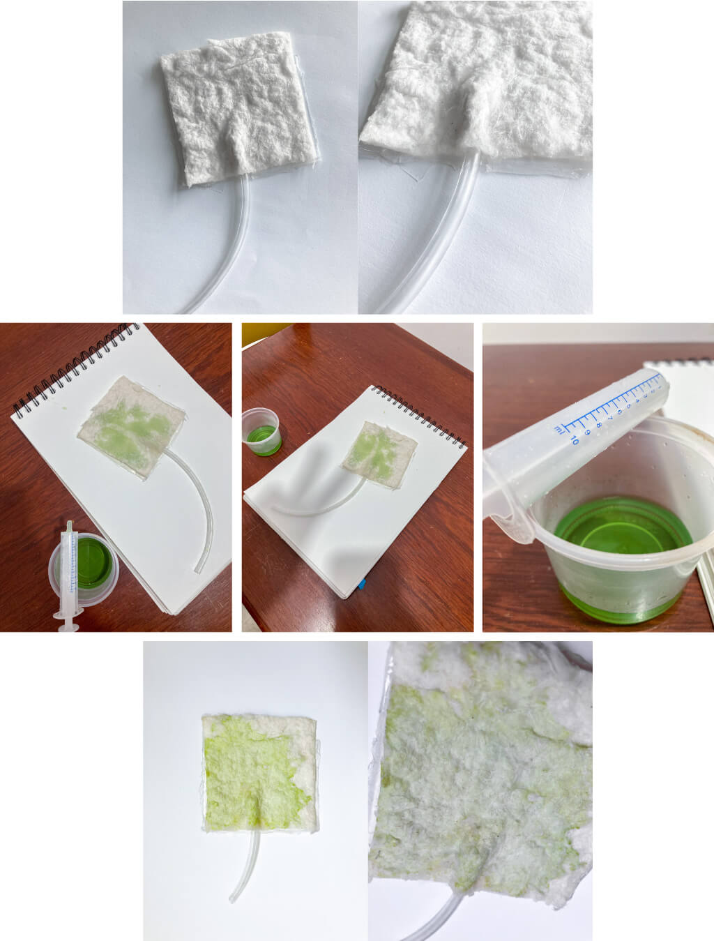
We have to be very careful not to cover the hole in the tube with silicone, otherwise the paint will not pass!.
final assembly
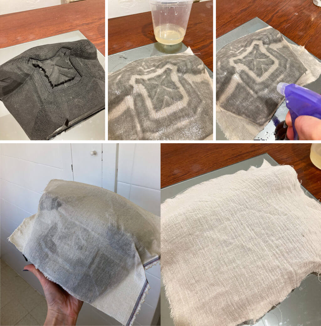
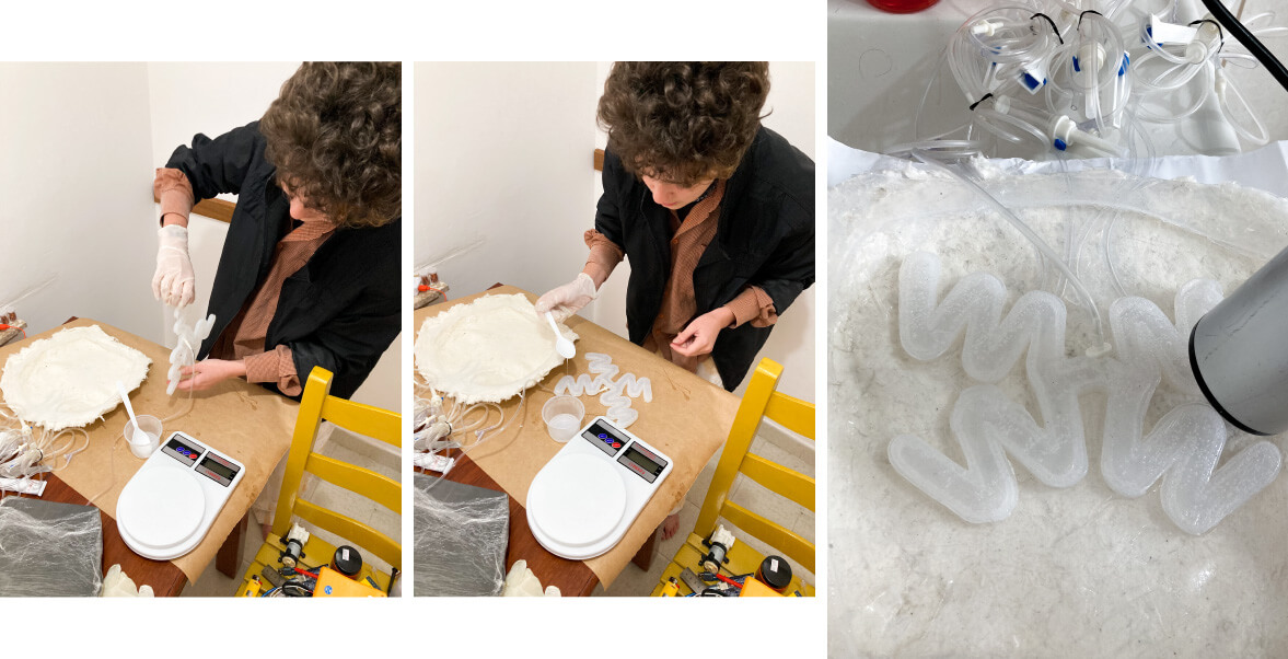
For the final assembly I made a large paper (the size of my mold) and then engraving on the laser machine the vectors.
vectors here
Then, I covered my mold with plastic film (as it had a hole due to a machine error at week 9), and applied silicone (I did about 3 layers) and tubes (4).
When the silicone was already pre curate, I put the paper above it, pressing very well to guarantee that glued well.
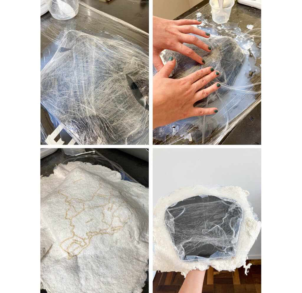
I put the dry paper on, since my tests testing sticking the wet paper to the silicone didn't work very well.
Finally, I removed the leftovers with my hands (carefully) to get a more rustic appearance (when necessary, I softened the paper a little with water to soften it).
Now, my torso is almost ready!
BIOINKS
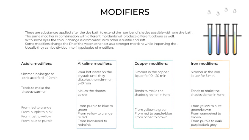
My first idea was to make four recipes: brown, blue, green and bring some modifier to the mix and change those three during installation.
I remember Cecilia commenting during BioChromes week that hibiscus, or the copper modifier could bring blue to the recipe. I decided to test hibiscus because it is more affordable and doesn't have as much health risk as copper (since I did the whole process at home and not in a biolab).


Cecilia's class - BioChromes week
To make the hibiscus turn in to a blue tone, we use sodium carbonate and ethanol (I used just the first one cause I liked the result).
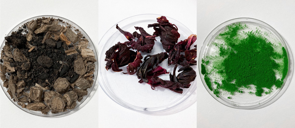
To bring the brown and the green ink, I use clay + Aristolochia brasiliensis and matcha. In the brown I also put some Iron modifier to make it more rusty.
recipes
During the testing process, the hibiscus red gave me an idea that was previously unplanned: using it as blood, to represent the death behind the whole water issue. So I used the hibiscus twice: pure and well concentrated, and a little more diluted with sodium carbonate, so they would turn blue anyway when in contact with the torso.
| image | ingredient | quantity | modifier |
|---|---|---|---|
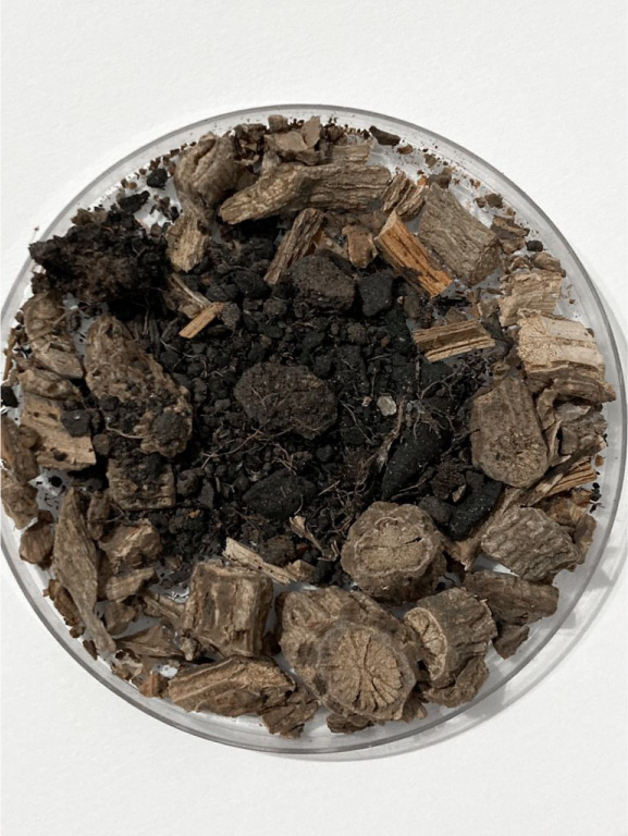 |
CLAY + Aristolochia brasiliensis | some spoons in 500 ml H2O boiled for 40 minutes | 70g Iron modifier |
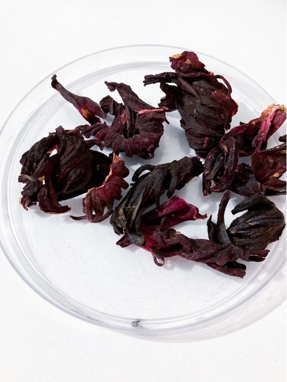 |
Hibiscus | 30g of dyred flowers in 500 ml H2O boiled for 40 minutes | - |
|
Hibiscus | 30g of dyred flowers in 1L H2O boiled for 40 minutes | 1 soup spoon of Sodium Carbonate |
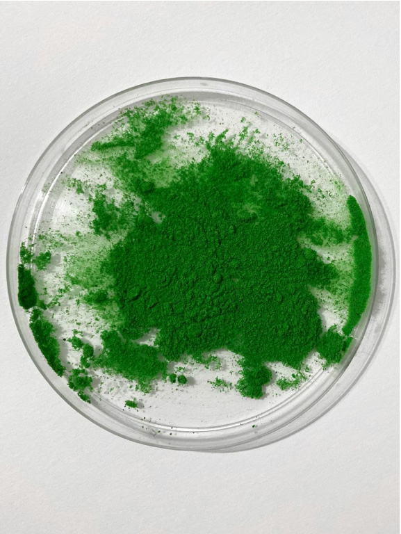 |
Matcha | one soup spoon in 500 ml H2O (hot water) | - |
Some color and ph interaction tests:
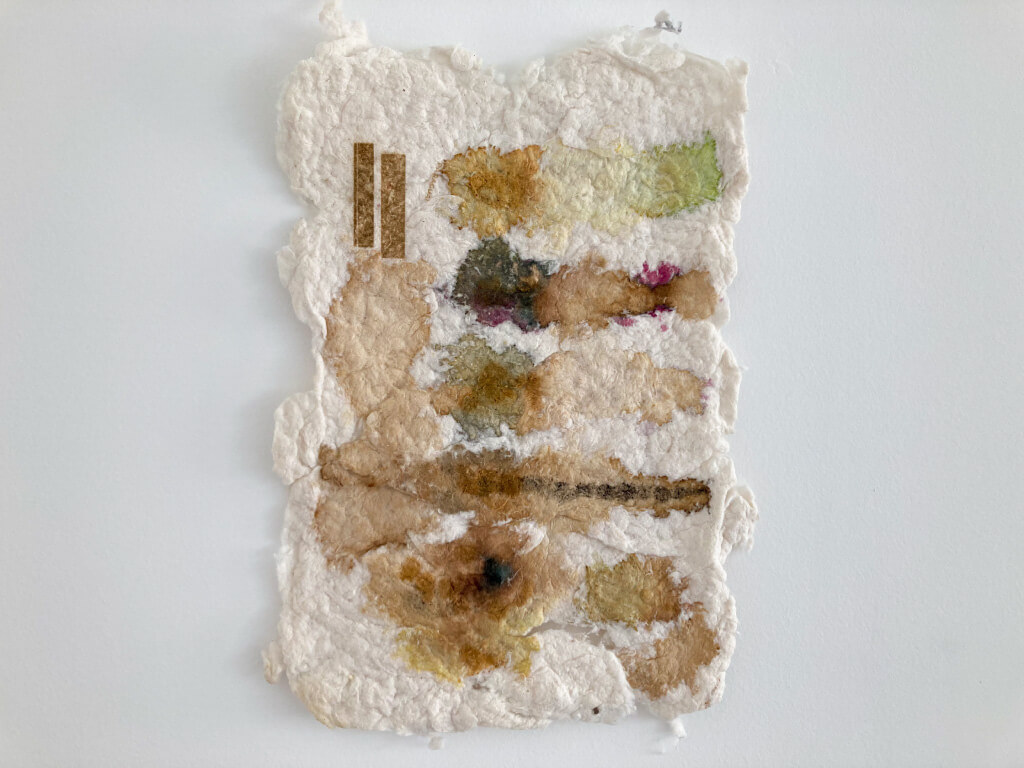
On the right side of the paper, the four lines from top to bottom: matcha, hibiscus, hibiscus with sodium carbonate, and clay. Left of the lines: interactions with iron, in the center: interactions with sodium carbonate.
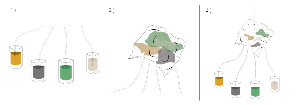
assembling the hospitalar bags
To transfer the inks to hospital bags, I first had to empty the content of all with the help of a tool that in Brazil we call "equipo".
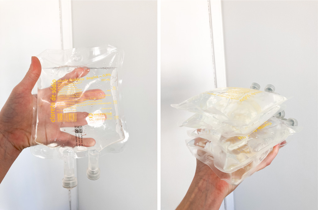
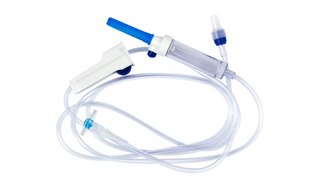
After, with the help of the equipo and and syringe, I added the collours to the bags.
The equipo will make the junction of the torso with the hospital bags and for that we have to guarantee that there is no air entry in the process, otherwise the paint will not come out through the tube (I learned the worst way possible! Check the video making documentation).
This class shows exactly how to do (in Portuguese):
When the thread is on top of the device, the liquid flow is closed, and when it is on the bottom, it is open!
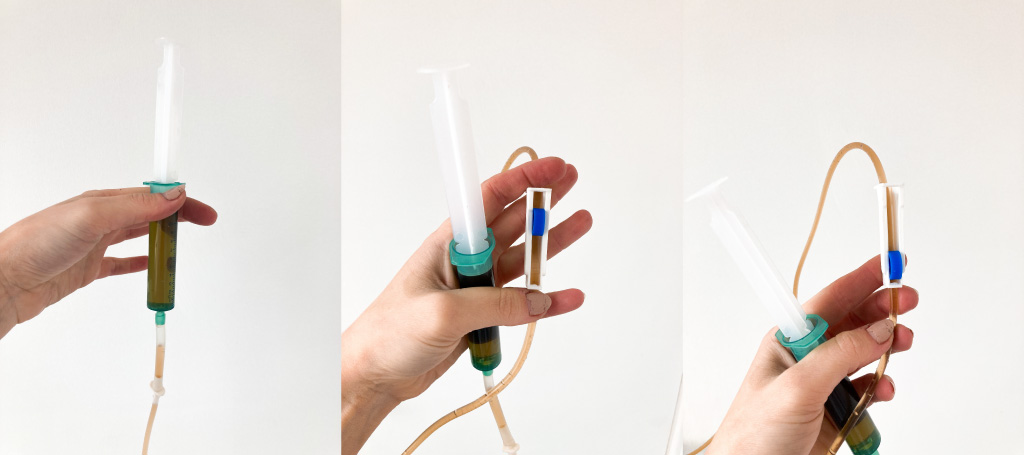
final bag:
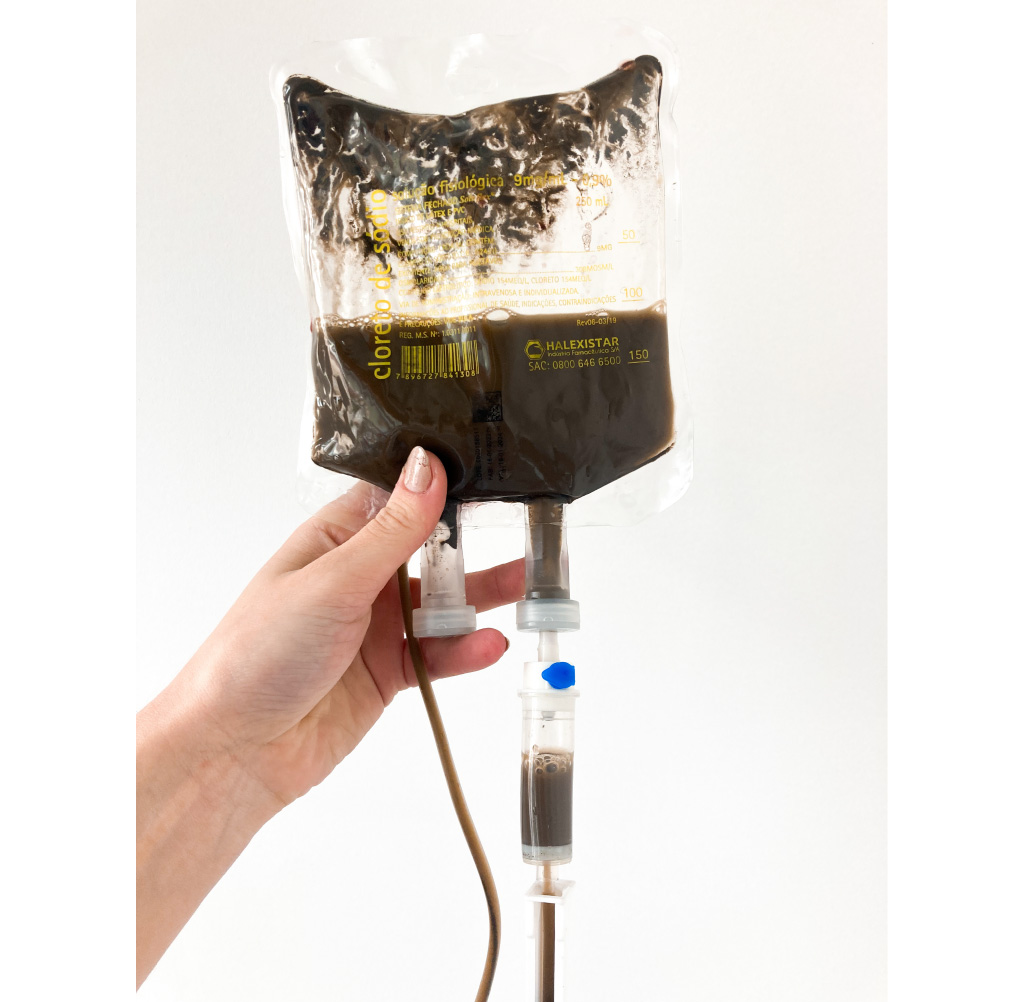 I made the same process with the 4
JOIN PARTS AND AIR ISOLATION
For joining the parts, I used the same silicone from the previous processes to glue the back of the torso together with the back of the soft robotic. With the help of a hair dryer I dried it.
tests - silicone glues
With the soft robotic glued, it was time to isolate the air flow, for that I had to test several glues.
At first, I was careful not to use certain components due to the silicone manufacturer's specifications, as these could damage it. So I tested the joins 1 to 4 of the table.
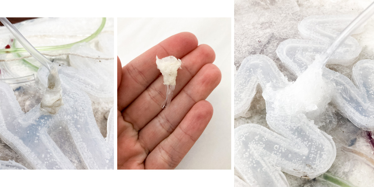
The silicone I was already using seemed like the best way to insulate the air, but the material didn't stick very well to the tube that was attached to the soft robotic, so after a while of airflow, it came off. It was a problem because I discovered it during the recording of the video, and I had to reschedule another day of video so I could try to isolate it again (problem better explained in the video making tab). I tested all glues from 1 to 4 until recording the video directly in soft robotic and it ended up harming the finish of the model, finally, the insulation part ended up coming out in my hand.
Another thing I noticed was that due to the fact that the torso was suspended, the insulating channel should allow the air tube to not bend, so that the air passage would not be hampered.
| image | name and link | it works? | |
|---|---|---|---|
| 1 | |
Silicone | at first yes, but it can't handle the air pressure, after a while of air passage it starts to leak |
| 2 | 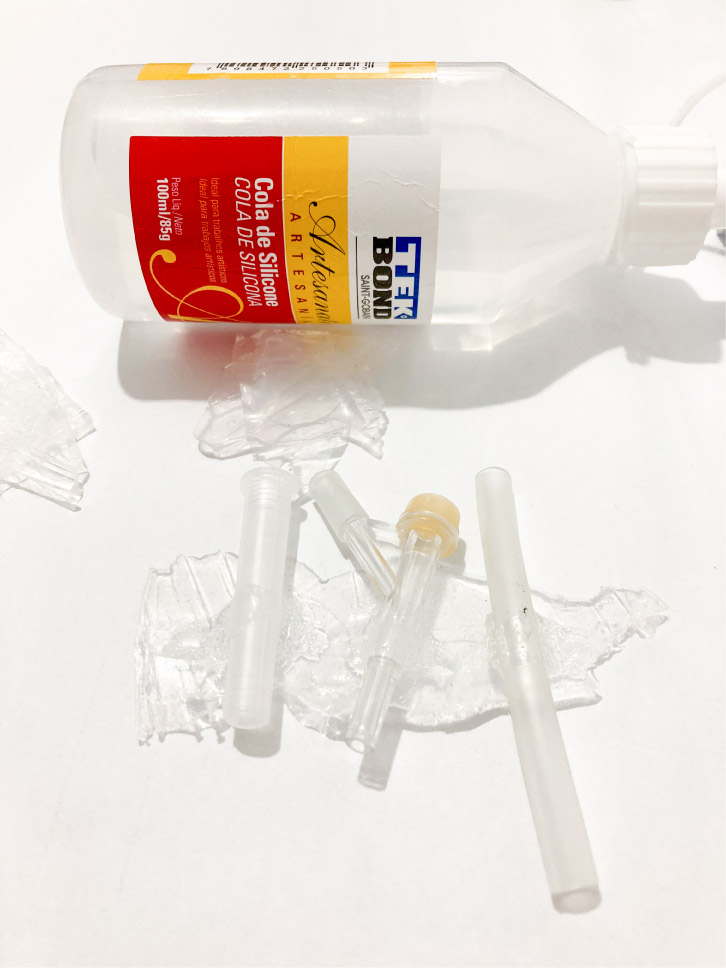 |
Craft Silicone glue | No |
| 3 | 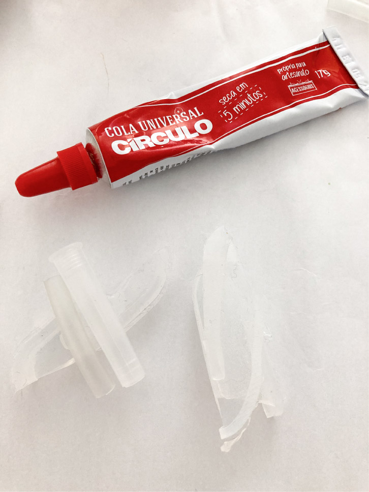 |
Universal glue | No |
| 4 | 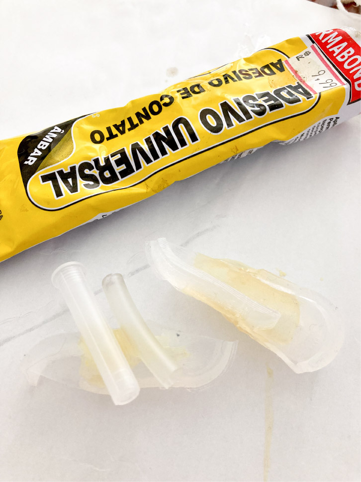 |
Universal contact stiker | no |
| 5 | 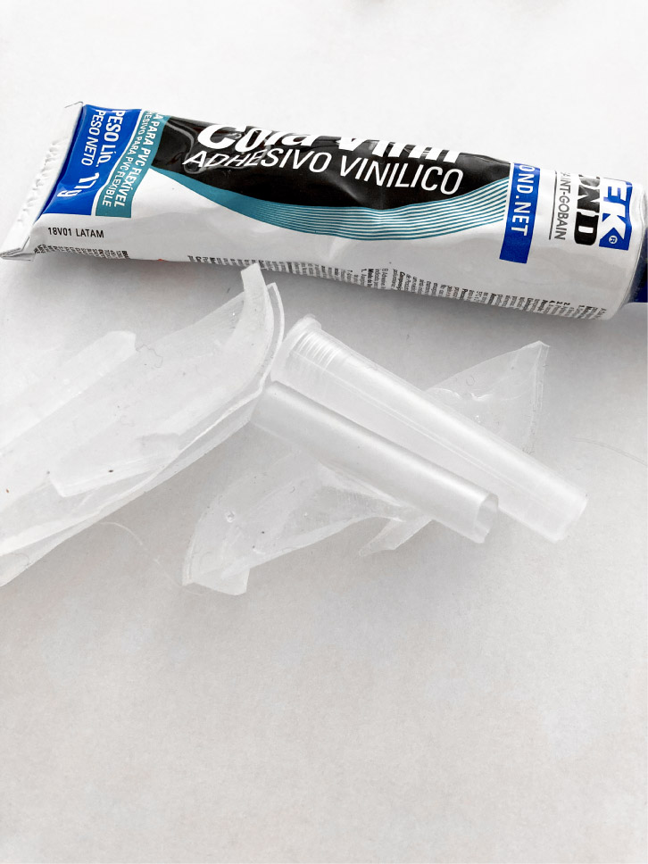 |
Vinyl glue | no |
| 6 | 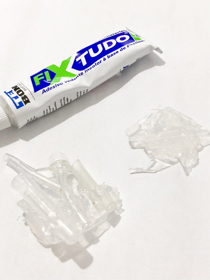 |
Fixtudo Sealant Adhesive | no |
| 7 | 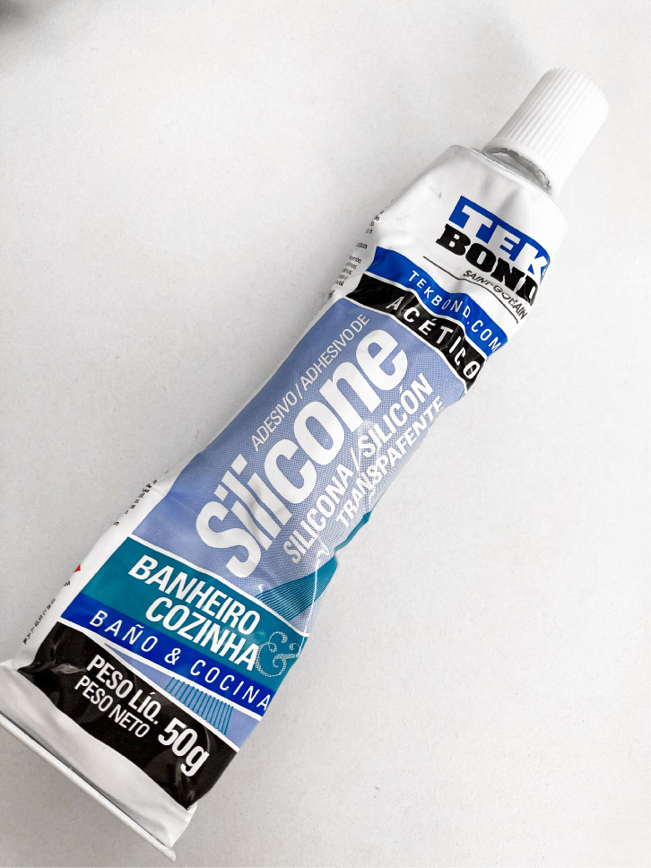 |
acetic silicone | yes! |
As I only had one more day to record the video and the time limit was running out, I decided to test the glues with components not indicated by the manufacturer (ie glues with epoxy), but they didn't work either. I was about to give up when I watched a youtube video where they use acetic silicone (usually used to seal bathrooms, kitchens and wet areas, in other materials that are not silicone based like marble or glass), I decided to test and it worked!
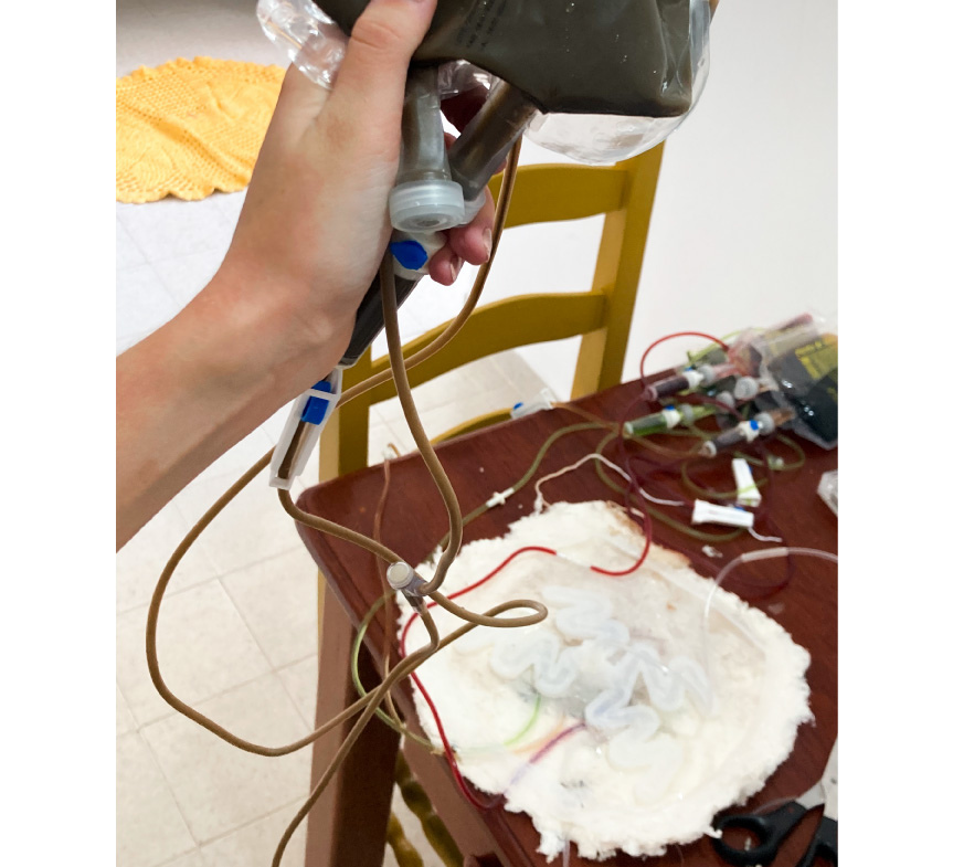
It is a strong chemical with a strong smell, and is difficult to finish. Due to my problem on the first day of recording I decided to make my torso and my insulation as thick and strong as possible, even though it would end up with an ugly finish, as I couldn't take the risk of going wrong on my last day of recording. I also tried to make it reinforced to the point that the tube would not bend when the torso was suspended.
Finaly, I concected the torso with the hospitalar bags and I was ready to start my filmed installation.
The final assembly of the entire installation it on the video making documentation.
CHANGES ON THE WAY AND SIMPLIFICATIONS OF THE PROCESS
As already explained during this documentation (and suggested by the jury during the mid term presentation), the process was simplified due to the complexity of the project and the short execution time (about one month). Here a summary:
-
Choose to use conventional silicone instead of working with a biomaterial. However, I wonder if it is possible to make a flexible, water-resistant biomaterial to be used in place of conventional silicone?;
-
Giving up parametric modeling to cut the vectors of watersheds and choosing to record them.
I was planning to do the modules through computational couture, cutting the modules with the laser in the still flat biomaterial and molding through the scaffold. For the parameterization of the soft robotic vector on the torso, I rewatched classes 5 and 6 of the Computational Couture week (a lot of times) and tried to do the exercises that I hadn't had time to do before. However, I was not very successful in my result:
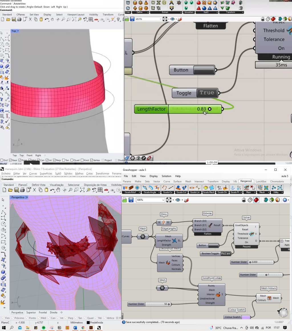
Also, I just realized during the experiments with grasshopper, that this process was not so necessary and it was just a detail, so I decided to discontinue this activity.
-
Work on the circuit with just one valve and one pump and no pressure sensor.
-
Valves for the release of manually controlled paints (hospital bags).
-
I was planning to do the 3D modeling with Solid Works software, but it was something that didn't give me time because it would require learning a new program. However, I still want to test it at an opportune time.
All files of the project here.
REFERENCES
soft robotics
Under my skin by Ayse Esin Durmaz
Serena: a wearable to combat anxiety and induce calm by Wei Cheung
Bodymimicry by Montserrat Ciges
Actuators by Soft Robotic Toolkit
Fabricademy Soft Robotics Week
Silicone Rubber to by in Brazil
eletronics and programming
How to control the actuator by Adriana Cabrera
L298N Motor Driver – Arduino Interface, How It Works, Codes, Schematics
Low cost Electro-pneumatic circuit for Soft Robots- these one inspired my final circuit
Montserrat Ciges documentation
scaffold and biomaterials
Ephemeral Fashion Lab by Beatriz Sandini
Fabricademy week 6 biofabricating materials
Fabricadmey week 9 Textile as Scaffold
My assignment of biofabricating week
bioinks
extras
Acetic Silicone available in Brazil
How to fix silicon rubber mold - in portugese
Fabricademy Computational Couture week