05 e textiles
19 - 26th October 2021
5. E-textiles
I'm excited to see what I can achieve this week because electronics is an entirely new territory for me. The beginnings of computer coding came from weaving and so it's not so detached from craft and fashion at all..
thoughts and inspiration
Electronics is about making actions and processes; inputs and the calculations you make for outputs. So, it's similar to the nature of craft and weaving because you might calculate or plan your techniques for specific results.
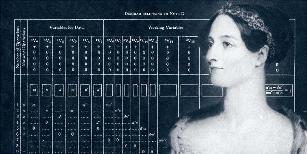
In fact one of the first designed computers was the Analytical Engine. It was inspired by the jacquard loom - the first to store its own information by punching holes in cards to remember the processes. The Analytical Engine was imagined as a textile mill by Charles Babbage and his assistant Ada Lovelace. Ada's work and research on this project were vital in creating the Automatic Sequence Controlled Calculator - the first operating machine that could execute long computations automatically.
I found these coding/weaving workshops and some more info in this article too
EJTECH are a really cool collective redefining sensory experiences with texiles and sound: hyperphysical interfaces, programmable matter, and augmented fabrics as media. I found their work really inspiring.

Also this article from earlier this year has some really innovative references.
electricity
First I need to clarify the basics:
- electricity flows in an anticlockwise direction/negative to positive
- voltage
- electrical pressure between 2 points
- difference in charge (more voltage/more force/pressure)
- measured in AC (alternate current) or DC (direct current, travelling one way)
- voltage is not consumption but force
-
resistance = amount of material resisting the flow of a current
- relative force
- resistors define the flow of electrons*
- position of resistor does not matter
- resistor's purpose is to impede current flow and reduce voltage
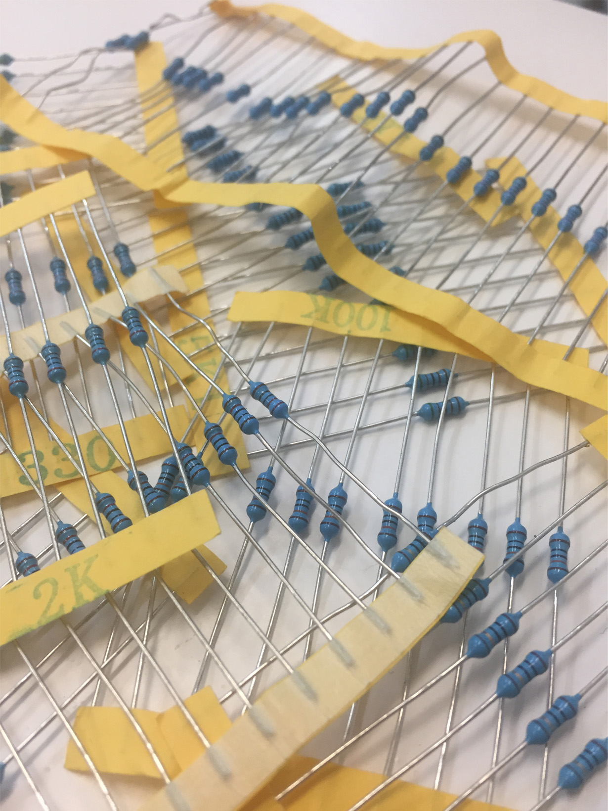
i find the resistors really pretty like some ancient egyptian jewellery
-
current
- amount of electrons allowed to pass/speed
- movements of electrons is measured by amp
- Ω [OHMs]
- V(voltage) = I(current) x R(resistance) = IR
- high Ω = more electrons
- resistance is measured on the multi-meter as Ω 1kΩ = 1000Ω / 1ohm = 0.001kΩ
- load = consuming component (eg LED/motor/)
- piezoresistive effect
- a change in electrical resistance of a semiconductor/metal when strain is applied
- dielectric
+an electrical insulator that can be polarised by an applied electric field +(an electrical field = the physical field that surrounds electrically-charged particles)
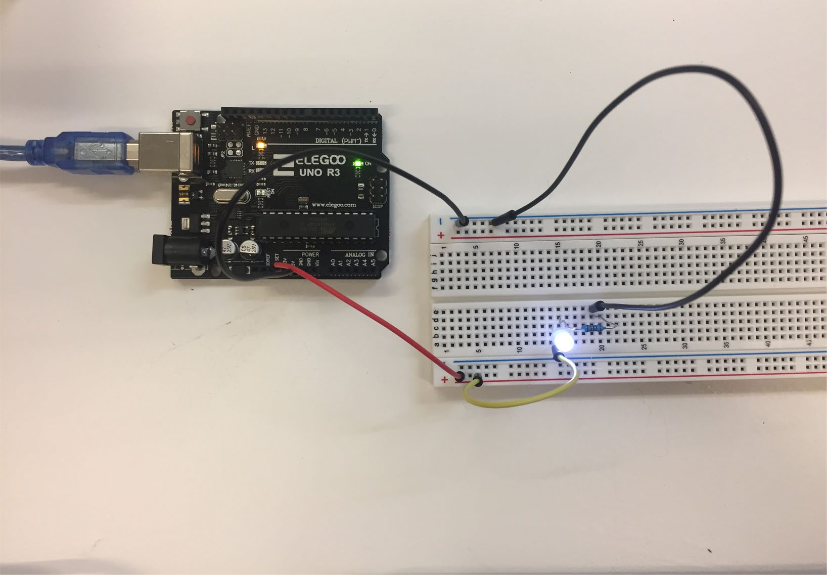
So here's my first LED (light emitting diode) circuit with the breadboard
they called it a breadboard because initially it was made of wood which is non-conductive...
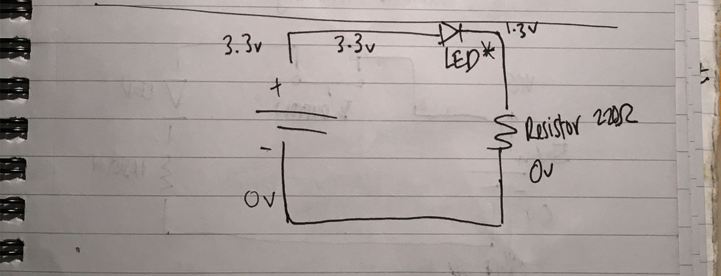
and here's the schematic drawing


sensors
interaction generates a reaction
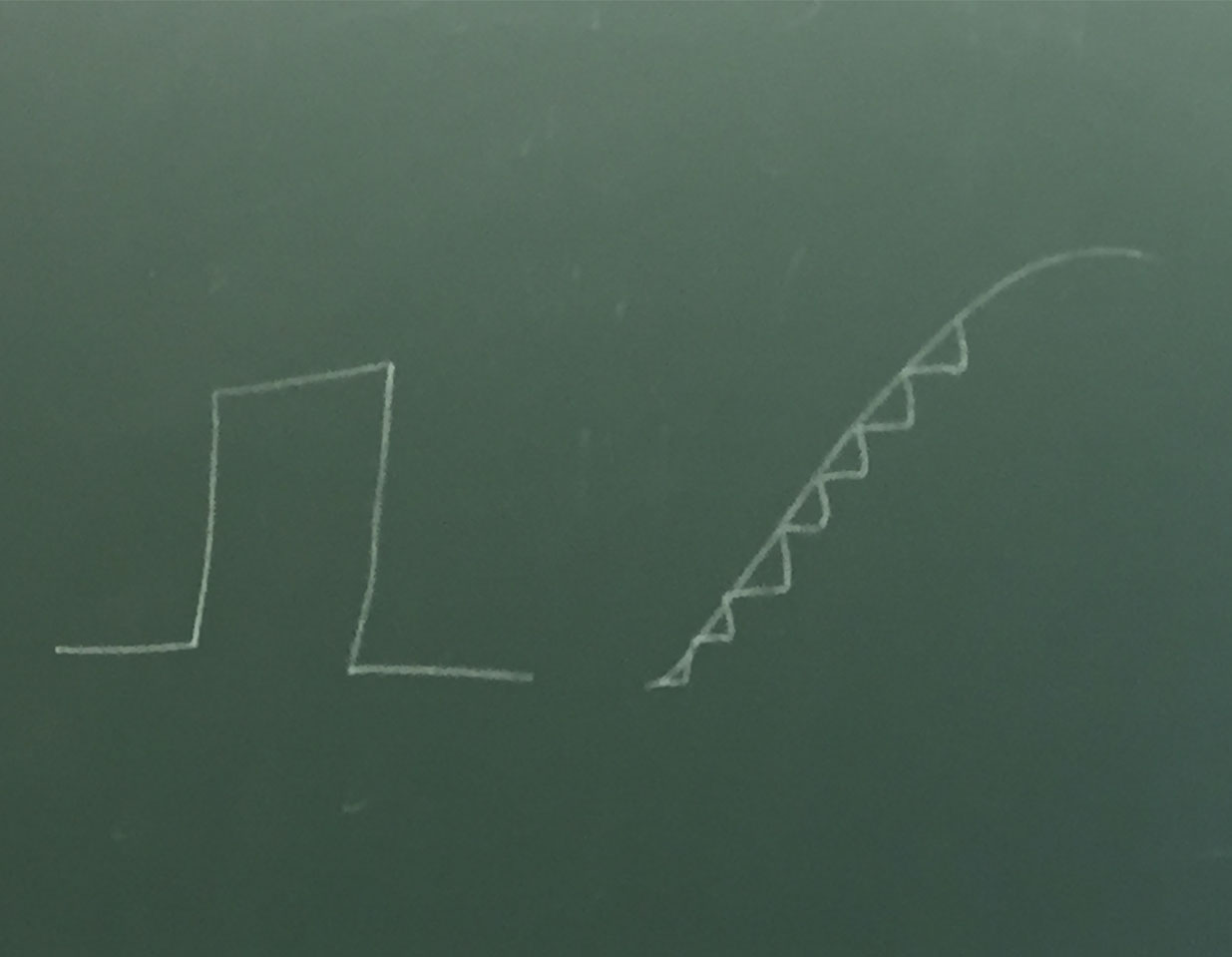
(left) Digital vs Analogue (right)
- digital sensors are either on or off (open or closed)
- all values from 0-1023 (analogue sensor is a resistor by itself); min GND - max VCC
So from the curves and steps in the drawing I can undersand that one binary digital value = a way more fluid analogue range of values
digital sensor
Here's my design sketch for a glove fan..
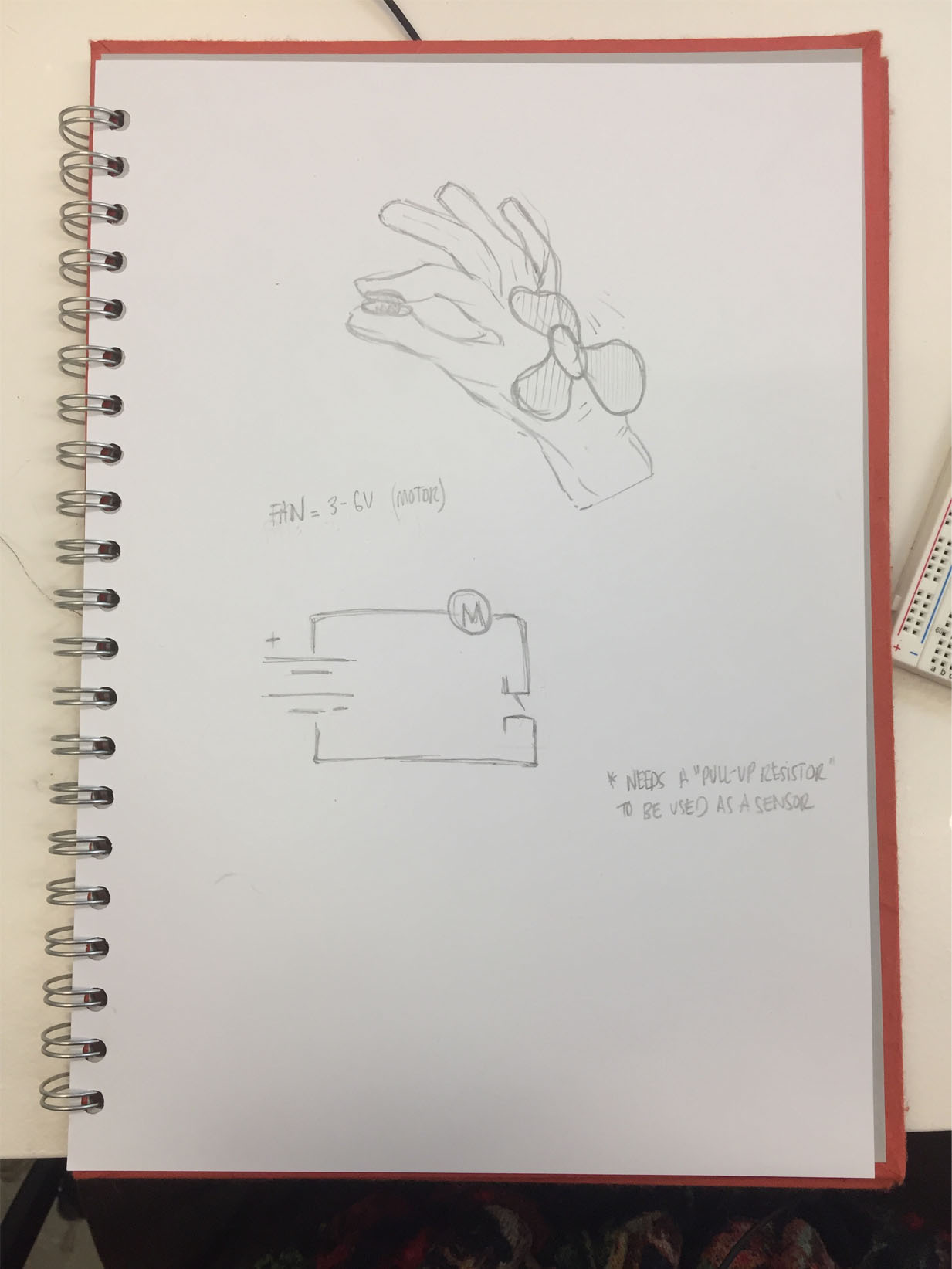
The idea is that it is worn like a watch and the sensors in the finger tips turn it on and off
For this sample I am using conductive thread and copper polyester taffeta for the fingertip switch point.
Here's the fan working from the Arduino
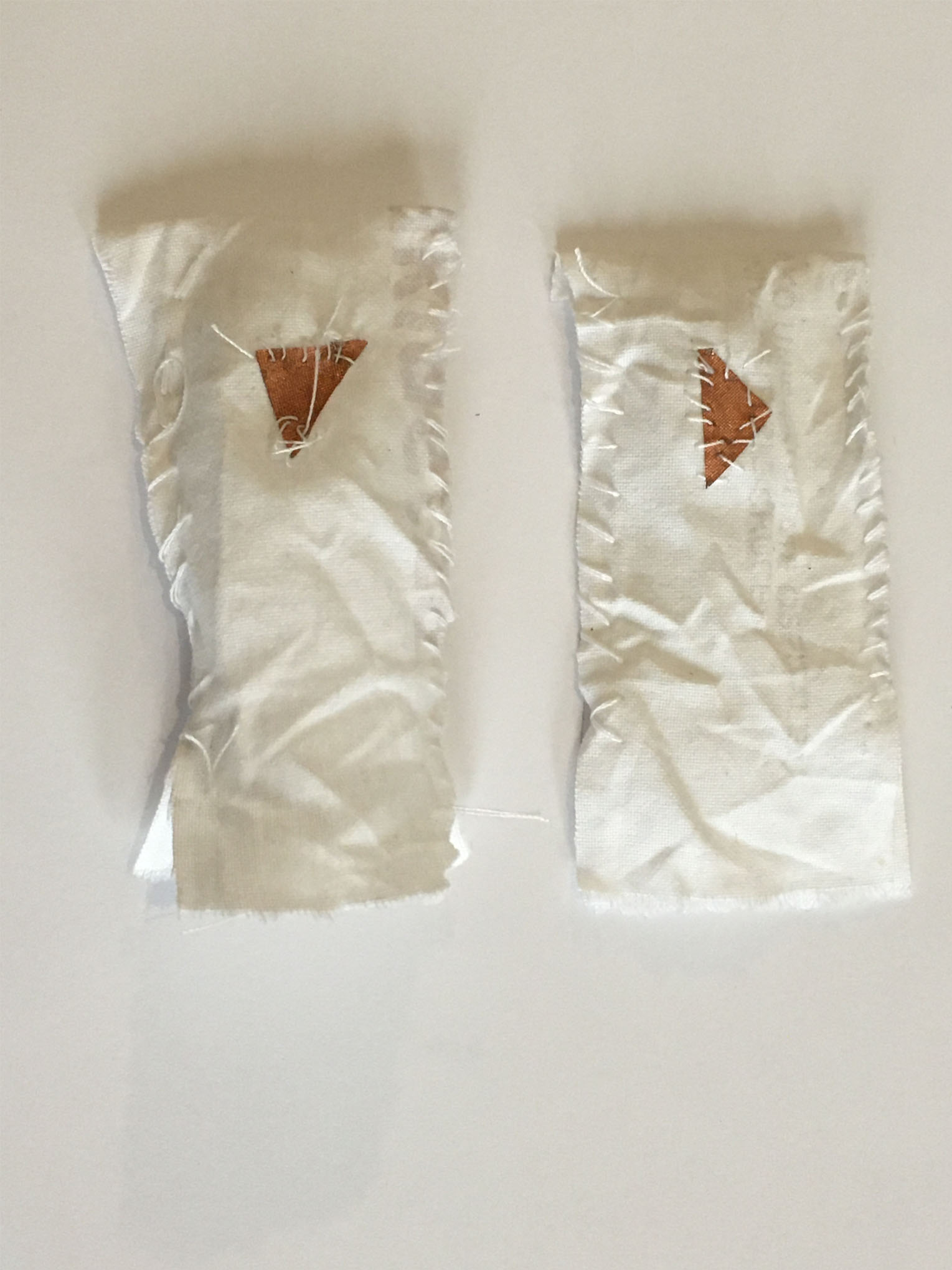
In the prototype I do the finger and thumb, sewing the copper tape on the finger tips
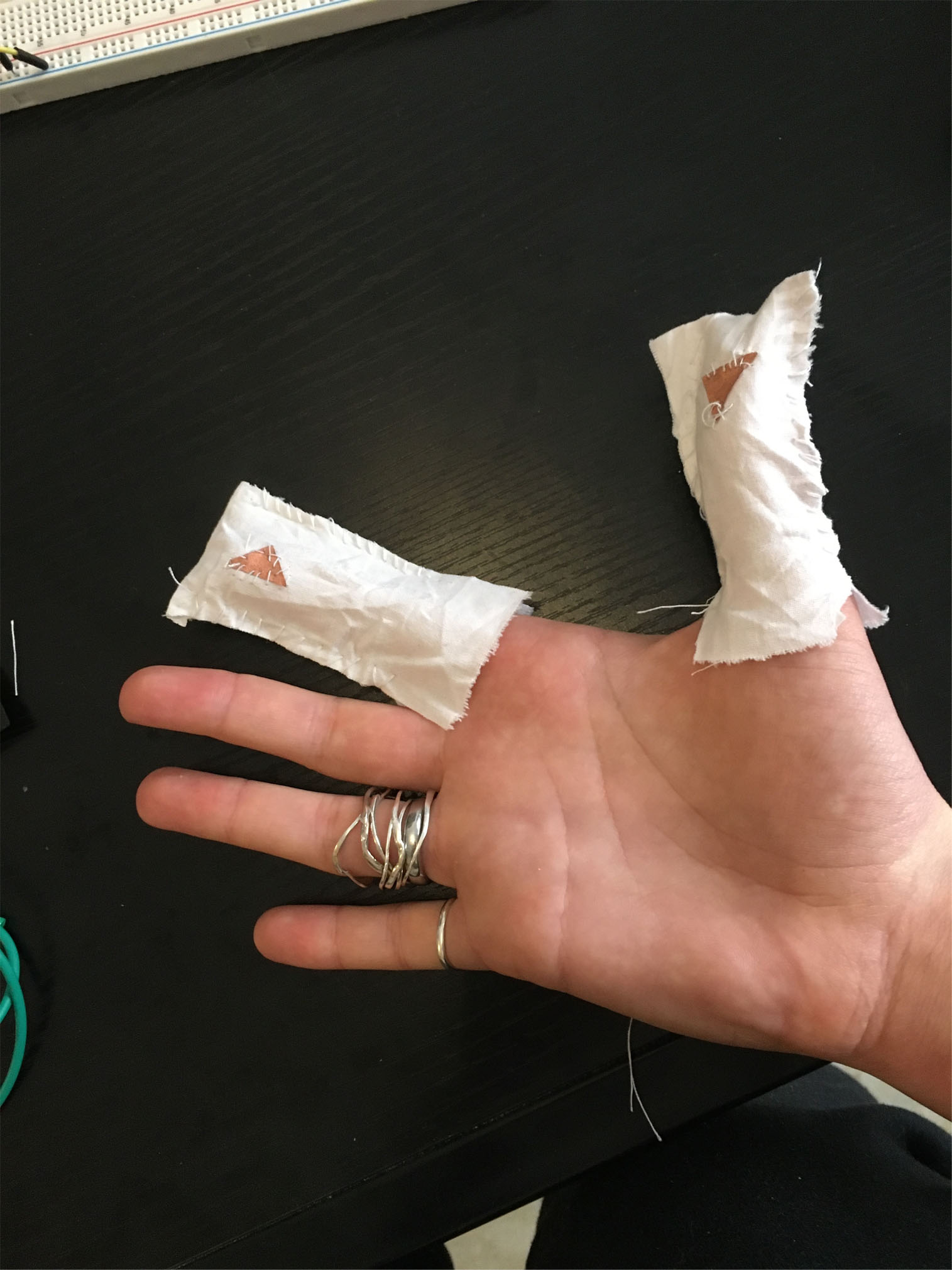
- this is a digital sensor because the sensors are a switch turning the fan (motor) on or off
arduino
By mapping this in Arduino you can see for sure that this is a digital circuit - of course it only goes on and off anyway but the readings also only appear with 0 or 1.
The coding works with abbreviations and equations/ like reading a key on a map
- int = integer
- setup = programming area to explain the terms
- input / output = connections to be programmed
int digital_sensor_pin = 8;     //change the pin, where the sensor is connected?
int digital_sensor_value = 0;

void setup() {
  pinMode(digital_sensor_pin, INPUT); //define the pin as INPUT
  Serial.begin(9600);

}

void loop() {
  // put your main code here, to run repeatedly:
  digital_sensor_value = digitalRead(digital_sensor_pin); // read the sensor

  Serial.println(digital_sensor_value); //print the value
  delay(100);

}
This is the digital reading of the sensor.
analogue sensor
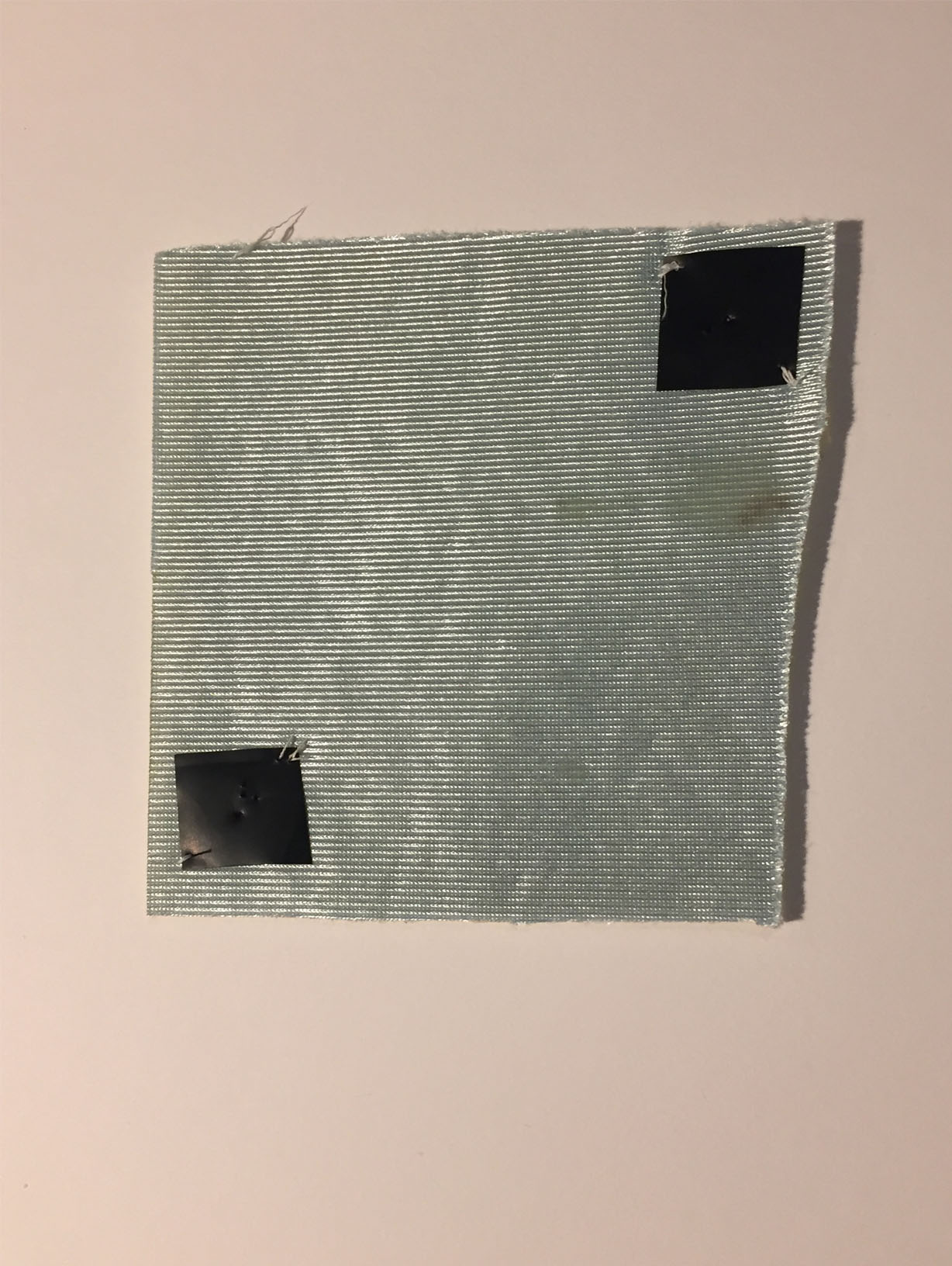
For my analogue sensor I wanted to do a pressure sensitive sensor like a stress ball. I started with tacking the pressure sensitive Velostat on either side of some wadded fabric. Velostat is a packaging material made of a polymeric foil (polyolefins) impregnated with carbon black to make it electrically conductive. It is used for the protection of items or devices that are at risk of electrostatic discharge damage.
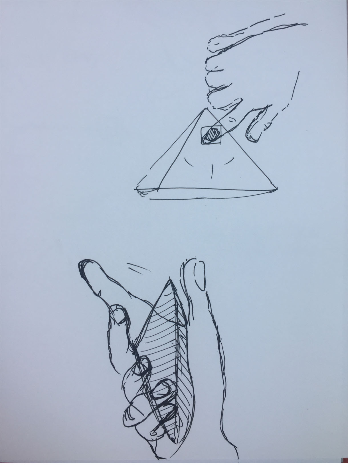
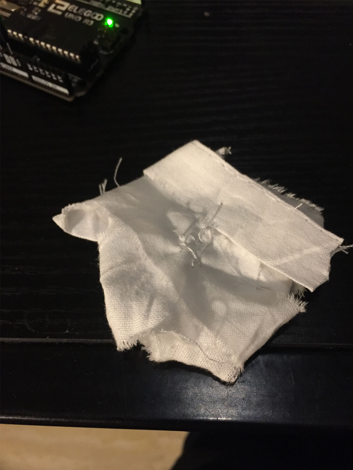
Then stitch it together like a cushion.. adding some homemade wadding - just layered strips of fabric to stuff it with
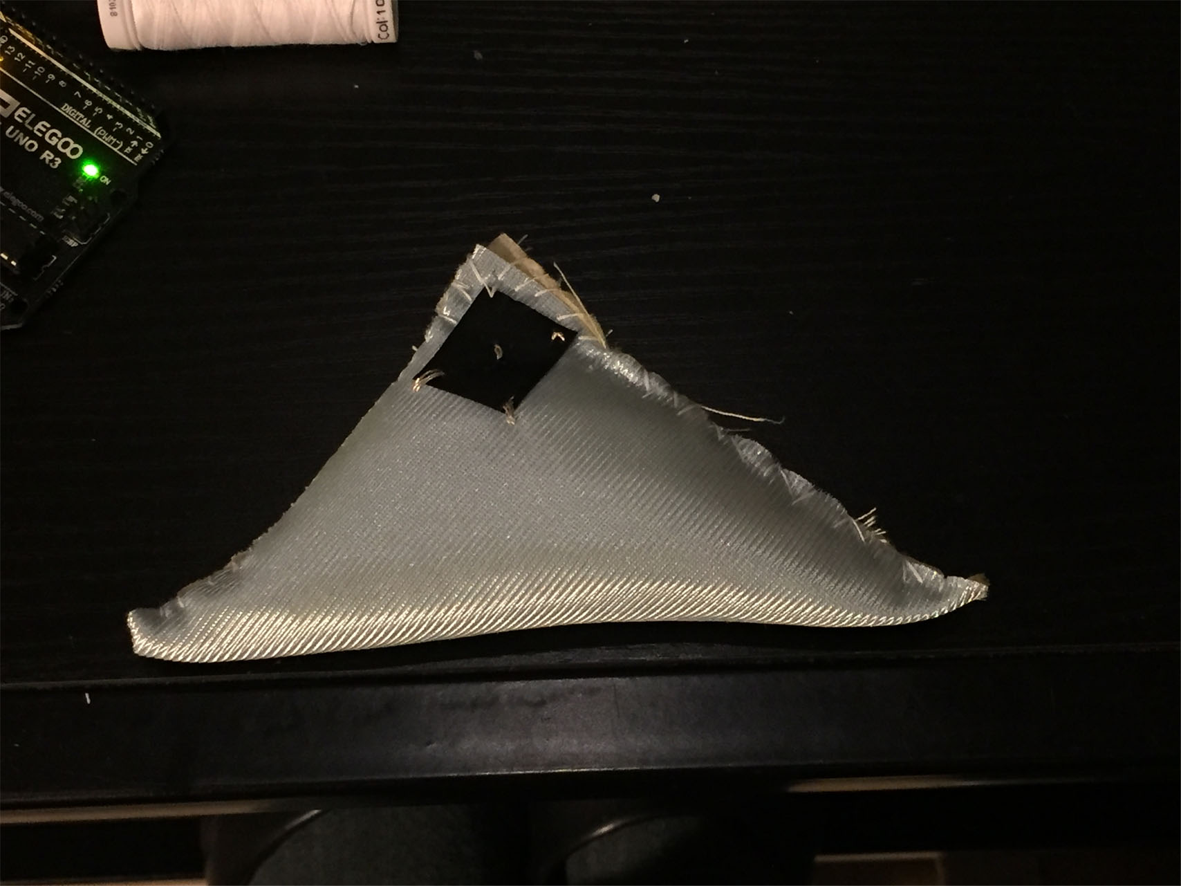
I need to test the sensor connection in the Aduino with these connections:
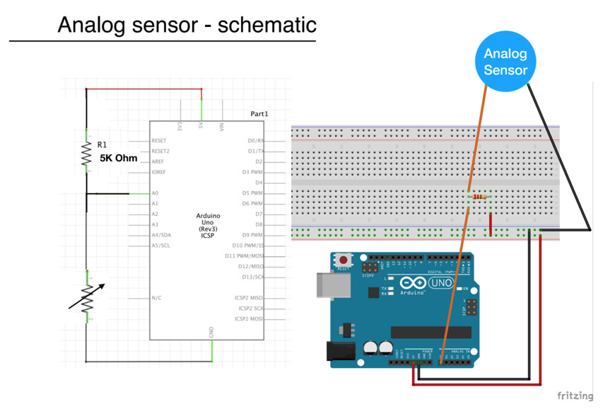
Then program the aduino to display the readings of the analog sensor:
(the analogue sensor PIN is in port A0)
int analog_sensor_pin = A0;   //change the pin, where the sensor is connected?
int analog_sensor_value = 0;

void setup() {
  // put your setup code here, to run once:
  pinMode(analog_sensor_pin, INPUT);
  Serial.begin(9600);

}

void loop() {
  // put your main code here, to run repeatedly:
  analog_sensor_value = analogRead(analog_sensor_pin); //read the Voltage of the pin sensor

  Serial.println(analog_sensor_value); // print the value on the Serial monitor
  delay(100);

}
Here is the sensor in action with the reading!