13 skin electronics
14th - 21st December 2021
13. Skin electronic
intro
- electronics into skin:
- "what does it mean to have skin?"
- cosmetic modification
- self expression
- beauty technology
- seamless technology: conductive makeup (eyelash blink sensors)
- understanding different emotional states
- "chromoskin" interactive eyeshadow
- unconscious "auto-contact" behaviours
- hairware:
- conductive nails
- skin as an interface
- invisible interaction
- human design symbiosis
- gestures
- our relationship between different objects/the actions and movements required of us for these interactions
- learning these movements
- generating gestures
- "interaction with objects used as metaphors that make them potentially interesting tangible interfaces"/cord UIs
- on skin
- temporary tattoos: duo skin
- conscious and unconscious behaviour
- emotional sensors/"affective computing"
- KINISI: skin as interface: FX makeup w sensors/A Skin-Like and Highly Stretchable Optical Fiber Sensor with the Hybrid Coding of Wavelength–Light Intensity
what if there was an installation where your digital clothes are projected or activated and changed w a gesture or 1 surface interaction eg a plaster; would make a statement about the actuality of clothing
- Eslucent; micro-gesture + AI eye lid inteface;
- beauty technology book
- contact lenses
- things to consider: how will they be attached??
-
rachel freire: second skin **
-
interactive organisms
We did this quick mini exercise in the lecture to brain storm some quick ideas for a skin electronic:
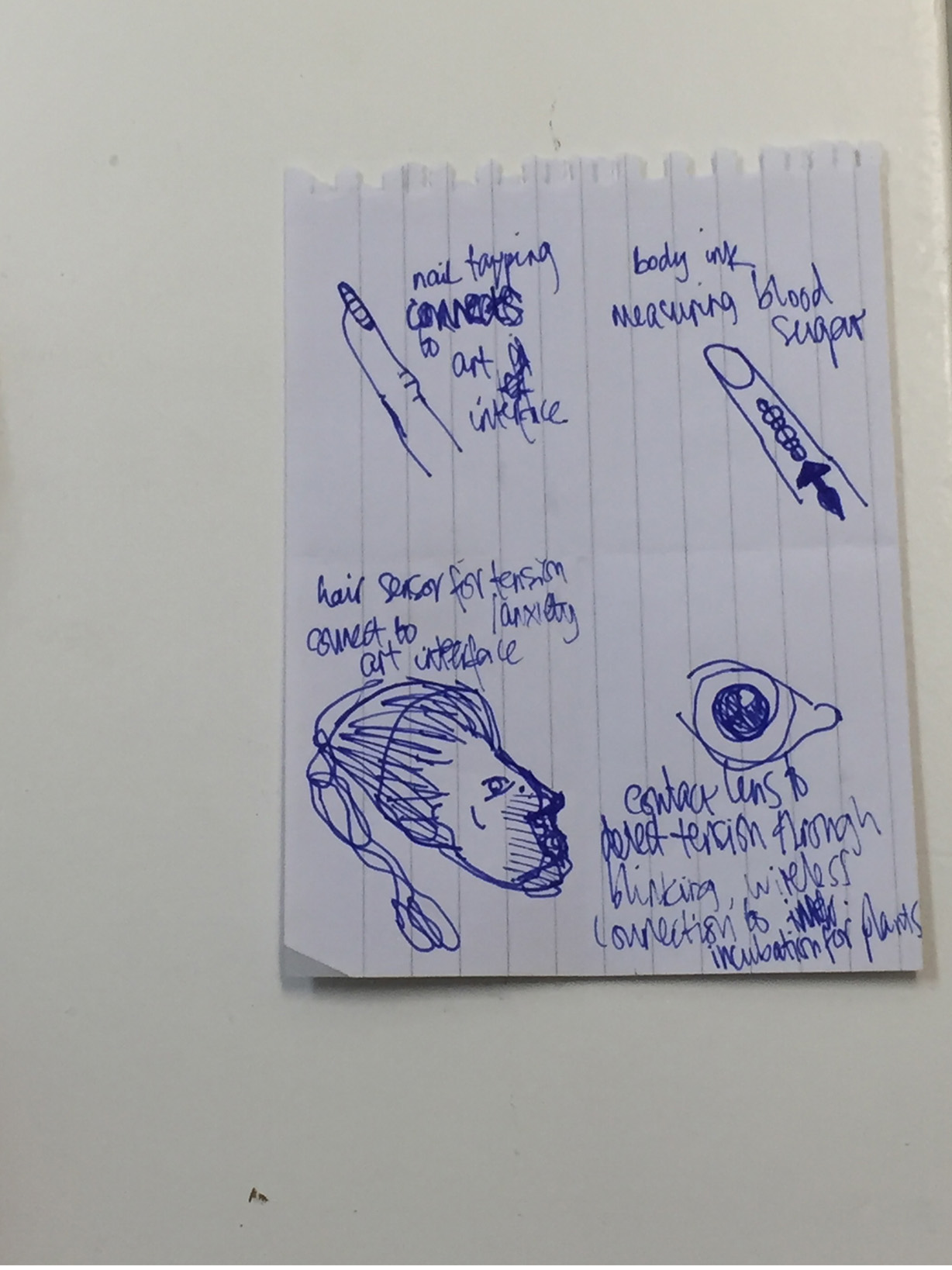
some quick skin interface ideas
workshop notes
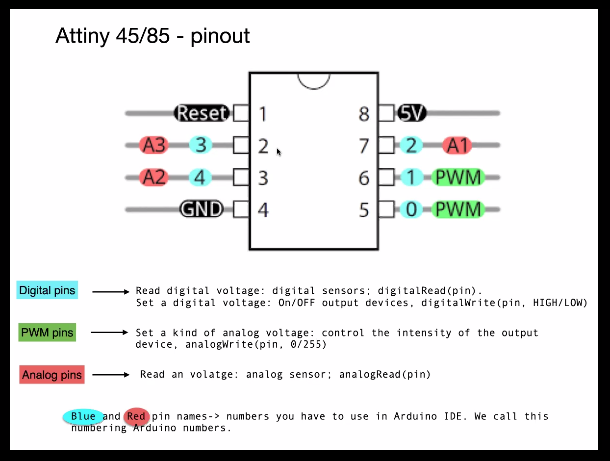
workflow for this assignment: - test and program arduino first - move to ATtiny afterwards; (limit in pins and memory); (each output has rating of miniamps) - calculate miniamps p/hour for voltage calculation
Capacity sensors are touch sensitive (changing capacity); they limit the flow of electrons and accumuluate energy in doing so. They behave like a barrier between the input and the output.
- in the corner of all chips is a 0 which is a mark of the first pin
- physical numbers/legs of pins are not always matched to the input number
- "breakout board" - exposes connection to chips
http://highlowtech.org/?p=1695
https://create.arduino.cc/projecthub/arjun/programming-attiny85-with-arduino-uno-afb829
arduino to ATtiny
So for the skin electronics it makes sense to work with the ATtiny so that it can be worn on the body and doesn't have become an overbearing part of a device.
We have to downsize from the Arduino to the ArduinoITS/ATtiny microcontroller to program the ATtiny. It works as an interpreter and refines the computing for the tinier size.
- install board: tool > board > ATtiny microcontrollers
- clock setting = the speed of memory communicated/read: 8mHz
- burn bootloader will set all the settings/flatten all the commands before you can verity and upload the script
https://www.aranacorp.com/en/create-a-capacitive-sensor-with-arduino/ [for capacitive sensor]
led

blink
led button
led & mini motor
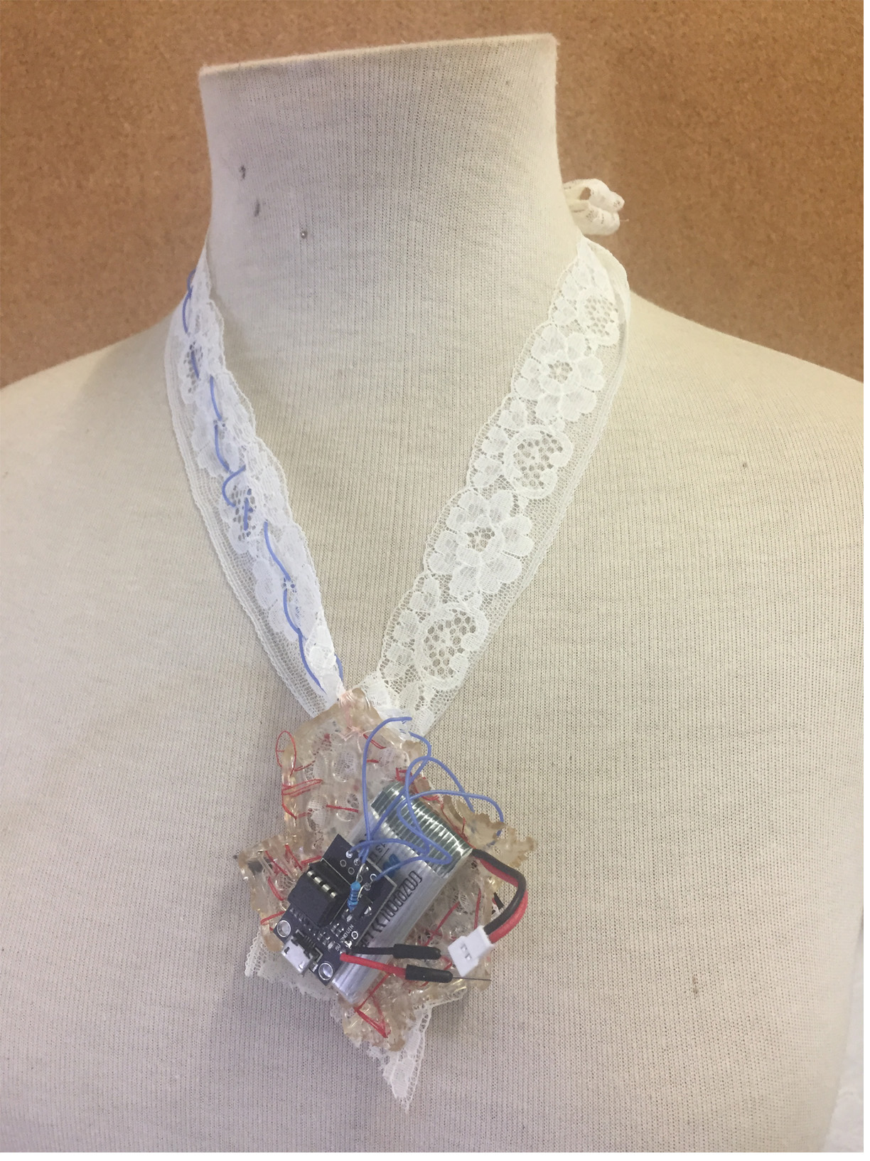
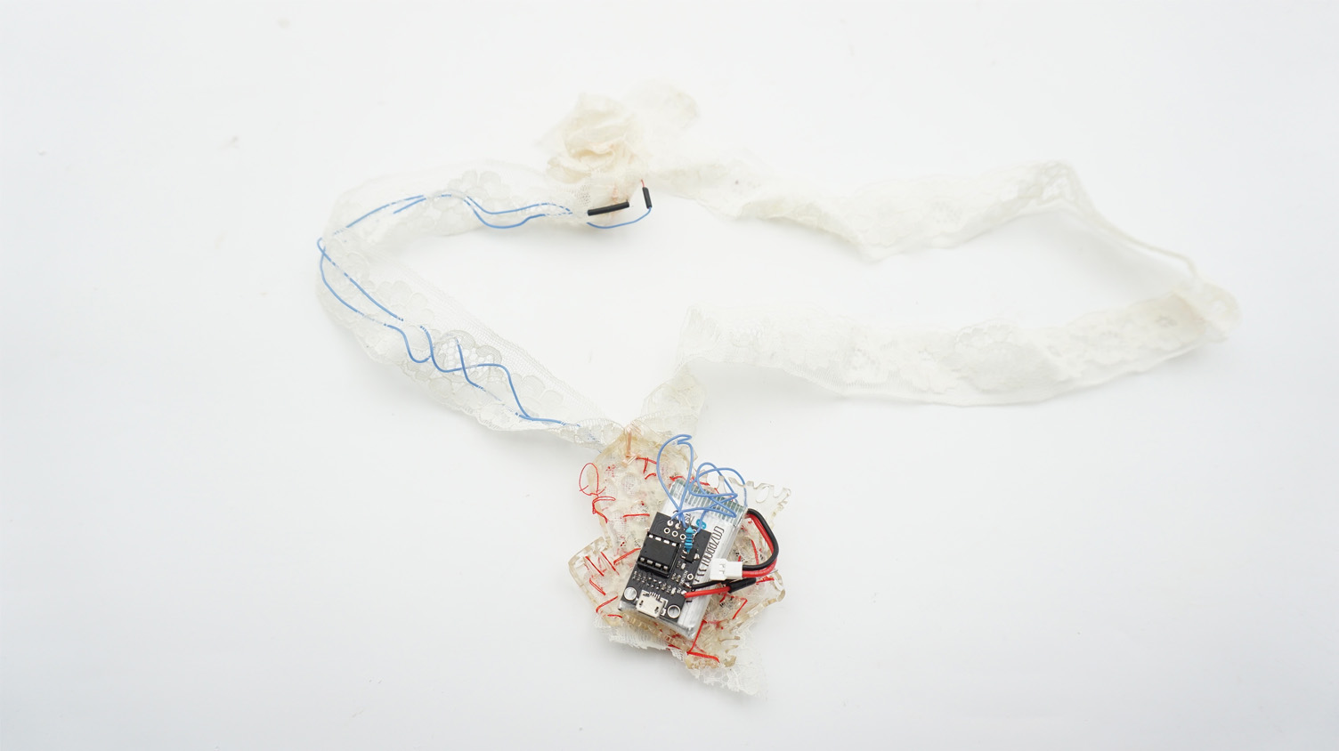
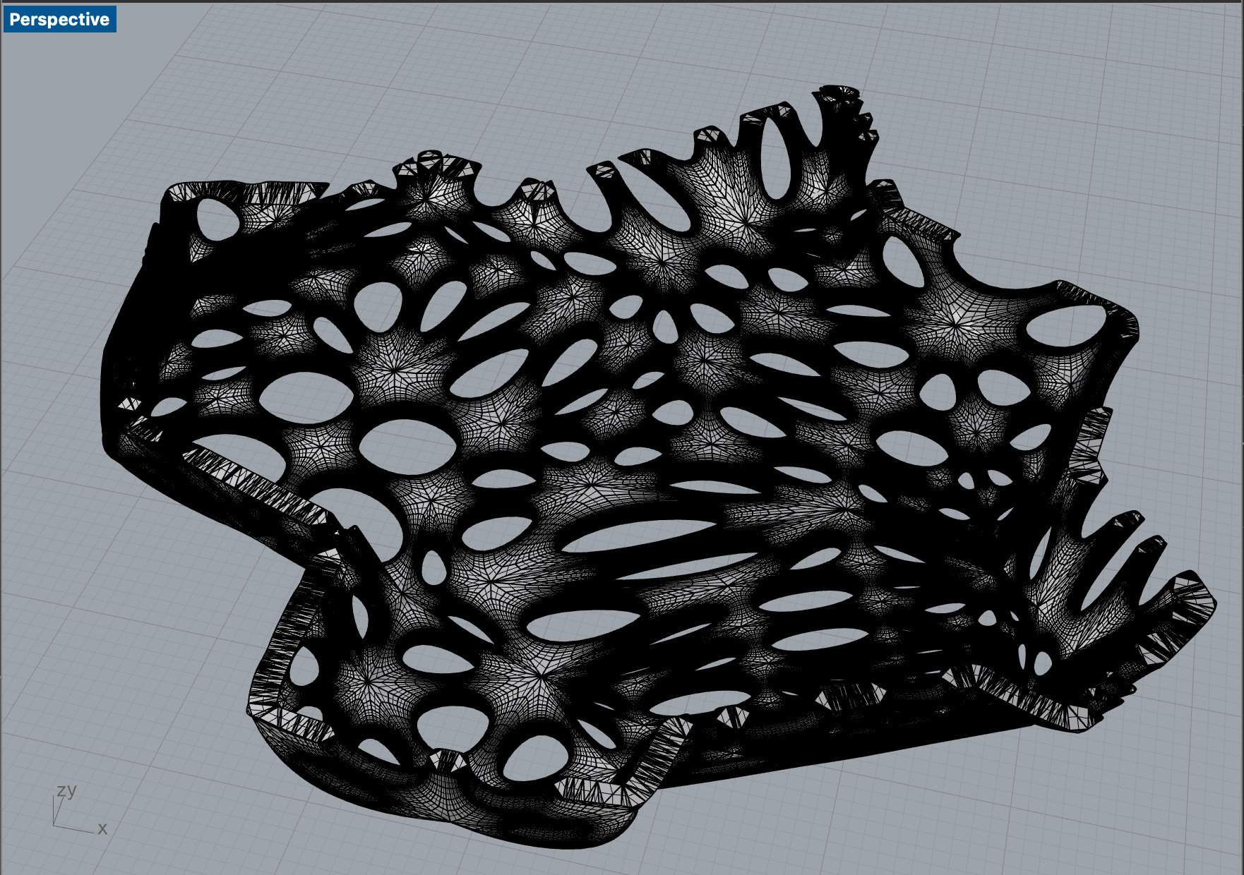
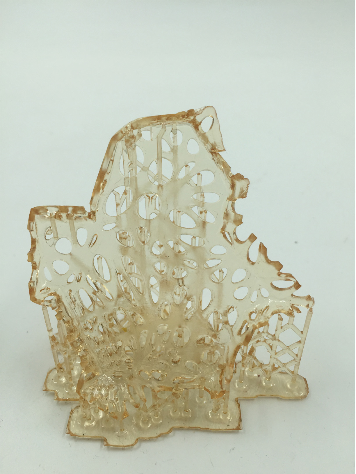
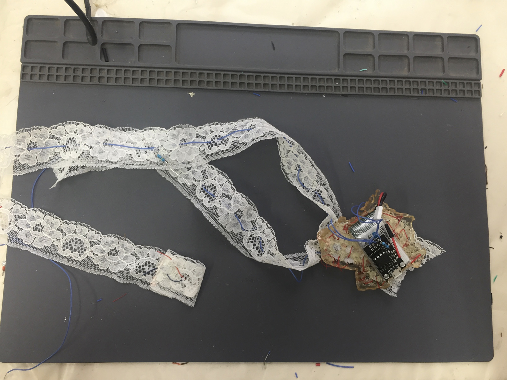
necklace pendant
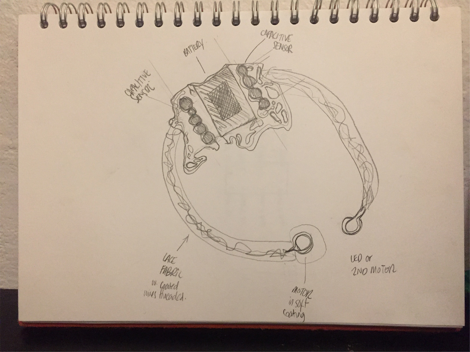
My idea is to make a skin electronic and integrate a capacitive sensor with a vibrating motor in the form of a necklace.
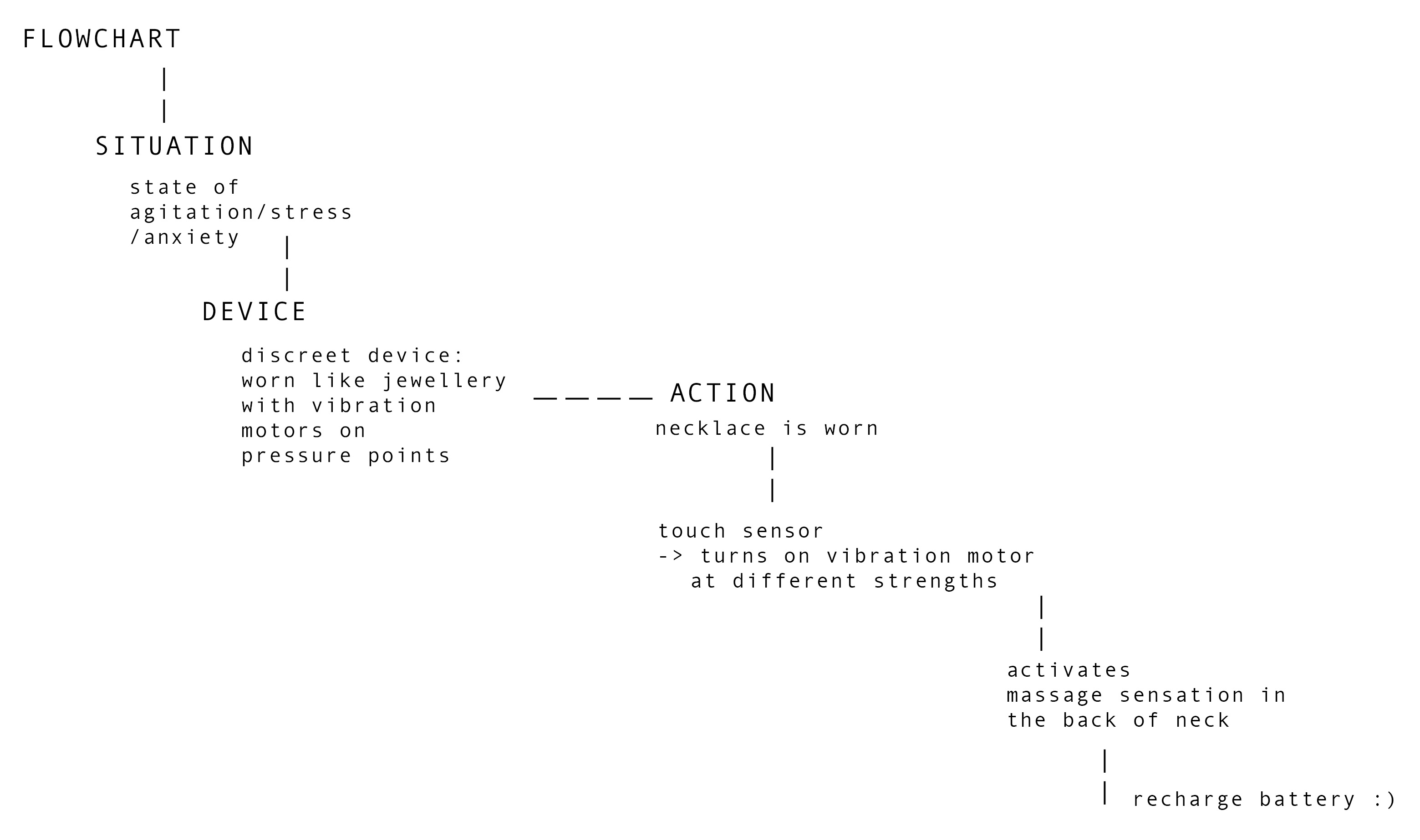
I've been researching pressure points on the body for my final project so it makes sense to try and do a neklace for this assignment.


This massaging tool is an an example of a more practical and utility piece.

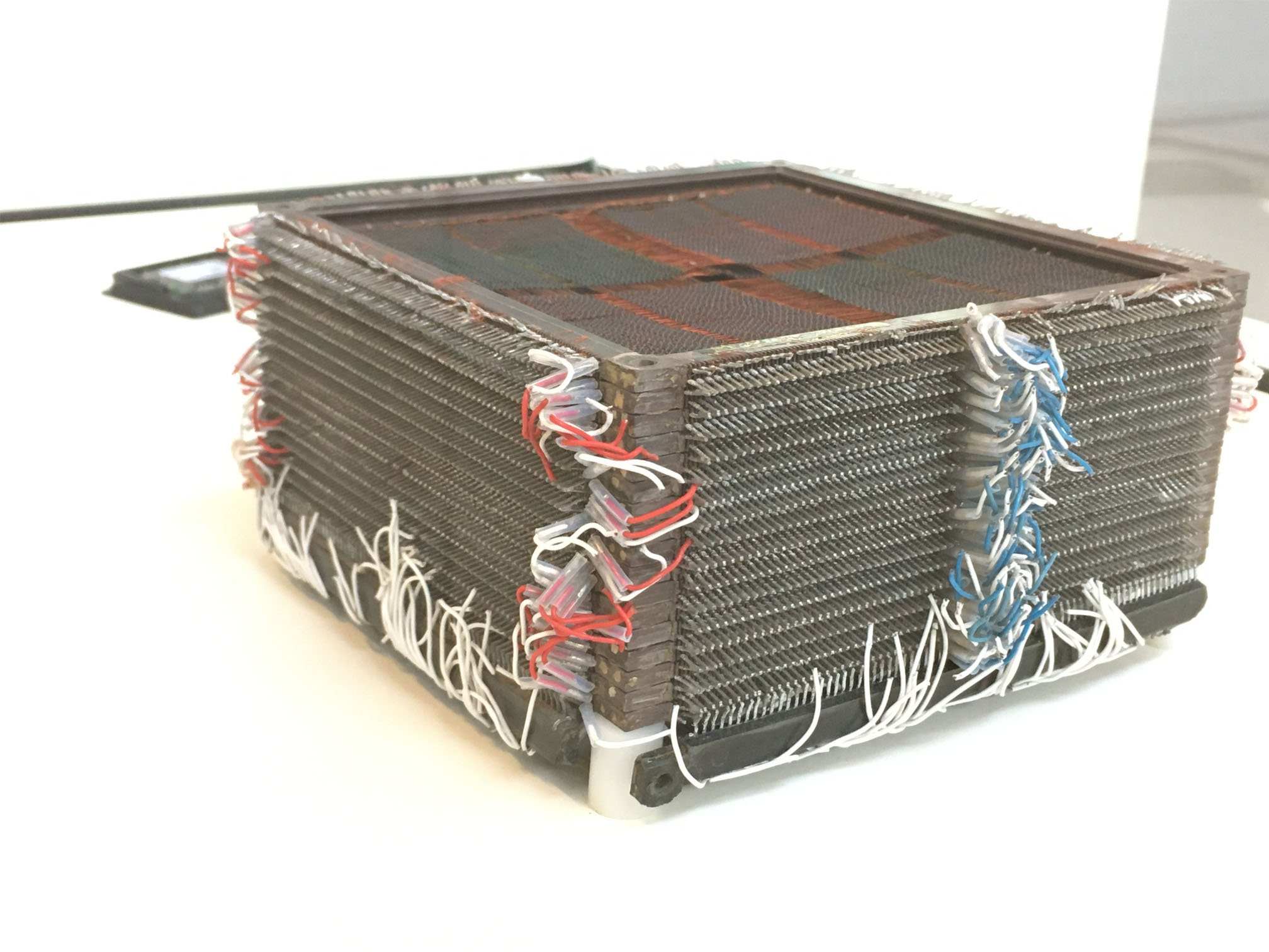
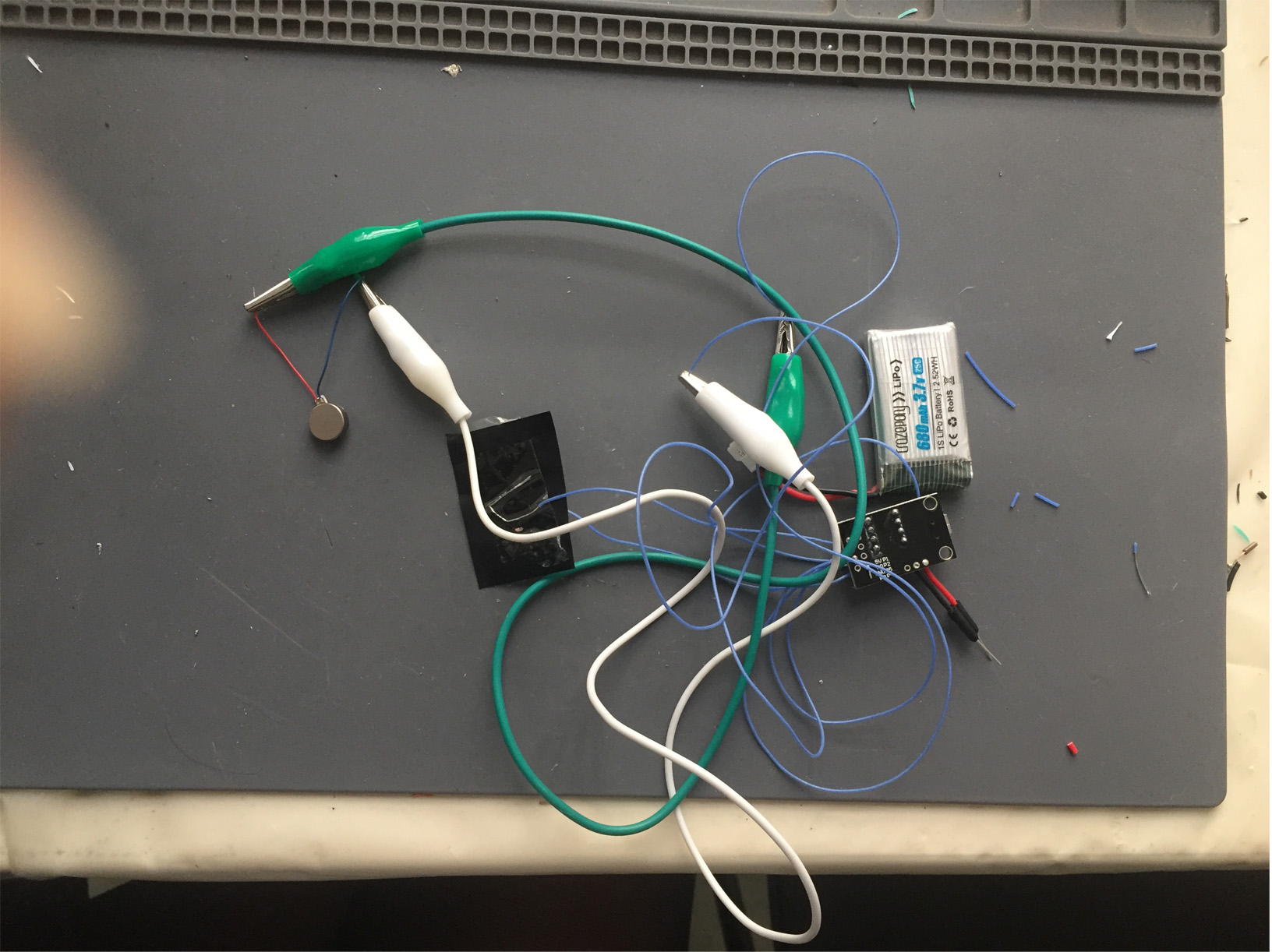
To start with I know I will be using these components so should think about how they will be worn..
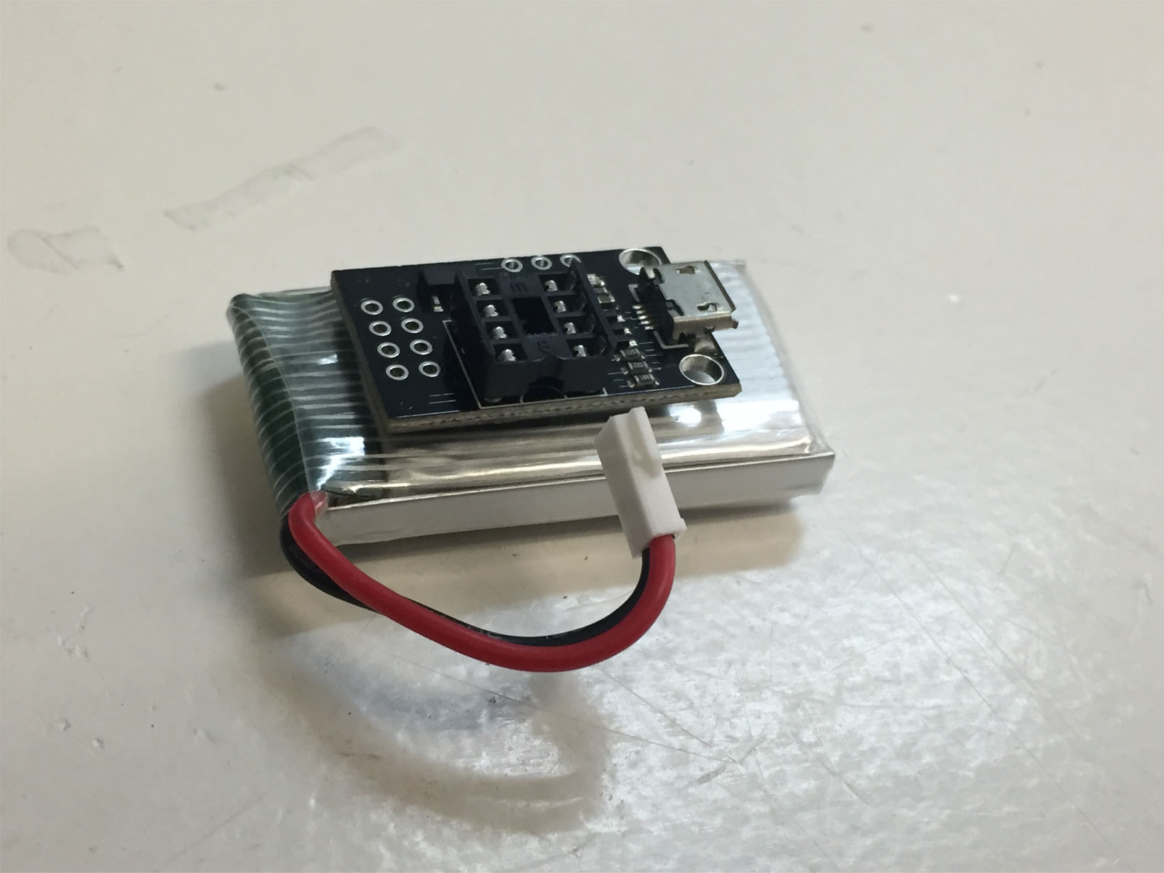
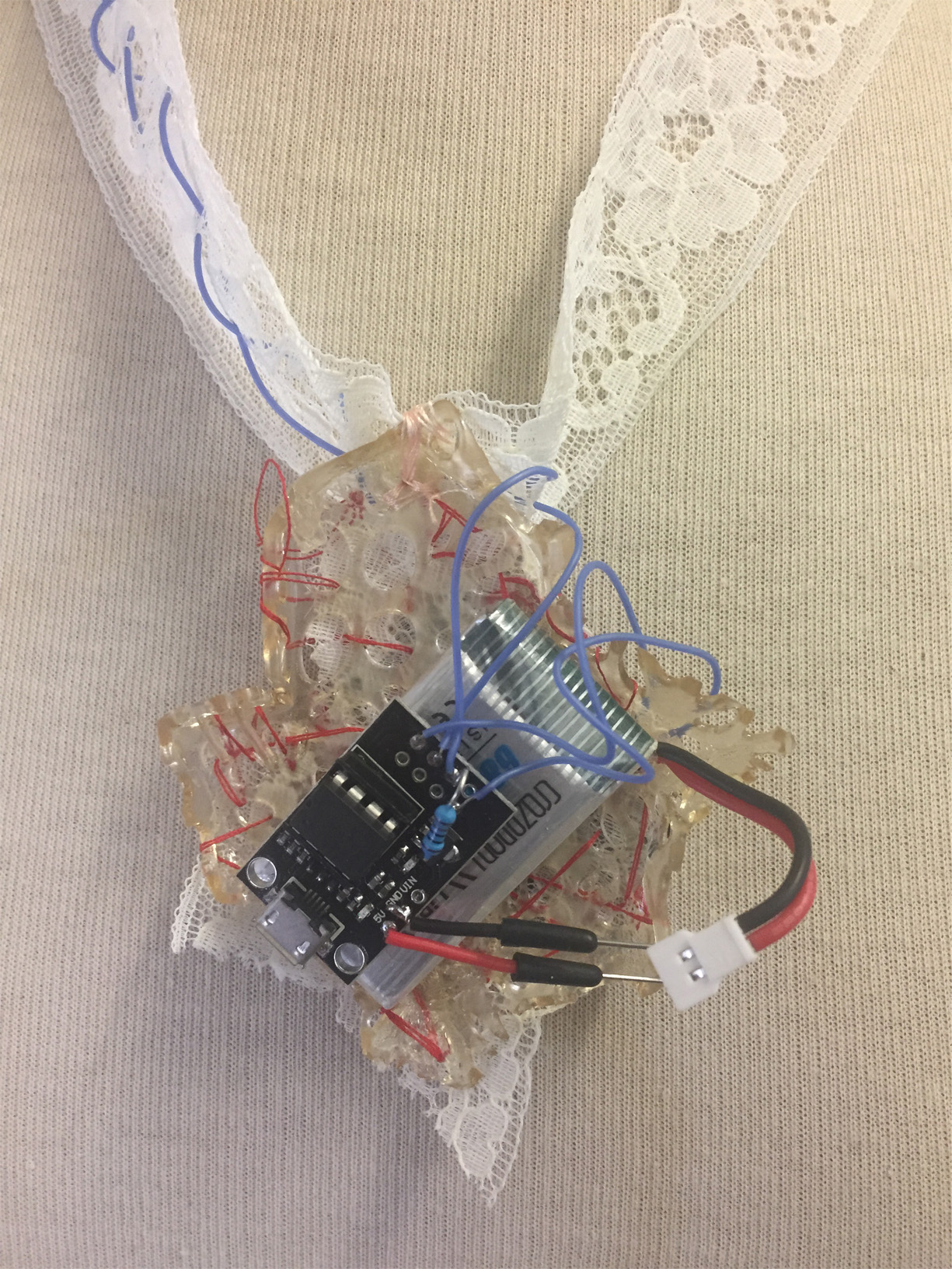
The battery needs to stand alone so in a way it's a good idea to centralise it in the design
i looked at this tutorial to help think of how to contain the battery in a box shape
I measured the battery with the chip to determine how big the pendant should be

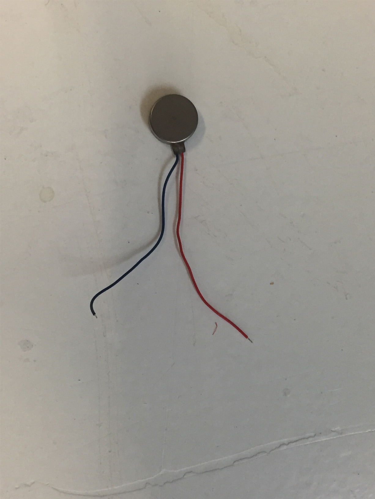
this motor is small and fragile so will maybe need to be secured in some fabric
programming
arduino isp controller script:
// ArduinoISP
// Copyright (c) 2008-2011 Randall Bohn
// If you require a license, see
// https://opensource.org/licenses/bsd-license.php
//
// This sketch turns the Arduino into a AVRISP using the following Arduino pins:
//
// Pin 10 is used to reset the target microcontroller.
//
// By default, the hardware SPI pins MISO, MOSI and SCK are used to communicate
// with the target. On all Arduinos, these pins can be found
// on the ICSP/SPI header:
//
//               MISO °. . 5V (!) Avoid this pin on Due, Zero...
//               SCK   . . MOSI
//                     . . GND
//
// On some Arduinos (Uno,...), pins MOSI, MISO and SCK are the same pins as
// digital pin 11, 12 and 13, respectively. That is why many tutorials instruct
// you to hook up the target to these pins. If you find this wiring more
// practical, have a define USE_OLD_STYLE_WIRING. This will work even when not
// using an Uno. (On an Uno this is not needed).
//
// Alternatively you can use any other digital pin by configuring
// software ('BitBanged') SPI and having appropriate defines for PIN_MOSI,
// PIN_MISO and PIN_SCK.
//
// IMPORTANT: When using an Arduino that is not 5V tolerant (Due, Zero, ...) as
// the programmer, make sure to not expose any of the programmer's pins to 5V.
// A simple way to accomplish this is to power the complete system (programmer
// and target) at 3V3.
//
// Put an LED (with resistor) on the following pins:
// 9: Heartbeat   - shows the programmer is running
// 8: Error       - Lights up if something goes wrong (use red if that makes sense)
// 7: Programming - In communication with the slave
//

#include "Arduino.h"
#undef SERIAL


#define PROG_FLICKER true

// Configure SPI clock (in Hz).
// E.g. for an ATtiny @ 128 kHz: the datasheet states that both the high and low
// SPI clock pulse must be > 2 CPU cycles, so take 3 cycles i.e. divide target
// f_cpu by 6:
//     #define SPI_CLOCK            (128000/6)
//
// A clock slow enough for an ATtiny85 @ 1 MHz, is a reasonable default:

#define SPI_CLOCK       (1000000/6)


// Select hardware or software SPI, depending on SPI clock.
// Currently only for AVR, for other architectures (Due, Zero,...), hardware SPI
// is probably too fast anyway.

#if defined(ARDUINO_ARCH_AVR)

  #if SPI_CLOCK > (F_CPU / 128)
    #define USE_HARDWARE_SPI
  #endif

#endif

// Configure which pins to use:

// The standard pin configuration.
#ifndef ARDUINO_HOODLOADER2

  #define RESET     10 // Use pin 10 to reset the target rather than SS
  #define LED_HB    9
  #define LED_ERR   8
  #define LED_PMODE 7

  // Uncomment following line to use the old Uno style wiring
  // (using pin 11, 12 and 13 instead of the SPI header) on Leonardo, Due...

  // #define USE_OLD_STYLE_WIRING

  #ifdef USE_OLD_STYLE_WIRING

    #define PIN_MOSI    11
    #define PIN_MISO    12
    #define PIN_SCK     13

  #endif

  // HOODLOADER2 means running sketches on the ATmega16U2 serial converter chips
  // on Uno or Mega boards. We must use pins that are broken out:
#else

  #define RESET         4
  #define LED_HB        7
  #define LED_ERR       6
  #define LED_PMODE     5

#endif

// By default, use hardware SPI pins:
#ifndef PIN_MOSI
  #define PIN_MOSI  MOSI
#endif

#ifndef PIN_MISO
  #define PIN_MISO  MISO
#endif

#ifndef PIN_SCK
  #define PIN_SCK   SCK
#endif

// Force bitbanged SPI if not using the hardware SPI pins:
#if (PIN_MISO != MISO) ||  (PIN_MOSI != MOSI) || (PIN_SCK != SCK)
  #undef USE_HARDWARE_SPI
#endif


// Configure the serial port to use.
//
// Prefer the USB virtual serial port (aka. native USB port), if the Arduino has one:
//   - it does not autoreset (except for the magic baud rate of 1200).
//   - it is more reliable because of USB handshaking.
//
// Leonardo and similar have an USB virtual serial port: 'Serial'.
// Due and Zero have an USB virtual serial port: 'SerialUSB'.
//
// On the Due and Zero, 'Serial' can be used too, provided you disable autoreset.
// To use 'Serial': #define SERIAL Serial

#ifdef SERIAL_PORT_USBVIRTUAL
  #define SERIAL SERIAL_PORT_USBVIRTUAL
#else
  #define SERIAL Serial
#endif


// Configure the baud rate:

#define BAUDRATE    19200
// #define BAUDRATE 115200
// #define BAUDRATE 1000000


#define HWVER 2
#define SWMAJ 1
#define SWMIN 18

// STK Definitions
#define STK_OK      0x10
#define STK_FAILED  0x11
#define STK_UNKNOWN 0x12
#define STK_INSYNC  0x14
#define STK_NOSYNC  0x15
#define CRC_EOP     0x20 //ok it is a space...

void pulse(int pin, int times);

#ifdef USE_HARDWARE_SPI
#include "SPI.h"
#else

#define SPI_MODE0 0x00

#if !defined(ARDUINO_API_VERSION) || ARDUINO_API_VERSION != 10001 // A SPISettings class is declared by ArduinoCore-API 1.0.1
class SPISettings {
  public:
    // clock is in Hz
    SPISettings(uint32_t clock, uint8_t bitOrder, uint8_t dataMode) : clockFreq(clock) {
      (void) bitOrder;
      (void) dataMode;
    };

    uint32_t getClockFreq() const {
      return clockFreq;
    }

  private:
    uint32_t clockFreq;
};
#endif  // !defined(ARDUINO_API_VERSION)

class BitBangedSPI {
  public:
    void begin() {
      digitalWrite(PIN_SCK, LOW);
      digitalWrite(PIN_MOSI, LOW);
      pinMode(PIN_SCK, OUTPUT);
      pinMode(PIN_MOSI, OUTPUT);
      pinMode(PIN_MISO, INPUT);
    }

    void beginTransaction(SPISettings settings) {
      pulseWidth = (500000 + settings.getClockFreq() - 1) / settings.getClockFreq();
      if (pulseWidth == 0) {
        pulseWidth = 1;
      }
    }

    void end() {}

    uint8_t transfer(uint8_t b) {
      for (unsigned int i = 0; i < 8; ++i) {
        digitalWrite(PIN_MOSI, (b & 0x80) ? HIGH : LOW);
        digitalWrite(PIN_SCK, HIGH);
        delayMicroseconds(pulseWidth);
        b = (b << 1) | digitalRead(PIN_MISO);
        digitalWrite(PIN_SCK, LOW); // slow pulse
        delayMicroseconds(pulseWidth);
      }
      return b;
    }

  private:
    unsigned long pulseWidth; // in microseconds
};

static BitBangedSPI SPI;

#endif

void setup() {
  SERIAL.begin(BAUDRATE);

  pinMode(LED_PMODE, OUTPUT);
  pulse(LED_PMODE, 2);
  pinMode(LED_ERR, OUTPUT);
  pulse(LED_ERR, 2);
  pinMode(LED_HB, OUTPUT);
  pulse(LED_HB, 2);

}

int ISPError = 0;
int pmode = 0;
// address for reading and writing, set by 'U' command
unsigned int here;
uint8_t buff[256]; // global block storage

#define beget16(addr) (*addr * 256 + *(addr+1) )
typedef struct param {
  uint8_t devicecode;
  uint8_t revision;
  uint8_t progtype;
  uint8_t parmode;
  uint8_t polling;
  uint8_t selftimed;
  uint8_t lockbytes;
  uint8_t fusebytes;
  uint8_t flashpoll;
  uint16_t eeprompoll;
  uint16_t pagesize;
  uint16_t eepromsize;
  uint32_t flashsize;
}
parameter;

parameter param;

// this provides a heartbeat on pin 9, so you can tell the software is running.
uint8_t hbval = 128;
int8_t hbdelta = 8;
void heartbeat() {
  static unsigned long last_time = 0;
  unsigned long now = millis();
  if ((now - last_time) < 40) {
    return;
  }
  last_time = now;
  if (hbval > 192) {
    hbdelta = -hbdelta;
  }
  if (hbval < 32) {
    hbdelta = -hbdelta;
  }
  hbval += hbdelta;
  analogWrite(LED_HB, hbval);
}

static bool rst_active_high;

void reset_target(bool reset) {
  digitalWrite(RESET, ((reset && rst_active_high) || (!reset && !rst_active_high)) ? HIGH : LOW);
}

void loop(void) {
  // is pmode active?
  if (pmode) {
    digitalWrite(LED_PMODE, HIGH);
  } else {
    digitalWrite(LED_PMODE, LOW);
  }
  // is there an error?
  if (ISPError) {
    digitalWrite(LED_ERR, HIGH);
  } else {
    digitalWrite(LED_ERR, LOW);
  }

  // light the heartbeat LED
  heartbeat();
  if (SERIAL.available()) {
    avrisp();
  }
}

uint8_t getch() {
  while (!SERIAL.available());
  return SERIAL.read();
}
void fill(int n) {
  for (int x = 0; x < n; x++) {
    buff[x] = getch();
  }
}

#define PTIME 30
void pulse(int pin, int times) {
  do {
    digitalWrite(pin, HIGH);
    delay(PTIME);
    digitalWrite(pin, LOW);
    delay(PTIME);
  } while (times--);
}

void prog_lamp(int state) {
  if (PROG_FLICKER) {
    digitalWrite(LED_PMODE, state);
  }
}

uint8_t spi_transaction(uint8_t a, uint8_t b, uint8_t c, uint8_t d) {
  SPI.transfer(a);
  SPI.transfer(b);
  SPI.transfer(c);
  return SPI.transfer(d);
}

void empty_reply() {
  if (CRC_EOP == getch()) {
    SERIAL.print((char)STK_INSYNC);
    SERIAL.print((char)STK_OK);
  } else {
    ISPError++;
    SERIAL.print((char)STK_NOSYNC);
  }
}

void breply(uint8_t b) {
  if (CRC_EOP == getch()) {
    SERIAL.print((char)STK_INSYNC);
    SERIAL.print((char)b);
    SERIAL.print((char)STK_OK);
  } else {
    ISPError++;
    SERIAL.print((char)STK_NOSYNC);
  }
}

void get_version(uint8_t c) {
  switch (c) {
    case 0x80:
      breply(HWVER);
      break;
    case 0x81:
      breply(SWMAJ);
      break;
    case 0x82:
      breply(SWMIN);
      break;
    case 0x93:
      breply('S'); // serial programmer
      break;
    default:
      breply(0);
  }
}

void set_parameters() {
  // call this after reading parameter packet into buff[]
  param.devicecode = buff[0];
  param.revision   = buff[1];
  param.progtype   = buff[2];
  param.parmode    = buff[3];
  param.polling    = buff[4];
  param.selftimed  = buff[5];
  param.lockbytes  = buff[6];
  param.fusebytes  = buff[7];
  param.flashpoll  = buff[8];
  // ignore buff[9] (= buff[8])
  // following are 16 bits (big endian)
  param.eeprompoll = beget16(&buff[10]);
  param.pagesize   = beget16(&buff[12]);
  param.eepromsize = beget16(&buff[14]);

  // 32 bits flashsize (big endian)
  param.flashsize = buff[16] * 0x01000000
                    + buff[17] * 0x00010000
                    + buff[18] * 0x00000100
                    + buff[19];

  // AVR devices have active low reset, AT89Sx are active high
  rst_active_high = (param.devicecode >= 0xe0);
}

void start_pmode() {

  // Reset target before driving PIN_SCK or PIN_MOSI

  // SPI.begin() will configure SS as output, so SPI master mode is selected.
  // We have defined RESET as pin 10, which for many Arduinos is not the SS pin.
  // So we have to configure RESET as output here,
  // (reset_target() first sets the correct level)
  reset_target(true);
  pinMode(RESET, OUTPUT);
  SPI.begin();
  SPI.beginTransaction(SPISettings(SPI_CLOCK, MSBFIRST, SPI_MODE0));

  // See AVR datasheets, chapter "SERIAL_PRG Programming Algorithm":

  // Pulse RESET after PIN_SCK is low:
  digitalWrite(PIN_SCK, LOW);
  delay(20); // discharge PIN_SCK, value arbitrarily chosen
  reset_target(false);
  // Pulse must be minimum 2 target CPU clock cycles so 100 usec is ok for CPU
  // speeds above 20 KHz
  delayMicroseconds(100);
  reset_target(true);

  // Send the enable programming command:
  delay(50); // datasheet: must be > 20 msec
  spi_transaction(0xAC, 0x53, 0x00, 0x00);
  pmode = 1;
}

void end_pmode() {
  SPI.end();
  // We're about to take the target out of reset so configure SPI pins as input
  pinMode(PIN_MOSI, INPUT);
  pinMode(PIN_SCK, INPUT);
  reset_target(false);
  pinMode(RESET, INPUT);
  pmode = 0;
}

void universal() {
  uint8_t ch;

  fill(4);
  ch = spi_transaction(buff[0], buff[1], buff[2], buff[3]);
  breply(ch);
}

void flash(uint8_t hilo, unsigned int addr, uint8_t data) {
  spi_transaction(0x40 + 8 * hilo,
                  addr >> 8 & 0xFF,
                  addr & 0xFF,
                  data);
}
void commit(unsigned int addr) {
  if (PROG_FLICKER) {
    prog_lamp(LOW);
  }
  spi_transaction(0x4C, (addr >> 8) & 0xFF, addr & 0xFF, 0);
  if (PROG_FLICKER) {
    delay(PTIME);
    prog_lamp(HIGH);
  }
}

unsigned int current_page() {
  if (param.pagesize == 32) {
    return here & 0xFFFFFFF0;
  }
  if (param.pagesize == 64) {
    return here & 0xFFFFFFE0;
  }
  if (param.pagesize == 128) {
    return here & 0xFFFFFFC0;
  }
  if (param.pagesize == 256) {
    return here & 0xFFFFFF80;
  }
  return here;
}


void write_flash(int length) {
  fill(length);
  if (CRC_EOP == getch()) {
    SERIAL.print((char) STK_INSYNC);
    SERIAL.print((char) write_flash_pages(length));
  } else {
    ISPError++;
    SERIAL.print((char) STK_NOSYNC);
  }
}

uint8_t write_flash_pages(int length) {
  int x = 0;
  unsigned int page = current_page();
  while (x < length) {
    if (page != current_page()) {
      commit(page);
      page = current_page();
    }
    flash(LOW, here, buff[x++]);
    flash(HIGH, here, buff[x++]);
    here++;
  }

  commit(page);

  return STK_OK;
}

#define EECHUNK (32)
uint8_t write_eeprom(unsigned int length) {
  // here is a word address, get the byte address
  unsigned int start = here * 2;
  unsigned int remaining = length;
  if (length > param.eepromsize) {
    ISPError++;
    return STK_FAILED;
  }
  while (remaining > EECHUNK) {
    write_eeprom_chunk(start, EECHUNK);
    start += EECHUNK;
    remaining -= EECHUNK;
  }
  write_eeprom_chunk(start, remaining);
  return STK_OK;
}
// write (length) bytes, (start) is a byte address
uint8_t write_eeprom_chunk(unsigned int start, unsigned int length) {
  // this writes byte-by-byte, page writing may be faster (4 bytes at a time)
  fill(length);
  prog_lamp(LOW);
  for (unsigned int x = 0; x < length; x++) {
    unsigned int addr = start + x;
    spi_transaction(0xC0, (addr >> 8) & 0xFF, addr & 0xFF, buff[x]);
    delay(45);
  }
  prog_lamp(HIGH);
  return STK_OK;
}

void program_page() {
  char result = (char) STK_FAILED;
  unsigned int length = 256 * getch();
  length += getch();
  char memtype = getch();
  // flash memory @here, (length) bytes
  if (memtype == 'F') {
    write_flash(length);
    return;
  }
  if (memtype == 'E') {
    result = (char)write_eeprom(length);
    if (CRC_EOP == getch()) {
      SERIAL.print((char) STK_INSYNC);
      SERIAL.print(result);
    } else {
      ISPError++;
      SERIAL.print((char) STK_NOSYNC);
    }
    return;
  }
  SERIAL.print((char)STK_FAILED);
  return;
}

uint8_t flash_read(uint8_t hilo, unsigned int addr) {
  return spi_transaction(0x20 + hilo * 8,
                         (addr >> 8) & 0xFF,
                         addr & 0xFF,
                         0);
}

char flash_read_page(int length) {
  for (int x = 0; x < length; x += 2) {
    uint8_t low = flash_read(LOW, here);
    SERIAL.print((char) low);
    uint8_t high = flash_read(HIGH, here);
    SERIAL.print((char) high);
    here++;
  }
  return STK_OK;
}

char eeprom_read_page(int length) {
  // here again we have a word address
  int start = here * 2;
  for (int x = 0; x < length; x++) {
    int addr = start + x;
    uint8_t ee = spi_transaction(0xA0, (addr >> 8) & 0xFF, addr & 0xFF, 0xFF);
    SERIAL.print((char) ee);
  }
  return STK_OK;
}

void read_page() {
  char result = (char)STK_FAILED;
  int length = 256 * getch();
  length += getch();
  char memtype = getch();
  if (CRC_EOP != getch()) {
    ISPError++;
    SERIAL.print((char) STK_NOSYNC);
    return;
  }
  SERIAL.print((char) STK_INSYNC);
  if (memtype == 'F') {
    result = flash_read_page(length);
  }
  if (memtype == 'E') {
    result = eeprom_read_page(length);
  }
  SERIAL.print(result);
}

void read_signature() {
  if (CRC_EOP != getch()) {
    ISPError++;
    SERIAL.print((char) STK_NOSYNC);
    return;
  }
  SERIAL.print((char) STK_INSYNC);
  uint8_t high = spi_transaction(0x30, 0x00, 0x00, 0x00);
  SERIAL.print((char) high);
  uint8_t middle = spi_transaction(0x30, 0x00, 0x01, 0x00);
  SERIAL.print((char) middle);
  uint8_t low = spi_transaction(0x30, 0x00, 0x02, 0x00);
  SERIAL.print((char) low);
  SERIAL.print((char) STK_OK);
}
//////////////////////////////////////////
//////////////////////////////////////////


////////////////////////////////////
////////////////////////////////////
void avrisp() {
  uint8_t ch = getch();
  switch (ch) {
    case '0': // signon
      ISPError = 0;
      empty_reply();
      break;
    case '1':
      if (getch() == CRC_EOP) {
        SERIAL.print((char) STK_INSYNC);
        SERIAL.print("AVR ISP");
        SERIAL.print((char) STK_OK);
      } else {
        ISPError++;
        SERIAL.print((char) STK_NOSYNC);
      }
      break;
    case 'A':
      get_version(getch());
      break;
    case 'B':
      fill(20);
      set_parameters();
      empty_reply();
      break;
    case 'E': // extended parameters - ignore for now
      fill(5);
      empty_reply();
      break;
    case 'P':
      if (!pmode) {
        start_pmode();
      }
      empty_reply();
      break;
    case 'U': // set address (word)
      here = getch();
      here += 256 * getch();
      empty_reply();
      break;

    case 0x60: //STK_PROG_FLASH
      getch(); // low addr
      getch(); // high addr
      empty_reply();
      break;
    case 0x61: //STK_PROG_DATA
      getch(); // data
      empty_reply();
      break;

    case 0x64: //STK_PROG_PAGE
      program_page();
      break;

    case 0x74: //STK_READ_PAGE 't'
      read_page();
      break;

    case 'V': //0x56
      universal();
      break;
    case 'Q': //0x51
      ISPError = 0;
      end_pmode();
      empty_reply();
      break;

    case 0x75: //STK_READ_SIGN 'u'
      read_signature();
      break;

    // expecting a command, not CRC_EOP
    // this is how we can get back in sync
    case CRC_EOP:
      ISPError++;
      SERIAL.print((char) STK_NOSYNC);
      break;

    // anything else we will return STK_UNKNOWN
    default:
      ISPError++;
      if (CRC_EOP == getch()) {
        SERIAL.print((char)STK_UNKNOWN);
      } else {
        SERIAL.print((char)STK_NOSYNC);
      }
  }
}
led blink on attiny
/*
  Blink

  Turns an LED on for one second, then off for one second, repeatedly.

  Most Arduinos have an on-board LED you can control. On the UNO, MEGA and ZERO
  it is attached to digital pin 13, on MKR1000 on pin 6. LED_BUILTIN is set to
  the correct LED pin independent of which board is used.
  If you want to know what pin the on-board LED is connected to on your Arduino
  model, check the Technical Specs of your board at:
  https://www.arduino.cc/en/Main/Products

  modified 8 May 2014
  by Scott Fitzgerald
  modified 2 Sep 2016
  by Arturo Guadalupi
  modified 8 Sep 2016
  by Colby Newman

  This example code is in the public domain.

  https://www.arduino.cc/en/Tutorial/BuiltInExamples/Blink
*/

// the setup function runs once when you press reset or power the board
int led_pin = 2;  //pin of the Led

void setup() {
  // initialize digital pin LED_BUILTIN as an output.
  pinMode(led_pin, OUTPUT);
}

// the loop function runs over and over again forever
void loop() {
  digitalWrite(led_pin, HIGH);   // turn the LED on (HIGH is the voltage level)
  delay(1000);                       // wait for a second
  digitalWrite(led_pin, LOW);    // turn the LED off by making the voltage LOW
  delay(1000);                       // wait for a second
}
attiny blink
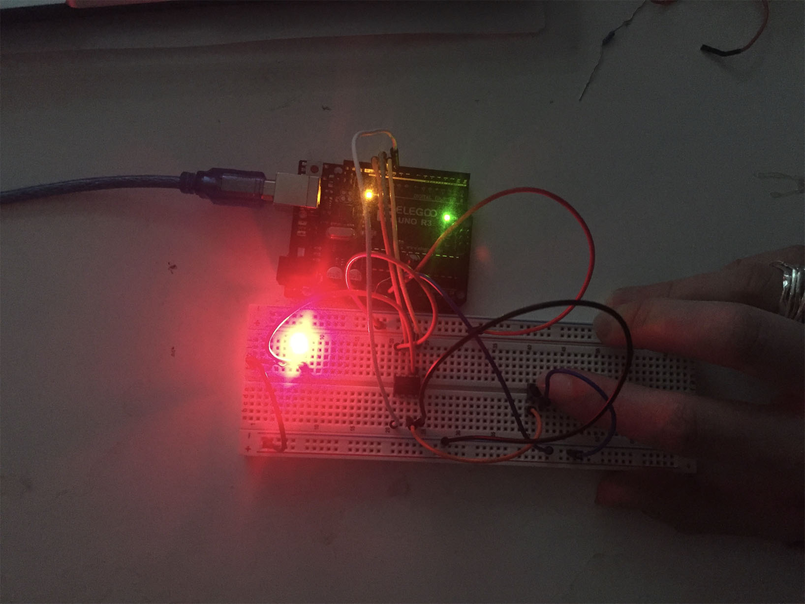
moving on to integrating the motor in the circuit, i looked at this video to try and help me adapt to the consumers in my circuit; see this link for more on that device
in the end i decided to do analog so that the necklace vibration will have a range
/*Emma Pareschi,
 * with this sketch we read the analog sensor connected to pin analog_sensor_pin
 */

int analog_sensor_pin = A2;   //change the pin, where the sensor is connected?
int analog_sensor_value = 0;

int LEDpin = 0;


void setup() {
  // put your setup code here, to run once:
  pinMode(analog_sensor_pin, INPUT);
  //Serial.begin(9600);
  pinMode(LEDpin, OUTPUT);

}

void loop() {
  // put your main code here, to run repeatedly:
  analog_sensor_value = analogRead(analog_sensor_pin); //read the Voltage of the pin sensor
  analog_sensor_value = constrain(analog_sensor_value, 0, 255);
  //Serial.println(analog_sensor_value); // print the value on the Serial monitor


  analogWrite(LEDpin, analog_sensor_value);


  delay(100);

}
analog_sensor_value = constrain(analog_sensor_value, 0, 255);
adding contrain restricts the value of the sensor
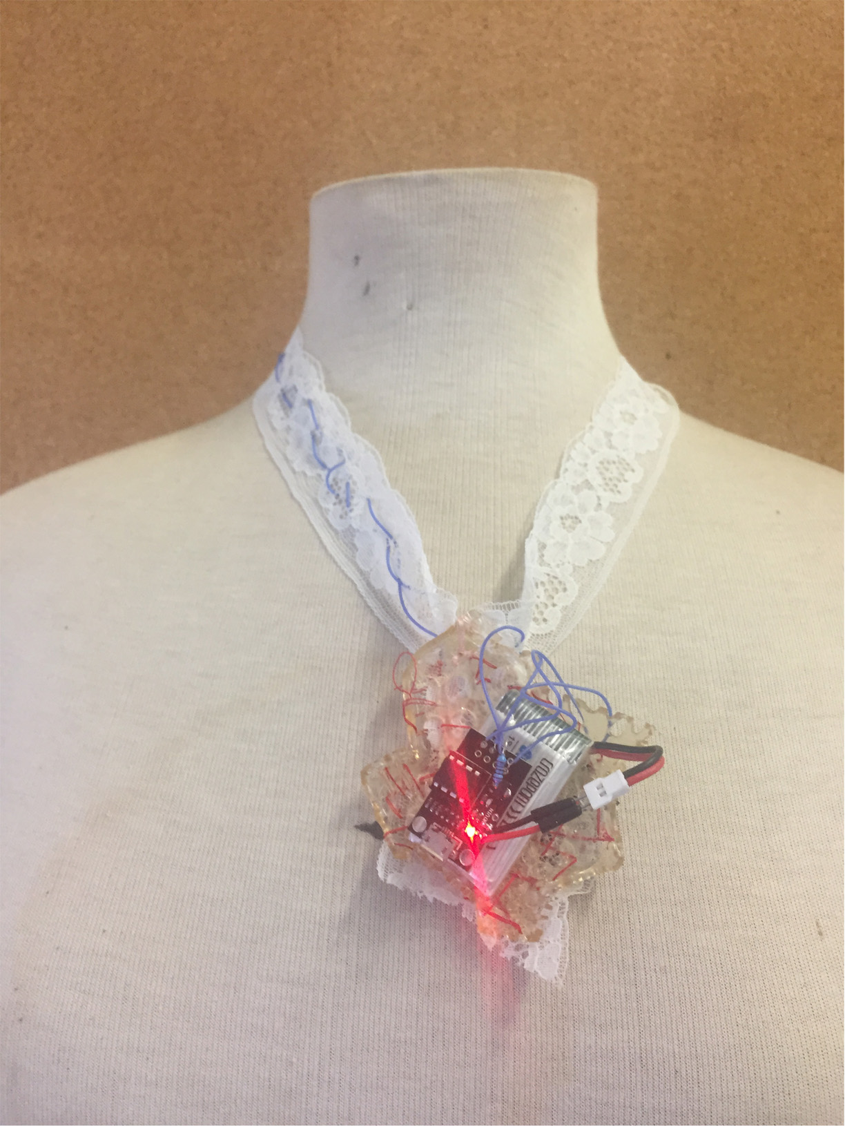
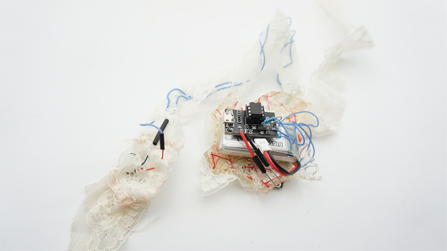
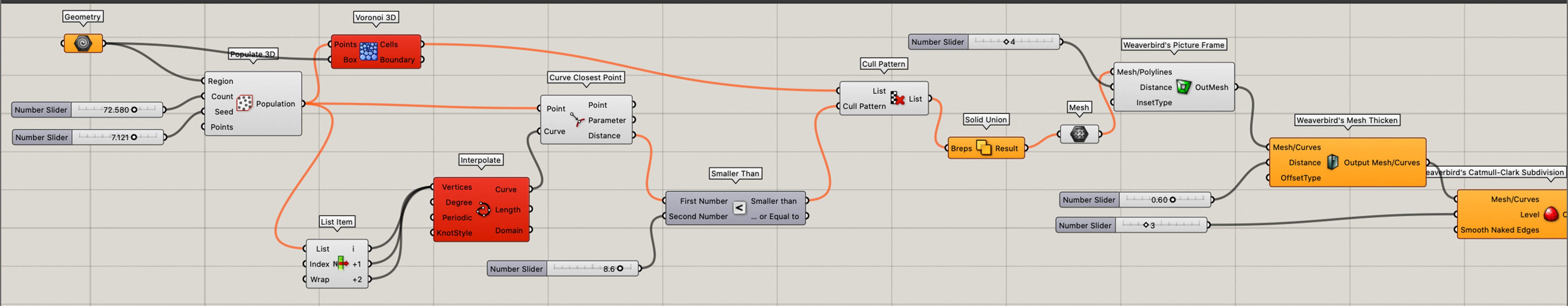
construction
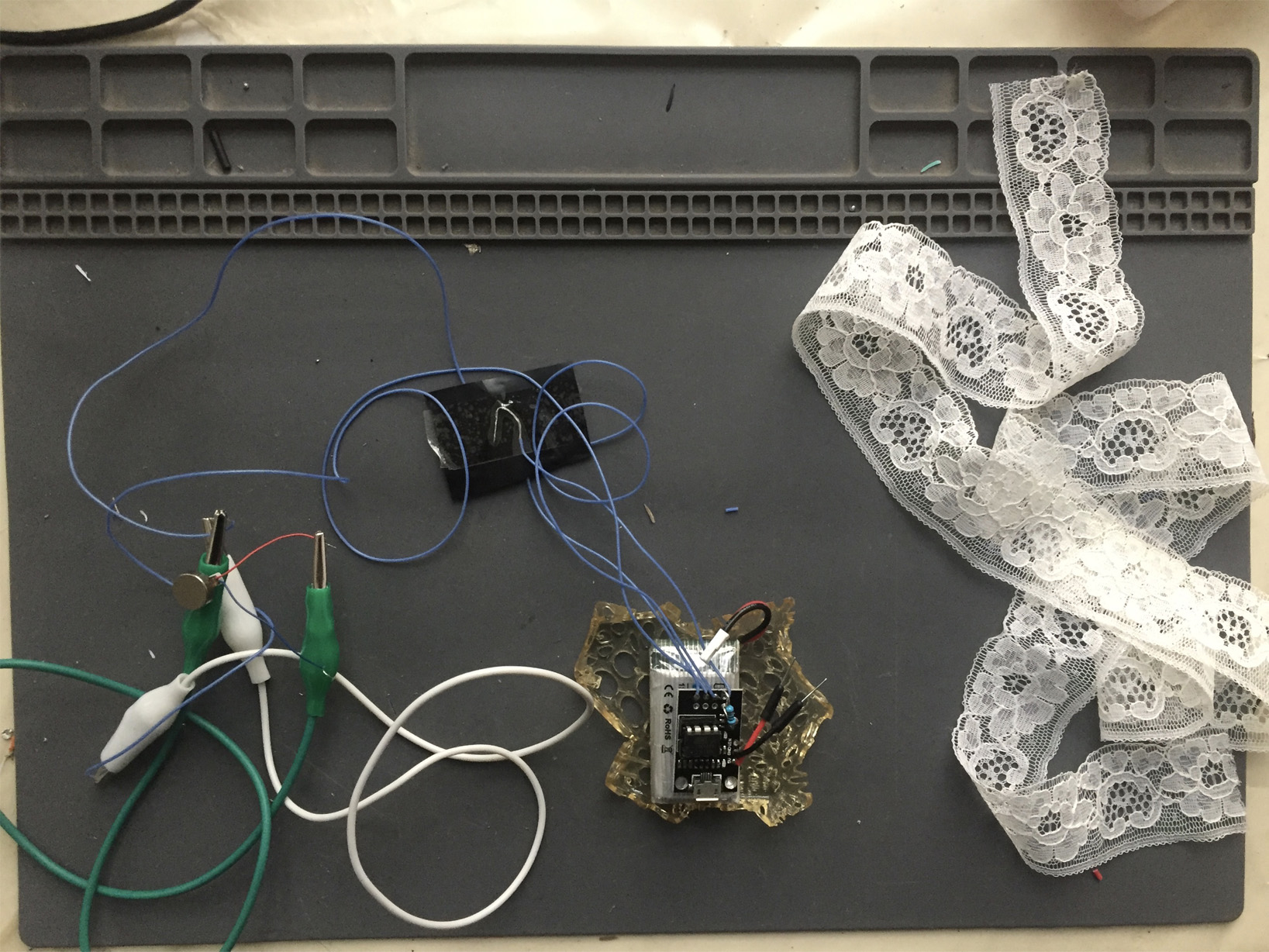
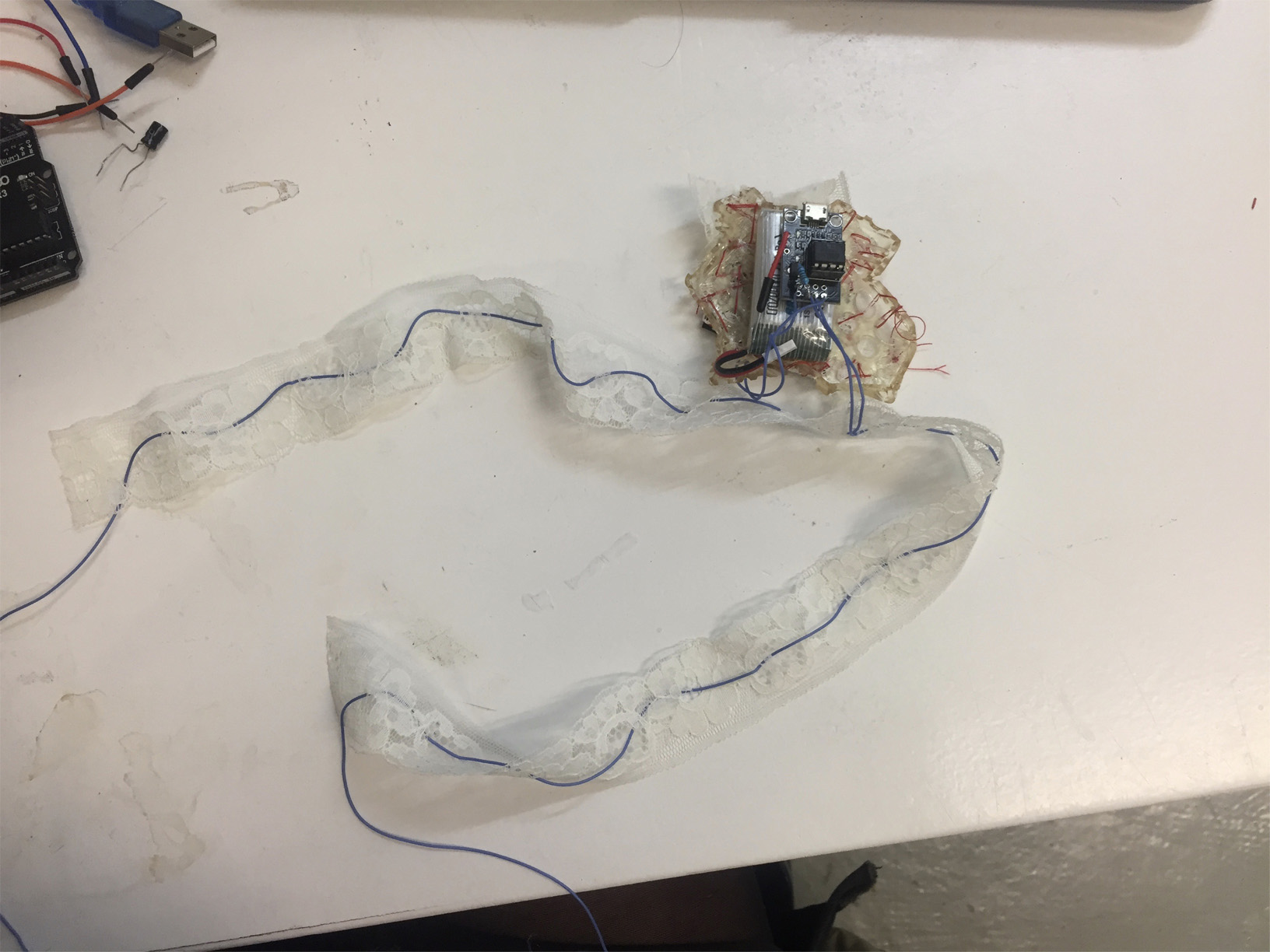
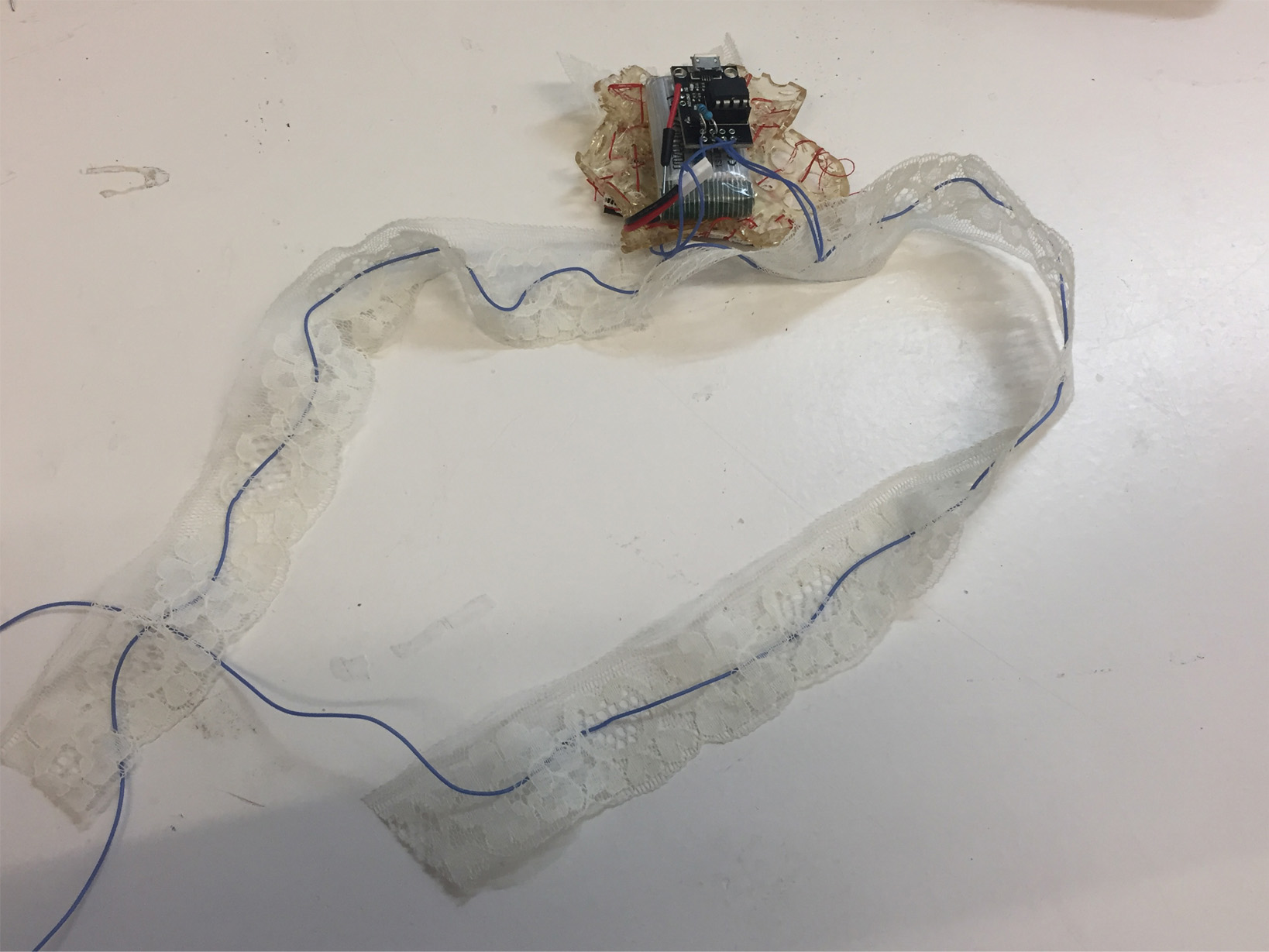
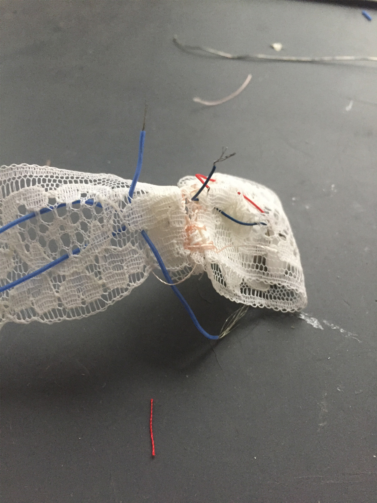
final piece