07 computational couture
2nd - 9th November 2021
7. Computational Couture
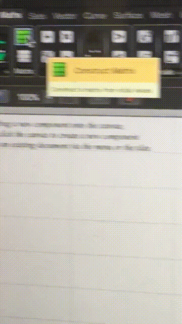
Learning Grasshopper this week is not just like learning a new language, but a new mindset towards design. Each design step is broken down into components: functions, generators, equations, formulas. Grasshopper maps each design step so that you can control the workflow and accuracy of your ideas. It's a really smart way to visually program details..
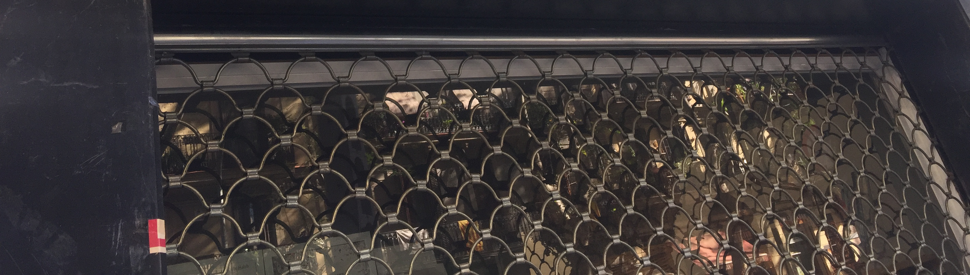
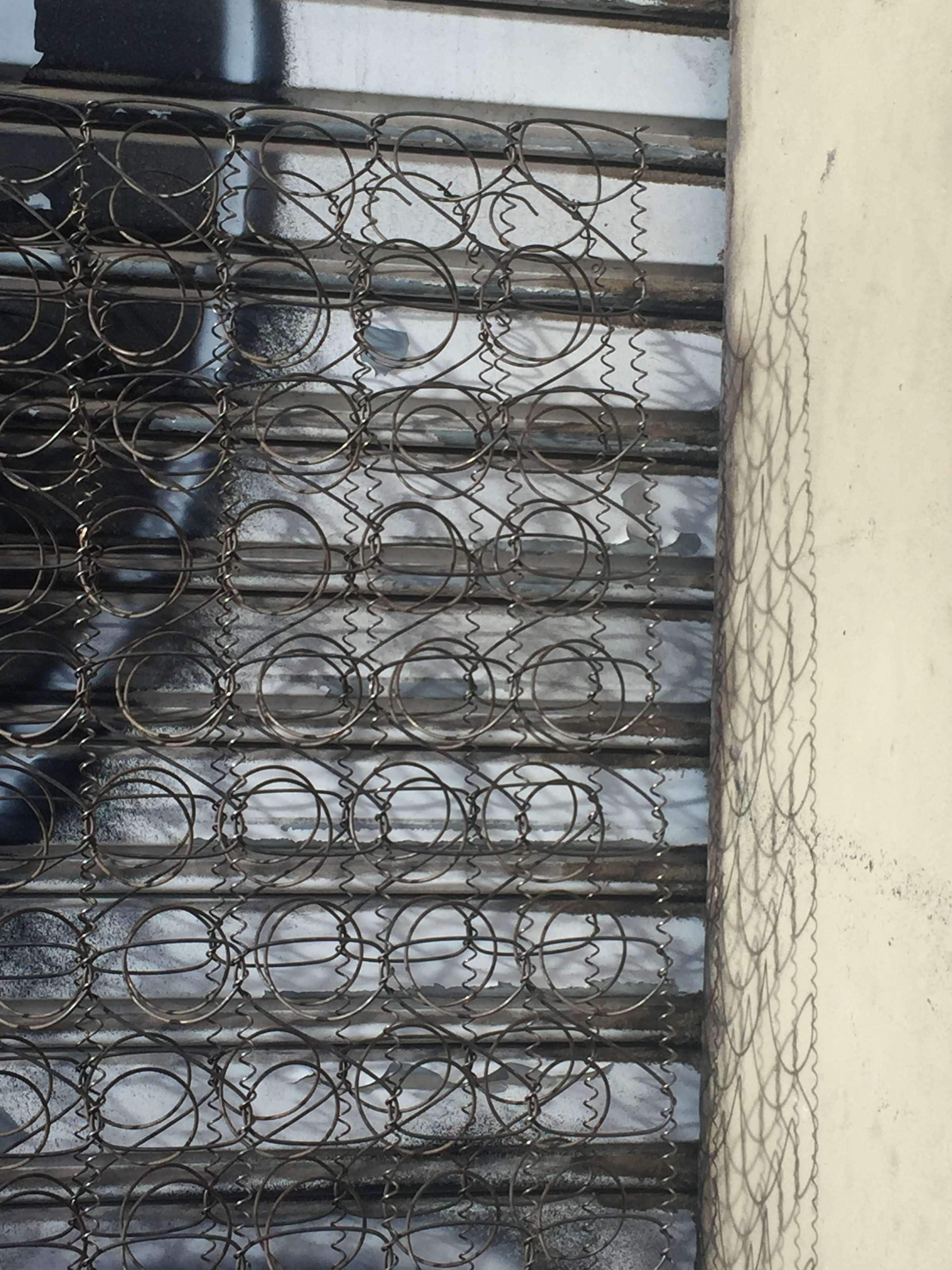
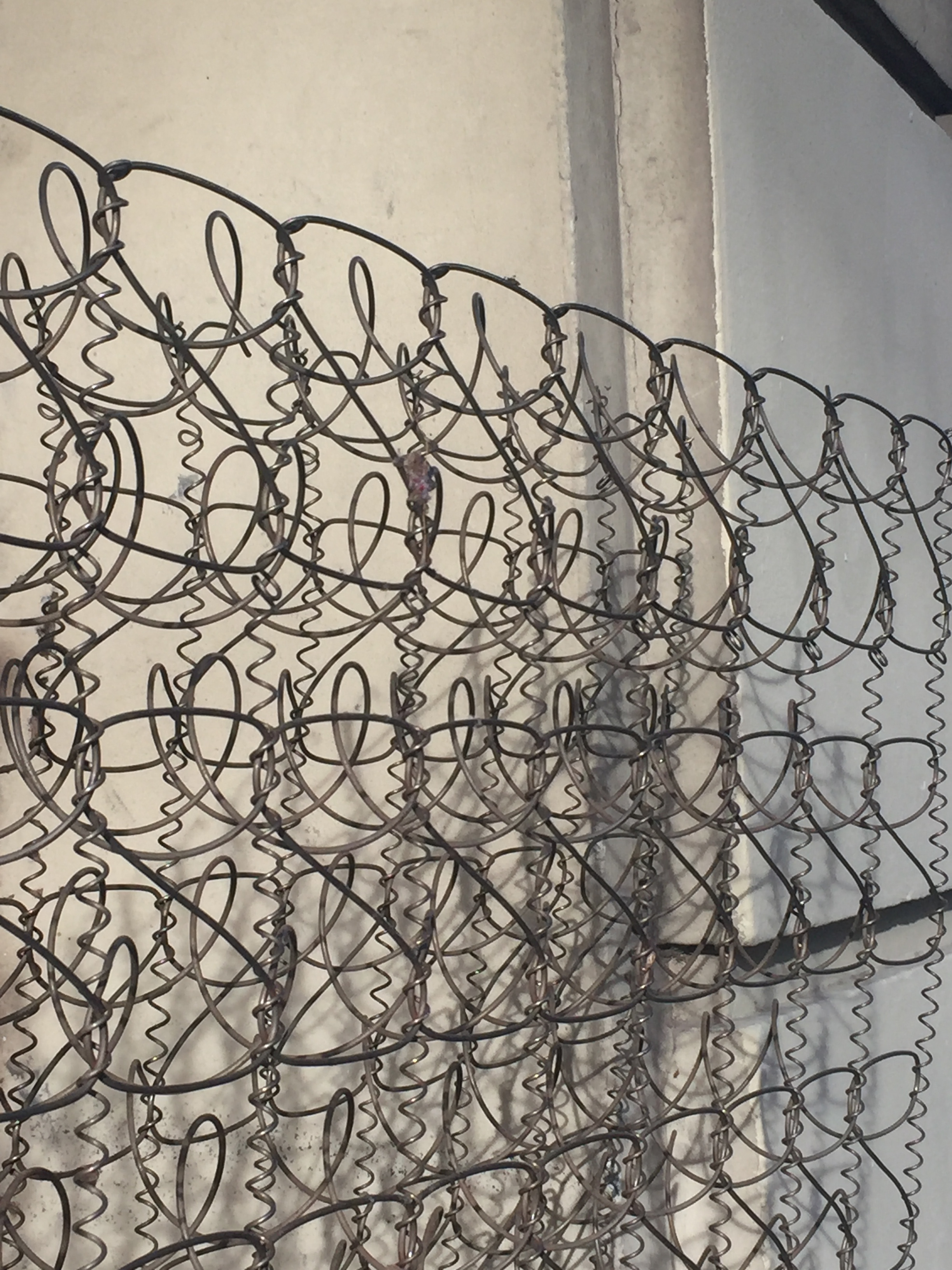
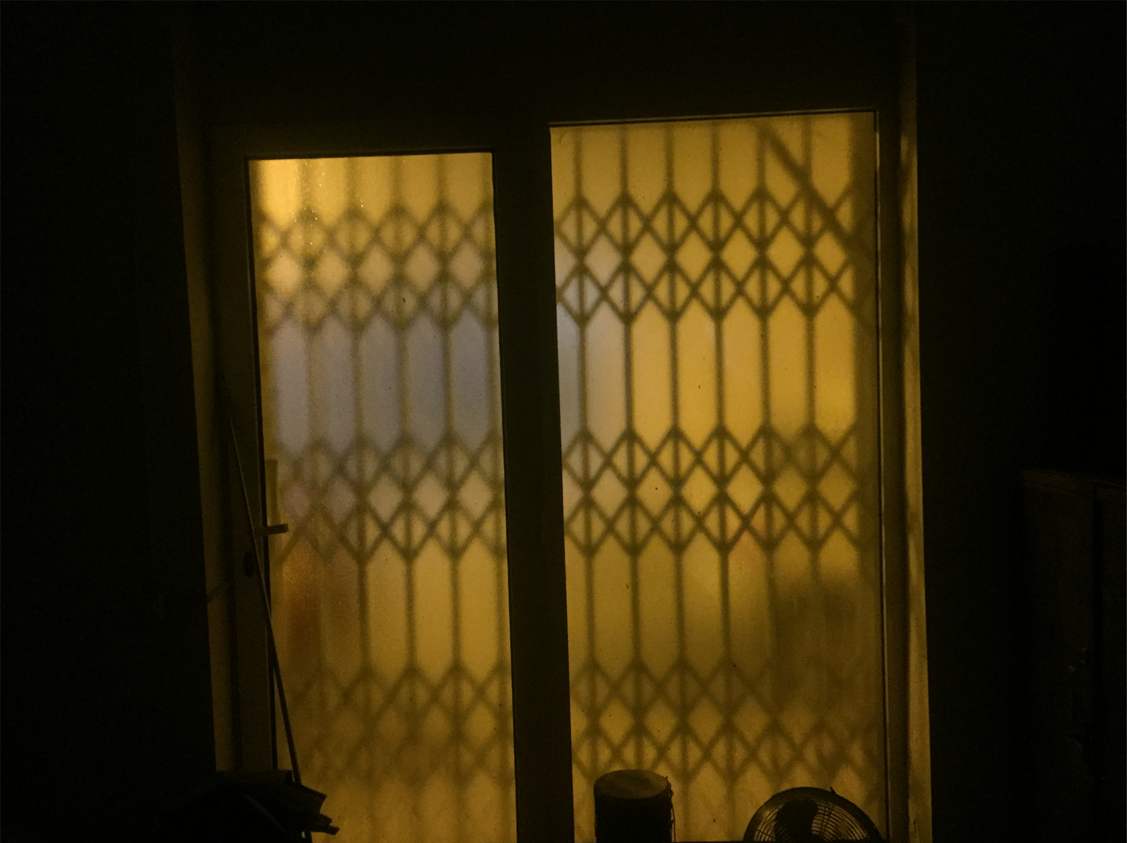
Here's some of my own inspiration for mesh shapes I want to try and create for this assignment:

3d printer intro
Some basics about using the 3D printers:
- PLA machines: Polylactic Acid
- all fillers are plastic based
- filaments are melted as they print
- standard nozzle size = 0.4mm
- heatlock cube
- bowden A Bowden extruder is a type of filament feeding mechanism used in many FDM 3d printers
- 2x fans on machine - cools down filament after melting
- compressor onto surface
- maximum 50% in fill
- 3 axis: x,y,z
- softer flexible filaments take longer
- print walls first
- wall thickness in shell always relates to nozzle size
- support = a structured piece that is removed from an isolated part of a design
- parameters: print settings profiles = layer thickness infill (strenghth) 50% (enough as standard)
- entraction = holding delay of filament over gaps in design (enable)
- do not export open objects
- z offset position and pressure of nozzle to not impact stroke size on fabric
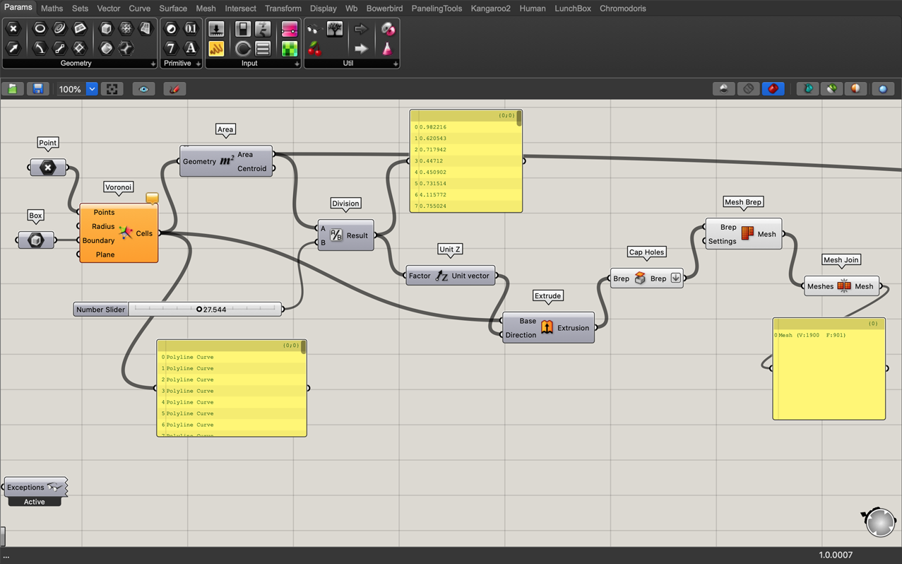
voronoi i
I started with following a short tutorial using the Voronoi algorithm to ease into using Grasshopper.
"Voronoi is a formulated diagram showing a partion of a plane, splitting regions depending on the mathematical positioning of points"
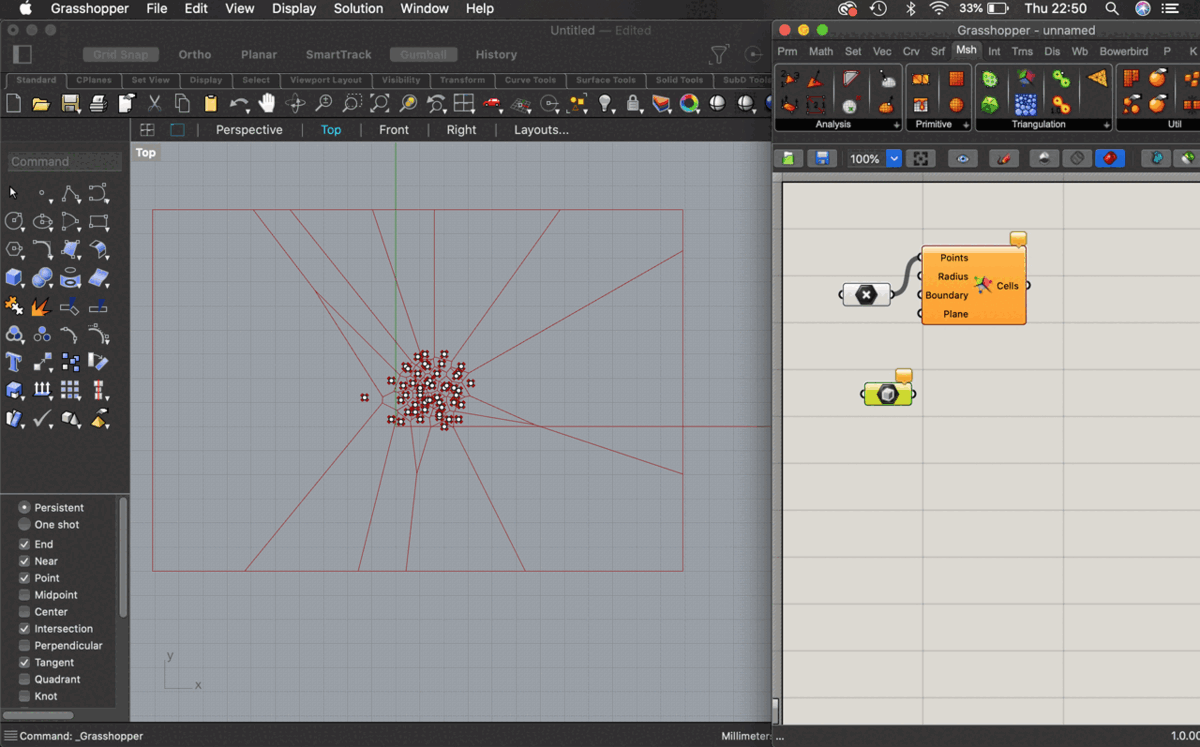
- Add multiple points to a Rhino canvas and open in Grasshopper
- Add points, box and Voronoi components
- Right click, add multiple points and select points to add to Grasshopper
- Add panel to cells output of Voronoi to see the available geometry from the drawn points
- Add area to cells output of Voronoi to calculate the area of the geometry output
- Add unit z (to give a command going in the direction of the Z axis) and..
- Divide the area by a value on a number slider by connecting division to unit z
- Connect extrusion Z axis output
- Add a brep (boundary representation object) and link to the extrusion to cap the holes in the extrusion
- Connect mesh brep to the brep
- Connect mesh join to mesh to complete the mesh
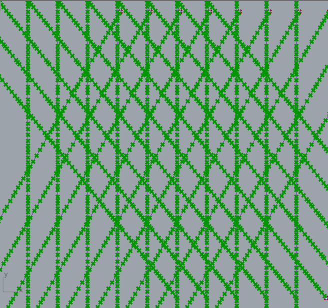
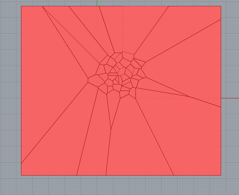
So the final mapping of the voronoi design looks like this...
and the geometry looks like this in Rhino after using Grasshopper...
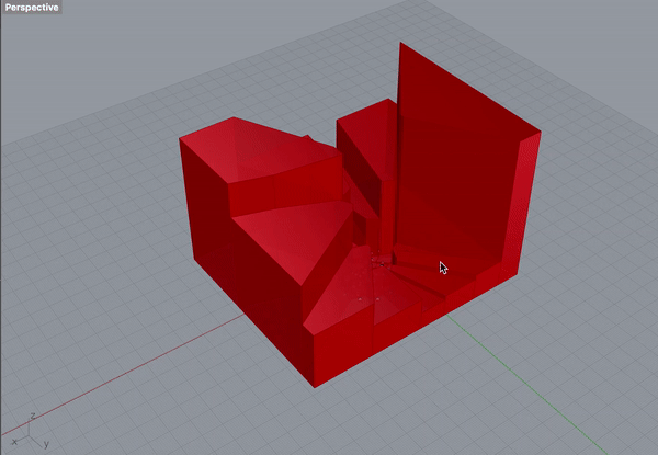
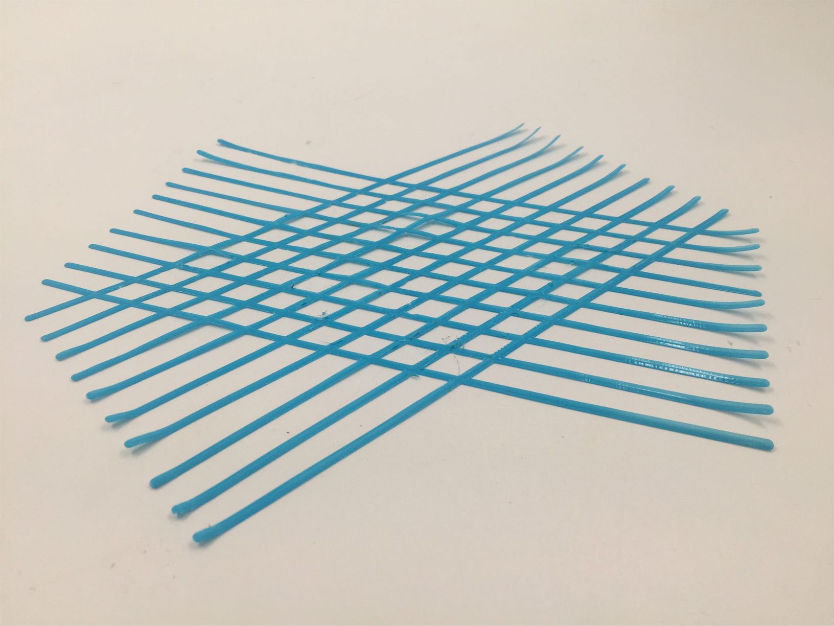
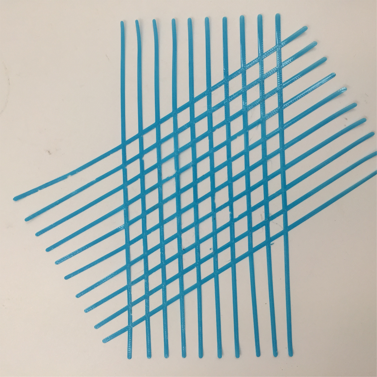
it would be cool to explore this more in another medium and to manipulate the structure some more.. for now the shapes will be too bulky to print onto fabric.
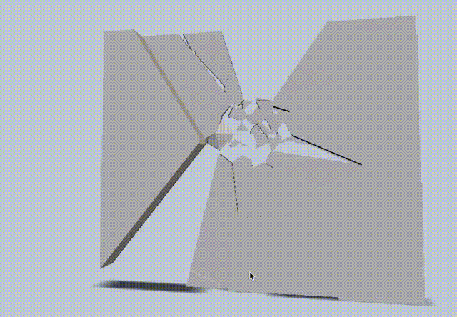
when i saved it as the STL file it doesn't look as thick and i like the fragments in the middle - but this will still be too bulky to print on fabric
voronoi ii
trying again with the voronoi as it is used in the computational couture tutorial
Fabricademy 20-21 Tutorials Grasshopper Part 1 from Fabricademy, Textile Academy on Vimeo.
- point, create relationship from drawing to outcome
- use transform move tool and link to point to create geometric transformation
- motion connection to unit x = motion being the space it will be moved in the x axis direction
- number slider to unit x factor = the number by which the point will be transformed = values min-max
- line command [line between 2 points] will generate a measured line from the original point by the parameters of the other commands
- using multiple points; selecting them and connecting them to poly line will make a line from the points
- point list will list points in order they appear
- the way you select points generate their order ie, one order or curve shape one way, and will change completely if selected differently
- linking interpolate command to points will generate curves from their ordered shape
- nurbs curve point does a similar command but offsets/staggers the curve drawn from the points
- you can connect 2 generated styles of curves to the curve program by holding shift to connect them
- boundary surface will transform a series of curves into a surface
- populate geometry command allows you to plot points inside geometry
- number of points generated by that command depends on count input so therefore you need a number slider to determine how many that will be
- seed input in populate geometry will shuffle the
- voronoi calculates the space where the points are centred
- bounding box to boundary surfaces will enclose the working surfaces
- connecting bounding box to voronoi boundary input will act as a trimmer
- bake will take everything from grasshopper and send it back to rhino
- surface split can be used to cut the new surface shapes generated by voronoi
- brep to evaluate surfaces; comparing area and surfaces
- using panels to collect values from brep and split surfaces: decide to separate values smaller or larger than a value on the number slider
- dispatch to separate true from false (list to dispatch is from fragment list)
- from dispatching to surface to offset curve to negotiate the sizing of the offsets in each cut surface: use a slider to determine the negative values for it
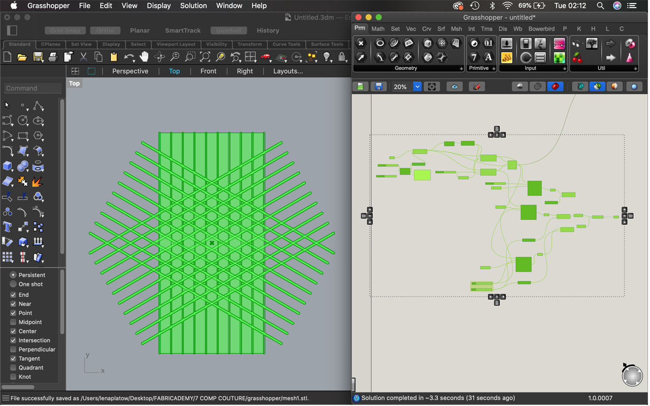
making a mesh
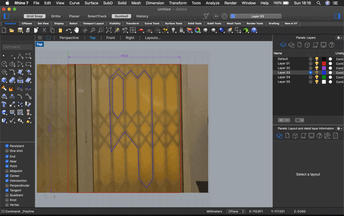
Making a mesh based on my photo
- Starting with bringing the photo into Rhino using the picture command
- Opening Grasshopper, adding a curve command and selecting multiple curves
- Connect to Project
- Connect to Curve to polyline and draw out a number slider
- Add From curve to polyline output, connect polyline to BB offset
- From BB offset draw an XY plane from the plane input and a number slider
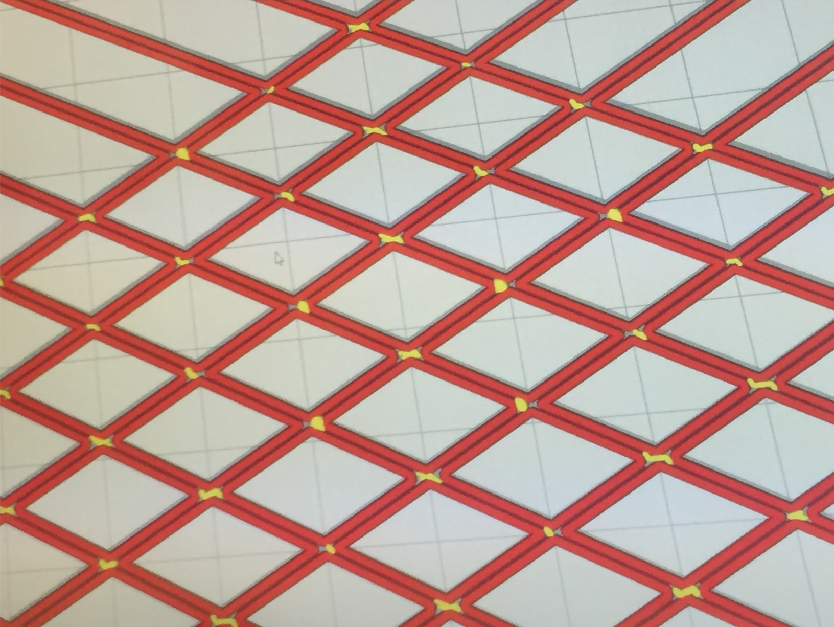
so the curves are transformed into geometry by the curve to polyline and offset by the value of the number slider in the direction of the plane I remade the mesh in this way:
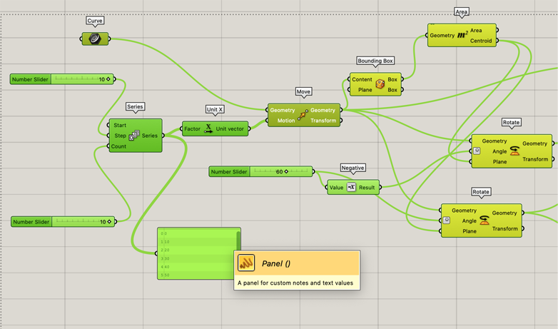
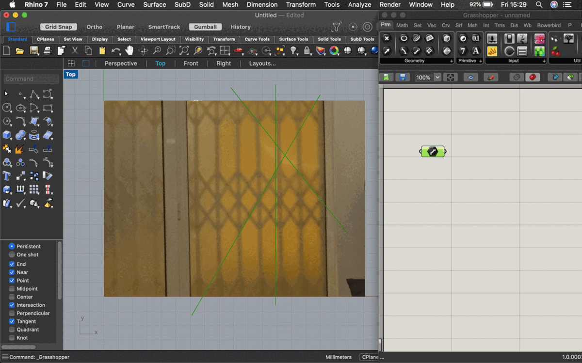
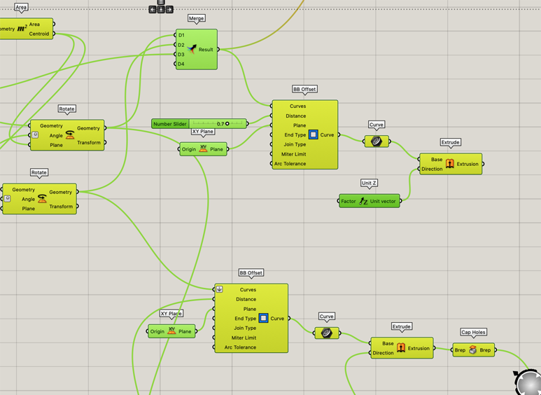
Starting with the curve function; using move to move and copy it in the direction of unit x; 10 times with the number slider
Connecting a bounding box to the geometry output of the move component; the area is generated from this output; combined with the outputs of move and connected to 2 different rotate components (the angle of rotations are generated with negative component rotating 60 degrees)

extra tutorials
Here are some other tutorials I found helpful:
Grasshopper Tutorial - Folded Plate Structure from WALLACE on Vimeo.
Tri panel system with Grasshopper from Rhino Tutorials on Vimeo.
Designing 3D Patterns with Rhino and Grasshopper from Novedge on Vimeo.
https://vimeo.com/52927770