8. Wearables
Research and inspiration
My research was focused on flexinol, shape memory alloys where I wanted to work with some kind of soft motion. From the tutorials of the week i learned that wearables can be used to protect, express or communicate information. Arduino or ATtiny is used as a programming for actuators(circuits) to work in a sertain way. An actuator is a device that produces a motion by converting energy and signals going into the system, it can be visual, sound, vibration and so on. This week I ended up working mostly with nitinol that was very think and not suitible for textiles samples but fun to work with, and mini vibrators.
I had bought nitinol I found online to use this week for the TextileLab, thinking it was the right component but it was to thick, 1 mm, so for next time I would buy a thinner flexinol But I would really like to try that. But flexinol or nitinol are shape memory alloys that can be trained to remember sertain shapes when heated even though they are bent in other ways. The temperature can vary from body temperature to 50°c from what I have looked at
 nr 2: Drapery FM
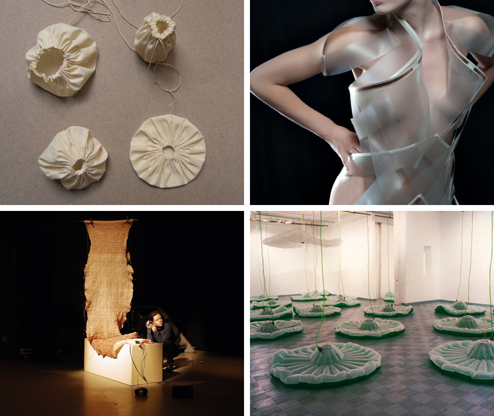
Drapery FM consists of a knitted piece of fabric that can electronically communicate the story of how it has been made to and through the surrounding radio receivers. The piece of fabric is essentially a micro FM transmitter that is, for the most part, made from copper wire and wool. Tuned into the right radio frequency, radios within the transmission range of this fabric receive and play out the sound recordings made during its production.
nr 3: Intimacy White
Intimacy, developed by Studio Roosegaarde and V2_Lab, is a project that connects the world of fashion, wearables and electronic arts. It explores the relation between technology and intimacy in contemporary tech-society.
nr 4: Lee Boroson / Pleasure Grounds / 1999 Inflated installation.
nr 2: Drapery FM
Drapery FM consists of a knitted piece of fabric that can electronically communicate the story of how it has been made to and through the surrounding radio receivers. The piece of fabric is essentially a micro FM transmitter that is, for the most part, made from copper wire and wool. Tuned into the right radio frequency, radios within the transmission range of this fabric receive and play out the sound recordings made during its production.
nr 3: Intimacy White
Intimacy, developed by Studio Roosegaarde and V2_Lab, is a project that connects the world of fashion, wearables and electronic arts. It explores the relation between technology and intimacy in contemporary tech-society.
nr 4: Lee Boroson / Pleasure Grounds / 1999 Inflated installation.
felted landscapes https://newtextiles.media.mit.edu/index.html%3Fp=3120.html https://pin.it/W5yohNo
Motion
Flexinol from Liza Stark on Vimeo.
Remember: More power doesn't make the movement more dramatic, just change the shape more quickly. You will want to make sure you give the wire time to breathe and relax. This way the next contraction will be more dramatic.
Shape Changing Textile Technical Characteristics of FLEXINOL motion
Tools
- [slides](https://docs.google.com/presentation/d/1s_StEoFFkxUgGzaQmpCSZWH_IqyVzPo7st1fMzgCEDg/view#slide=id.g47e1f03d3f_1_1233)
Flipdot time
Tools
- wire
- magnet
- 9v battery
- aligator clips
Flexinol fabric tests
Tools
- Nitinol
- camping cas stove
- mold
- fabric
- 9v battery
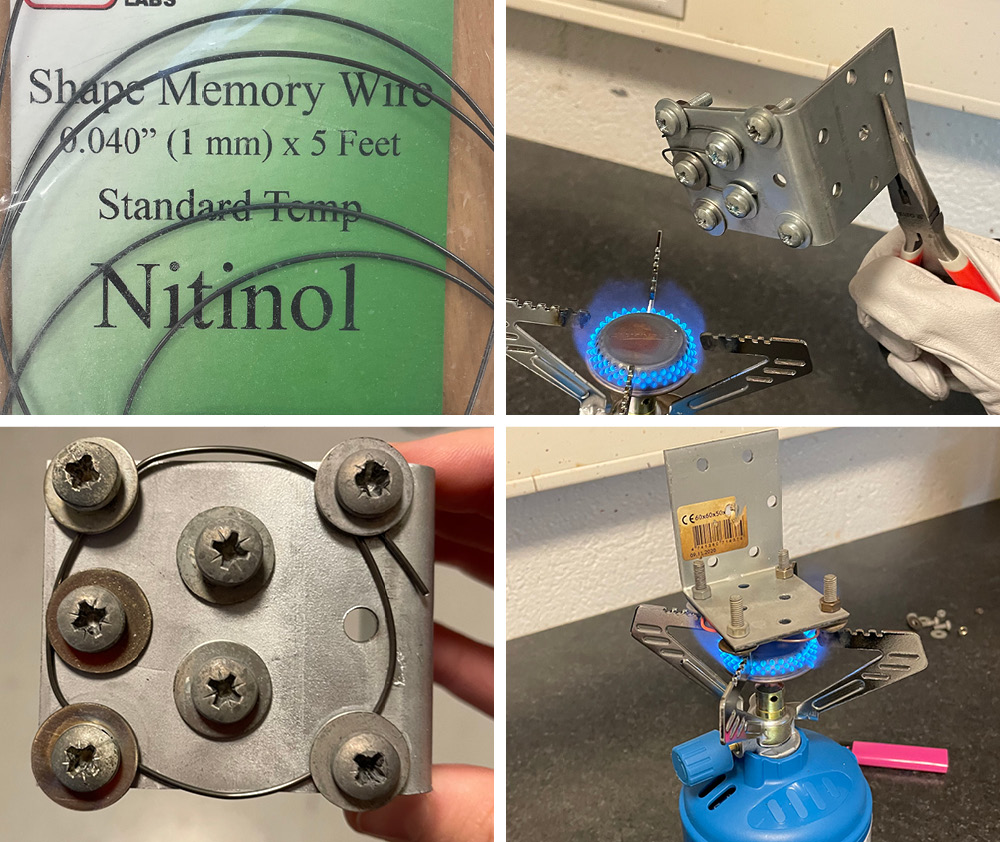 For Shape memory alloys to change shape you need to train the wire to a desired shape before embeding it to fabric. To do so you need to make a mold to shape the wire on and then heat it up to 500°c for 1-2 minutes. Then cool it down fast.
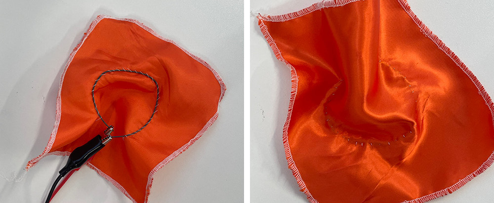 I tried activating the nitino tests with 9v battery but then moved on to the thing and gave it more volts for more activeness. unfortunatly the wire never went to its original shape again so there was nood to try to work with it in arduino.
Neopixels
Tools
- Adafruit NEOpixel stick x5050 RGB LED
- conductive thread
- solduring iron
- fabric
Code Example for Neopixels
After the tutorial with Emma I noticed the Neopixel effect generator I think I would work more on that if I had more time in the future! To remember the arduino and Neopixel setup I put it also up in Tinkercad, Party led switch from blue/magenta with the code.
![]()
But for this code I started by downloading the Adafruit Neopixel library and installing it on the Arduino software.
/*
 * Emma Pareschi
 *
 * Basic commands of Library Adafruit_NeoPixel
 * Using some parts from the example "strandtest"
 */

#include <Adafruit_NeoPixel.h>

// Which pin on the Arduino is connected to the NeoPixels?
#define PIN            6

// How many NeoPixels are attached to the Arduino?
#define NUMPIXELS      8


// Declare our NeoPixel pixels object:
Adafruit_NeoPixel pixels = Adafruit_NeoPixel(NUMPIXELS, PIN, NEO_GRB + NEO_KHZ800);
// Argument 1 = Number of pixels in NeoPixel strip
// Argument 2 = Arduino pin number (most are valid)
// Argument 3 = Pixel type flags, add together as needed:
//   NEO_KHZ800  800 KHz bitstream (most NeoPixel products w/WS2812 LEDs)
//   NEO_KHZ400  400 KHz (classic 'v1' (not v2) FLORA pixels, WS2811 drivers)
//   NEO_GRB     Pixels are wired for GRB bitstream (most NeoPixel products)
//   NEO_RGB     Pixels are wired for RGB bitstream (v1 FLORA pixels, not v2)
//   NEO_RGBW    Pixels are wired for RGBW bitstream (NeoPixel RGBW products)


//pack the color in one variable
uint32_t red = pixels.Color(255, 0, 0); //RGB
uint32_t blue = pixels.Color(0, 0, 255);
uint32_t green = pixels.Color(0, 255, 0);
uint32_t magenta = pixels.Color(255, 0, 255);
uint32_t off = pixels.Color(0, 0, 0);

int delayval = 500; // delay for half a second

void setup() {

  pixels.begin(); // This initializes the NeoPixel library.
  pixels.show();            // Turn OFF all pixels ASAP
  pixels.setBrightness(20); //from 0 to 255, use it only in setup

}

void loop() {

  pixels.setPixelColor(0, magenta); //set the color red on the first pixel
  pixels.setPixelColor(1, blue);
  pixels.setPixelColor(2, magenta);
  pixels.setPixelColor(3, blue);
  pixels.setPixelColor(4, magenta);
  pixels.setPixelColor(5, blue);
  pixels.setPixelColor(6, magenta);
  pixels.setPixelColor(7, blue);
  pixels.show();  //display the color
  delay(delayval);

  pixels.setPixelColor(0, blue); //set the color green on the first pixel
  pixels.setPixelColor(1, magenta);
  pixels.setPixelColor(2, blue);
  pixels.setPixelColor(3, magenta);
  pixels.setPixelColor(4, blue);
  pixels.setPixelColor(5, magenta);
  pixels.setPixelColor(6, blue);
  pixels.setPixelColor(7, magenta);

  pixels.show();  //display the color
  delay(delayval);

  //pixels.setPixelColor(0, off); //set the color green
  //pixels.show();  //display the color
  //delay(delayval);

}
Mini vibrator fabric tests
Mini vibrator motors are tiny discs, completely sealed up so they're easy to use and embed. They have Two wires are used to control/power the vibration. The rated voltage is 2.5 to 3.8V and for many projects and vibrates from 2V up to 5V, higher voltages result in more current draw but also a stronger vibration, an they are similar to vibrators used in phones for buzzing.
Tools
- mini motors 3v
- 3v battery
- fabric
- aligator clips
Code Example for minivibrators
Me and Alberte worked on a few different codes when we were trying out the possibilites working with mini vibration motors. We started out with the blink code using one vibrator, The code is used to control LED light but it also worked for the vibration motor! I think it was because we still put the digital pin to 13.
Blink code
/*
  Blink

  Turns an LED on for one second, then off for one second, repeatedly.

  Most Arduinos have an on-board LED you can control. On the UNO, MEGA and ZERO
  it is attached to digital pin 13, on MKR1000 on pin 6. LED_BUILTIN is set to
  the correct LED pin independent of which board is used.
  If you want to know what pin the on-board LED is connected to on your Arduino
  model, check the Technical Specs of your board at:
  https://www.arduino.cc/en/Main/Products

  modified 8 May 2014
  by Scott Fitzgerald
  modified 2 Sep 2016
  by Arturo Guadalupi
  modified 8 Sep 2016
  by Colby Newman

  This example code is in the public domain.

  https://www.arduino.cc/en/Tutorial/BuiltInExamples/Blink
*/

// the setup function runs once when you press reset or power the board
void setup() {
  // initialize digital pin LED_BUILTIN as an output.
  pinMode(LED_BUILTIN, OUTPUT);
}

// the loop function runs over and over again forever
void loop() {
  digitalWrite(LED_BUILTIN, HIGH);  // turn the LED on (HIGH is the voltage level)
  delay(1000);                      // wait for a second
  digitalWrite(LED_BUILTIN, LOW);   // turn the LED off by making the voltage LOW
  delay(1000);                      // wait for a second
}

Altering the vibration

// the loop function runs over and over again forever
void loop() {
  digitalWrite(LED_BUILTIN, HIGH);  // turn the LED on (HIGH is the voltage level)
  delay(500);                      // wait for a second
  digitalWrite(LED_BUILTIN, LOW);   // turn the LED off by making the voltage LOW
  delay(500);                      // wait for a second
}

Altering the vibration

// the loop function runs over and over again forever
void loop() {
  digitalWrite(LED_BUILTIN, HIGH);  // turn the LED on (HIGH is the voltage level)
  delay(2000);                      // wait for a second
  digitalWrite(LED_BUILTIN, LOW);   // turn the LED off by making the voltage LOW
  delay(2000);                      // wait for a second
}

Altering the vibration

// the loop function runs over and over again forever
void loop() {
  digitalWrite(LED_BUILTIN, HIGH);  // turn the LED on (HIGH is the voltage level)
  delay(2000);                      // wait for a second
  digitalWrite(LED_BUILTIN, LOW);   // turn the LED off by making the voltage LOW
  delay(500);                      // wait for a second
}
Altering the vibration

// the loop function runs over and over again forever
void loop() {
  digitalWrite(LED_BUILTIN, HIGH);  // turn the LED on (HIGH is the voltage level)
  delay(500);                      // wait for a second
  digitalWrite(LED_BUILTIN, LOW);   // turn the LED off by making the voltage LOW
  delay(2000);                      // wait for a second
}
Two motor blink code
Here we added a second motor which worked well, You can see the results in the video below, but we played with putting different speed and delays on each motor. The motor can go really fast!
/*
  Blink

  Turns an LED on for one second, then off for one second, repeatedly.

  Most Arduinos have an on-board LED you can control. On the UNO, MEGA and ZERO
  it is attached to digital pin 13, on MKR1000 on pin 6. LED_BUILTIN is set to
  the correct LED pin independent of which board is used.
  If you want to know what pin the on-board LED is connected to on your Arduino
  model, check the Technical Specs of your board at:
  https://www.arduino.cc/en/Main/Products

  modified 8 May 2014
  by Scott Fitzgerald
  modified 2 Sep 2016
  by Arturo Guadalupi
  modified 8 Sep 2016
  by Colby Newman

  This example code is in the public domain.

  https://www.arduino.cc/en/Tutorial/BuiltInExamples/Blink
*/
int motor1=9;
int motor2=10;

// the setup function runs once when you press reset or power the board
void setup() {
  // initialize digital pin LED_BUILTIN as an output.
  pinMode(motor1, OUTPUT);
  pinMode(motor2, OUTPUT);
}

// the loop function runs over and over again forever
void loop() {
  digitalWrite(motor1, HIGH);  // turn the LED on (HIGH is the voltage level)
  delay(2000);
  digitalWrite(motor2, HIGH);  // turn the LED on (HIGH is the voltage level)
  delay(500);                      // wait for a second
  digitalWrite(motor1, LOW);   // turn the LED off by making the voltage LOW
  delay(2000);
  digitalWrite(motor2, LOW);   // turn the LED off by making the voltage LOW
  delay(500);  // wait for a second

}
Analog sensor first and failed test
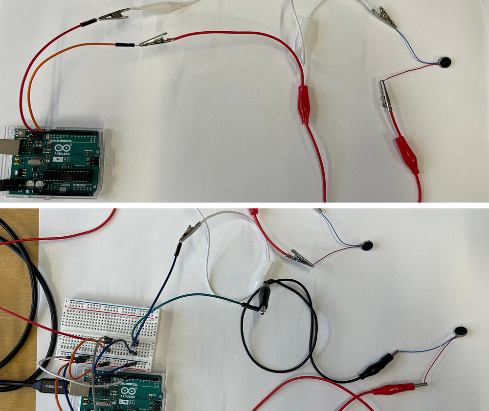
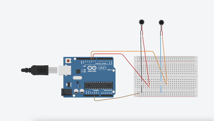
Since our first two tries worked out so well we wanted to see if we could add analog sensor er the input for the vibartion motors. We connected the sample we made in the week of textile electronics, but somehow it would not read the pressure sensor. We decided that is was enough for one day and we should start focusing on how we could impliment the vibartion motor into a fabric test. If I would try again I could use this refrenence from Louise!
*
  Smoothing

  Reads repeatedly from an analog input, calculating a running average and
  printing it to the computer. Keeps ten readings in an array and continually
  averages them.

  The circuit:
  - analog sensor (potentiometer will do) attached to analog input 0

  created 22 Apr 2007
  by David A. Mellis  <dam@mellis.org>
  modified 9 Apr 2012
  by Tom Igoe

  This example code is in the public domain.

  https://www.arduino.cc/en/Tutorial/BuiltInExamples/Smoothing
*/

// Define the number of samples to keep track of. The higher the number, the
// more the readings will be smoothed, but the slower the output will respond to
// the input. Using a constant rather than a normal variable lets us use this
// value to determine the size of the readings array.
const int numReadings = 10;

int readings[numReadings];      // the readings from the analog input
int readIndex = 0;              // the index of the current reading
int total = 0;                  // the running total
int average = 0;                // the average

int inputPin = A0;
int led_pin = 3; //change the pin of the Led

void setup() {
  // initialize serial communication with computer:
  Serial.begin(9600);
  // initialize all the readings to 0:
  for (int thisReading = 0; thisReading < numReadings; thisReading++) {
    readings[thisReading] = 0;
  }

    pinMode(led_pin, OUTPUT);   //initialize led pin
}

void loop() {
  // subtract the last reading:
  total = total - readings[readIndex];
  // read from the sensor:
  readings[readIndex] = analogRead(inputPin);
  // add the reading to the total:
  total = total + readings[readIndex];
  // advance to the next position in the array:
  readIndex = readIndex + 1;

  // if we're at the end of the array...
  if (readIndex >= numReadings) {
    // ...wrap around to the beginning:
    readIndex = 0;
  }

  // calculate the average:
  average = total / numReadings;


  // send it to the computer as ASCII digits
  Serial.println(average);
  average = map(average, 60, 230, 0, 255); //we change the range
  average = constrain(average, 0, 255); //we apply the limits

  delay(50);        // delay in between reads for stability
  analogWrite(led_pin, average);
}
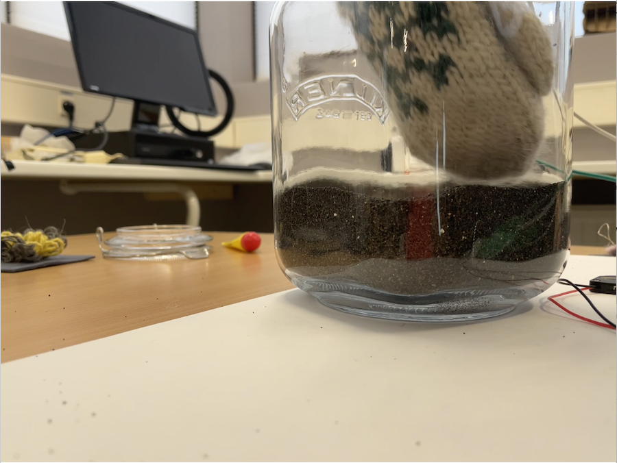
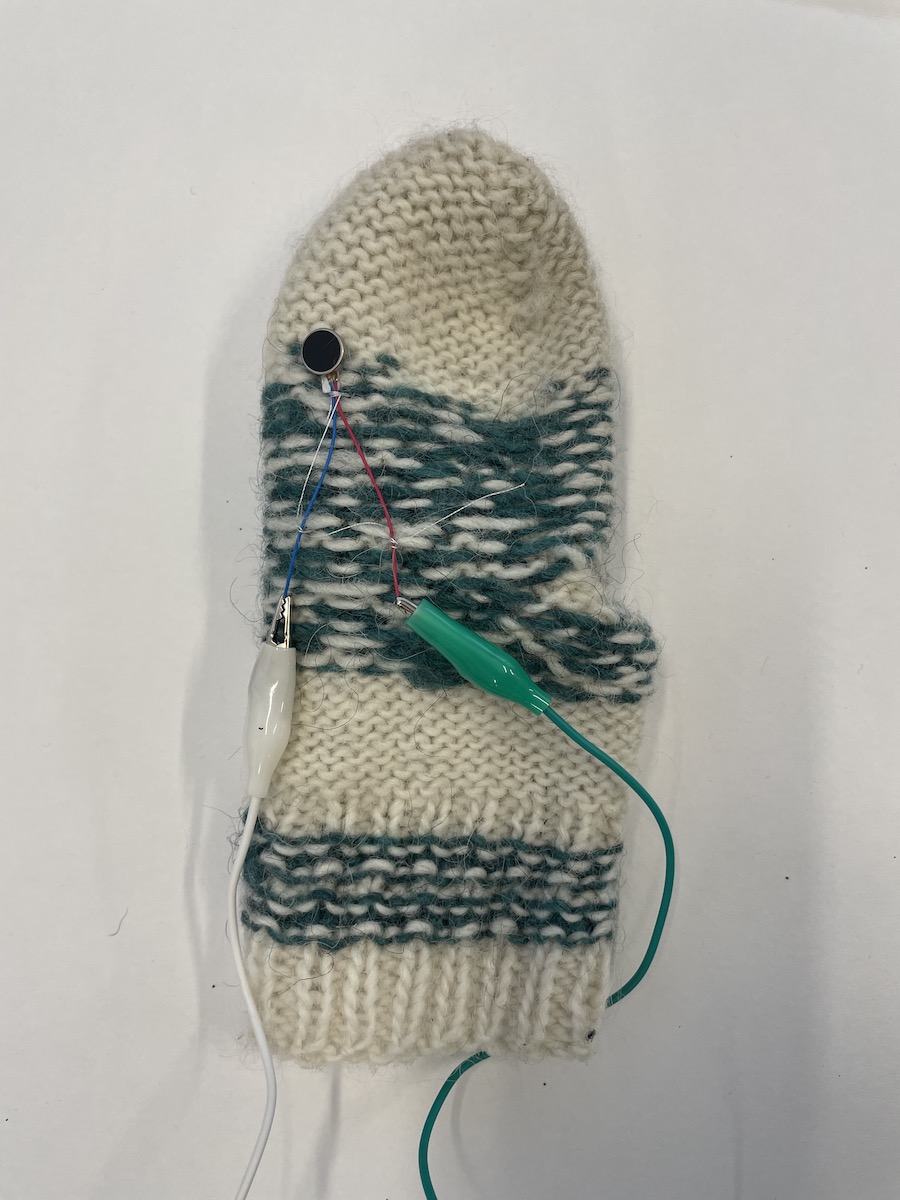
My first thought when starting to work with the vibration motor was to shake something off of yourself, like snow, rain, or sand. That feeling of wanted to get rid of something and the best way is to shake it instead of dusting something off, especially the snow! I sometimes babysit my sisters kids and they always bring so much sand in with their clothes after playing around on the beach too. So I went to the beach and collected some sand. Then I implimented the vibratoir into the glove I usually wear and did some tests with dipping my hand into the sand to see if the sand would shake of with the vibration. The test did not really work due to the motor not being strong enough for the shaking of the glove and the gloce not caching enough sand.
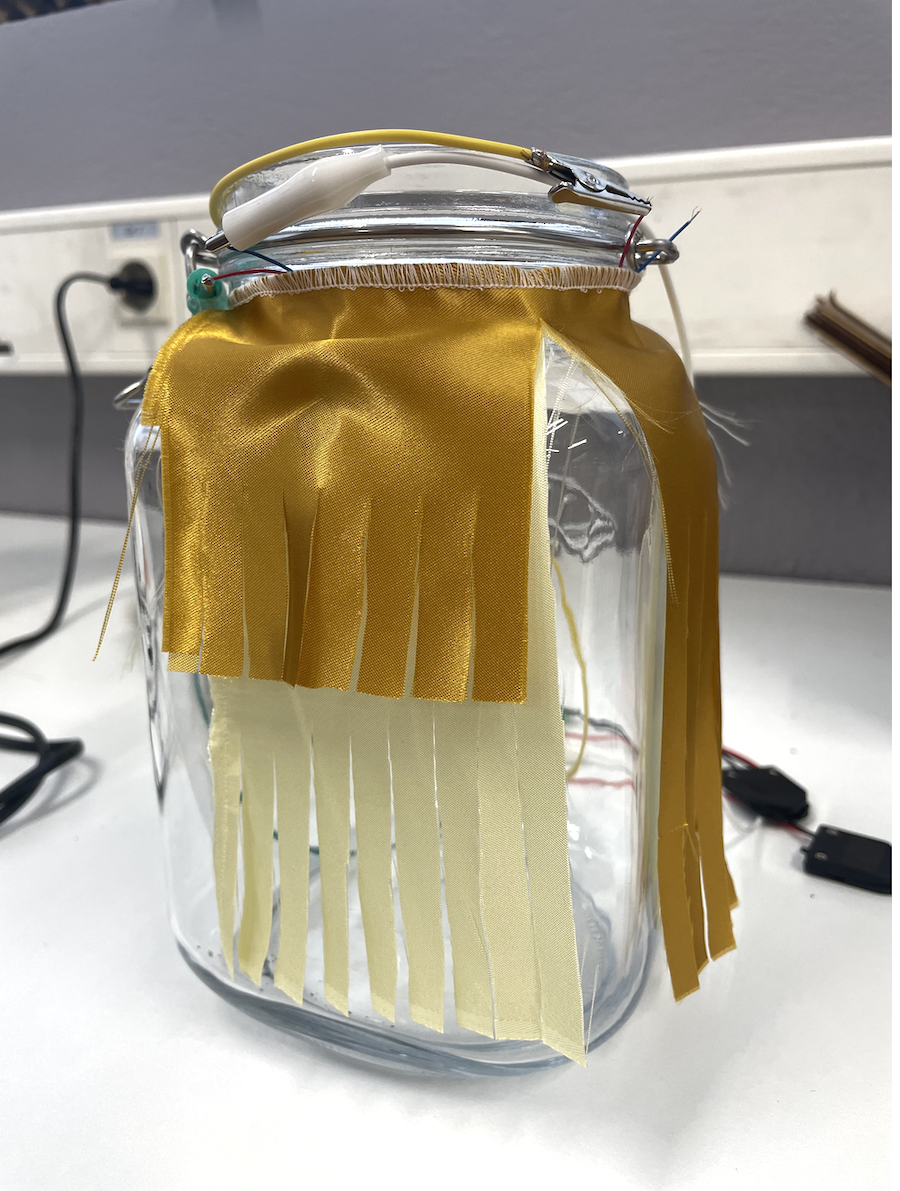 I did not give up though and worked instead with fringes from a beautiful silk like material. It was good to work with the motor and material also to understand the limits and how it could work. I did not end up with a big piece for this week but I am happy with my experiments.
My tests were kind of in the feeling of this dog
Here are is the results from all of the experiments done with the vibration motor