5. E-textiles
Introduction
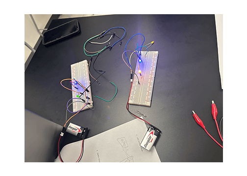
In my Neuroscience class, students are learning about how neurons communicate to each other to form a neural circuit. I use circuits to compare to how the nervous system works and also to bring a hands-on component to the course. Students are currently learning how to breadboard, starting with building simple LED circuits (as shown in image). After gettting familiar with the basics of circuitry, students will then learn how ot program Arduino to ultimately build an artifical neural network. This neural network has an input layer that responds to light (photoresistors), sends signals to the processing layer and finally to the output layer to turn on or off LEDs.
I am really excited to advance my knowledge of circuitry in order to bring in more projects for my students as well as my own personal use. Taking inspiration from my neuroscience class, my goal is to create an interactive neuron in this project. I would like the dendrites (input) of the neuron to respond to touch. The touch stimulus will then produce an action potential in the axon visualized through a sequence of LEDs. I am trying to think about how to visualize the release of neurotransmitters. So far I think maybe using thermochromic paint. I'm hoping the effect of the thermochromic paint will mimic the slower release of chemical signal compared to the fast electrical signal of the action potential.
Inspiration

I am grateful to have had the opportunity to meet my Fabricademy mentor, Nuria Robles Miguélez, at UCLA... even if it was only for 15 minutes! She gave me an e-textile student kit from FabLab Leon and I have described that kit below. Here's a picture of us meeting!
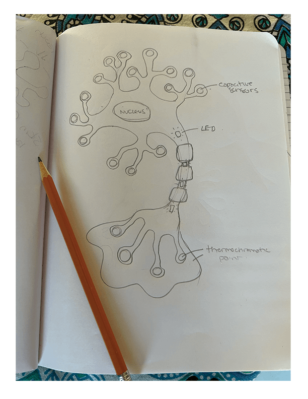
Figure 1. Sketch of the concept. I sketched out the basic shape of a neuron. The dendrites would each be a capacitive sensor. The sensor would stimulate the LEDs running down the axon. The thermochromic paint would be painted at the ends of the axon terminals and also in the synapse.
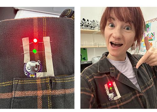
Figure 2. I made a parallel LED circuit on my shirt during the Thursday tutorial. Success! I used conductive cloth adhesion tape as the conductive material. I wore this the whole day while teaching! The students thought I had a heart monitor on haha
Results
Velostat
What is velostat? Velostat is a type of electrically conductive material that exhibits variable resistance based on the amount of pressure applied to it. When pressure is applied to the velostat, its resistance decreases. The addition of velostat into a circuit to create pressure-sensitive switches such as turning on or off an LED.
In the e-textile kit shown below, velostat is used as a pressure-sensitive switch to turn on and off an LED.
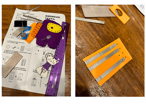
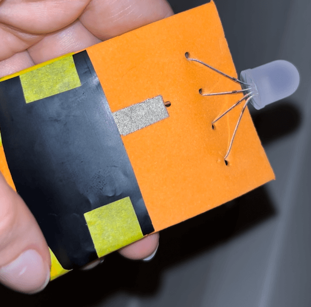
Figure 1. E-textile Gift from FabLab Leon I was so excited to build this cute Among Us character that I spent my birthday evening making it! The instructions were very easy to follow visually. I think this is such a cool way to introduce young people to the world of electronics. It inspired me to think about ways I might build off of this concept in my own work with students.
Video. Completed Among Us character Completed velostat/LED circuit student kit from FabLab Leon, courtesy of Nuria.
Thermochromic circuit
To make an electrochromatic circuit, I used Kobakant's In All Different Colors instructions. I mixed thermochromic pigment with screen-printing transparent base. I painted the mix on a piece of cotton. I then sewed a few stitches of stainless steel thread into the sotton. I attached both ends of the thread to a 3V battery. The thread itself has a resistance of 10 Ohms per foot. Because of this low resistance, heat is generated along the thread, heating it and ultimately changing the thermochromic paint from black to pink. I also found that this pigment itself is conductive using the multimeter.
Capacitive Sensor

Figure 1. First time soldering I used the Adafruit 12-Key Capacitive Touch Sensor breakout board. I learned how to solder to add the header strip to the breakout board. I somehow messed up the connections on the first sensor but luckily I had an extra so I tried again on that and it worked. I'll have to go back to figure out what I did wrong on the first one. I moved forward with the soldered breakout board and followed the instructions on Adafruit's site to test the sensor.
Testing the capacitive sensor
I then downloaded the Adafruit_MPR121 into my Arduino library and proceded to test the code. I opened the serial terminal window to show the touch detection. I then touched the sensor and it worked. Next, I wanted to test a proof of concept by attaching a steel thread onto one of the sensor inputs. At the end of the thread I attached a piece of conductive cloth adhesive tape. When I touched the tape the sensor still detected the signal!
Capacitive sensor with LEDS
I then went to ChatGPT to get some code to link up the capacitive sensor to the LEDs. ChatGPT was extremely helpful in getting the results I was hoping for. It even gave me instructions on how to set up the LEDs as shown in the methods and materials section below.
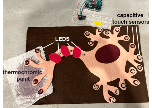
Figure 2. Putting it all together. This is still a WIP. But here I show the fabric that I am using (felt) and the general layout of the electronics. When you touch any of the dendrites, the conductive cloth adhesion tape is connected to the sensor with steel thread. The capacitive touch sensor detects the signal, initiating the Arduino code to activate the LEDs starting in the axon hillock. The LEDs blink on and off sequentially as the action potential moves down the axon into the axon terminals. The thermochromic paint will also be connected to the circuit and will begin to heat up throughout the whole process changing the color slowly representing the release of neurotransmitters.
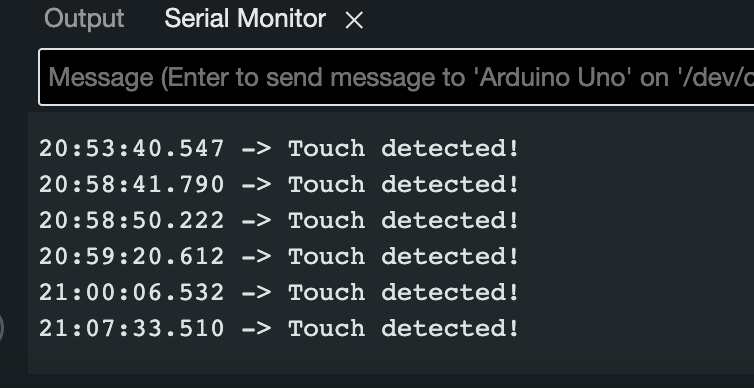
Figure 3. The Serial Monitor was used to observe the touch sensory data in real-time. When I touched the capacitive touch sensor, the serial monitor displays that sensory data. This is an image of the serial monitor after I had tested the capacitive touch sensor multiple times.
Completed Neuron with capacitive sensor
The end result of the e-textile neuron. The concept mostly came together as I had imagined it. However, the neuron does not have the thermochromic paint as I initially wanted but I think it works as a prototype if I want to revisit and refine this project later on.
Discussion
I feel pretty good about the end result of this project. I started with the idea of an interactive neuron and I was successful in that goal. Initially, I wanted to use both a capacitive sensor and thermochromic paint but in the end I decided to focus on completing the capacitive sensor. I reworked the thermochromic sensor in another swatch for the wearables week. The most challenging aspect of building the e-textile capacitive sensor swatch was trying to figure out if I should hide the circuit components or make certain parts visible. The conductive tape is straightforward to use but doens't look high quality, it looks like it is for prototyping than it is for a final product. The tape was useful in this first try. I was able to play around with the aesthetics with it and tried to learn from my mistakes for the next swatch I create.
Methods and Materials
Thermochromic circuit
Materials
- Black to pink thermochromic paint
- 3V battery
- Adafruit Stainless Thin Conductive Thread
- Speedball 8-Ounce Fabric/Acrylic Transparent Base
Resources
- In all different colors
- Electrochromatic circuit
Capacitive Sensor
Materials
- Arduino board (e.g., Arduino Uno)
- Adafruit MPR121 Capacitive Touch Sensor Breakout
- Soldering kit
- 6 LEDs (any color you prefer)
- 6 220-330 Ohm resistors (for current limiting)
- Jumper wires
- Breadboard
- USB cable for Arduino
Capacitive sensor wiring
- I used Adafruit's tutorial for setting up the capacitive sensor linked here
- Below are the instructions from ChatGPT:
Connect the Vin pin on the MPR121 board to 3.3V on the Arduino.
Connect the GND pin on the MPR121 board to GND on the Arduino.
Connect the SDA pin on the MPR121 board to the SDA (A4) on the Arduino.
Connect the SCL pin on the MPR121 board to the SCL (A5) on the Arduino.
The ADDR pin on the MPR121 board can be left unconnected (it sets the I2C address and is optional).
LED Wiring
from Chat GPT
Connect one leg (the longer anode lead) of each LED to digital pins 2 to 7 on the Arduino. You can choose any digital pins you prefer, but make sure they match the code.
Connect the other leg (the shorter cathode lead) of each LED to a current-limiting resistor (220-330 Ohms), and then connect the other end of the resistor to GND on the Arduino.
Programming:
from Chat GPT
Step 1. Connect your Arduino board to your computer using a USB cable.
Step 2. Download and install the Adafruit MPR121 library from the Arduino Library Manager.
Step 3. Upload the following code to your Arduino:
#include <Wire.h>
#include <Adafruit_MPR121.h>

Adafruit_MPR121 capTouch;
int ledPins[] = {2, 3, 4, 5, 6, 7};
int currentLED = 0;

void setup() {
  for (int i = 0; i < 6; i++) {
    pinMode(ledPins[i], OUTPUT);
    digitalWrite(ledPins[i], LOW);
  }
  Serial.begin(9600);

  if (!capTouch.begin(0x5A)) {
    Serial.println("MPR121 not found, check wiring?");
    while (1);
  }
}

void loop() {
  if (capTouch.touched()) {
    Serial.println("Touch detected!"); // Print a message to the serial monitor
    blinkLEDs();
    delay(500); // Delay to avoid rapid triggering
  }
}

void blinkLEDs() {
  for (int i = 0; i < 6; i++) {
    digitalWrite(ledPins[i], HIGH); // Turn on the current LED
    delay(500); // LED on time
    digitalWrite(ledPins[i], LOW); // Turn off the current LED
    delay(500); // LED off time
  }
}