8. Wearables
Introduction
This week was very much an extension of the e-textiles week. I also ended up incorporating a development of a project from week 12 skin eelctronics here as well. There are so many possibilities with actuators but I decided to stick with thermochromic and LEDs for the time being because they are the ones I have had most experience with on this journey so far. I would really like to explore other actuators and sensors in the future. This is something I hope to explore with my Neuroscience class next year.
Results
Heating Element Actuator
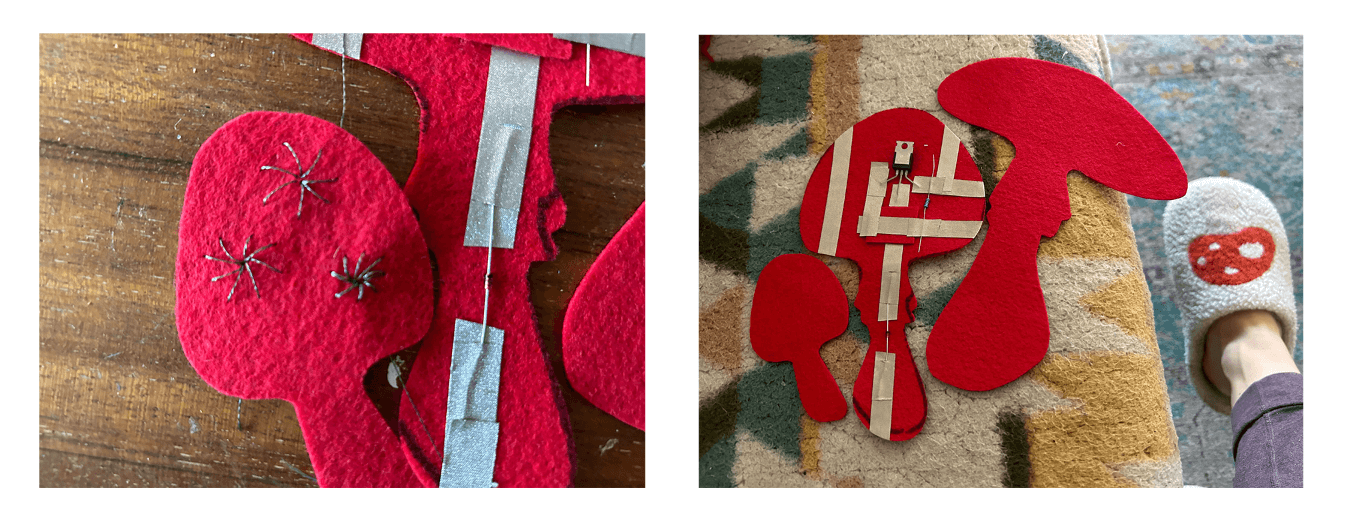
Figure 1. Mushroom season! My slippers inspired me to create a circuit with a theme of mushrooms. I decided to try to make a heating element circuit combined with thermochromic paint to build off my experience with it during the E-textiles week.
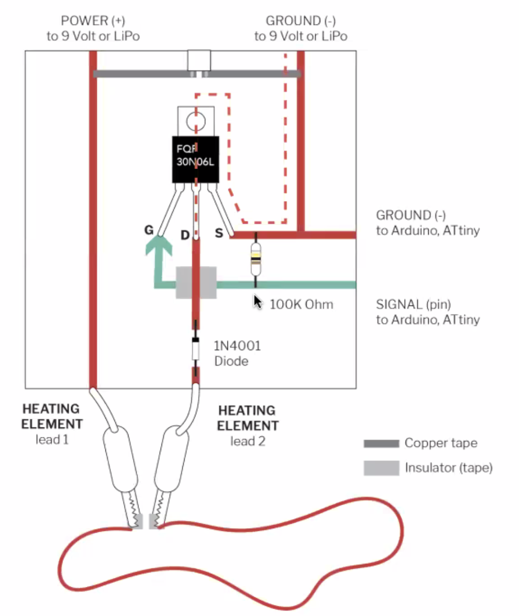
Figure 2. Heating element circuit diagram. Courtesy of Liza Stark. Found under lecture notes for 2023-24.
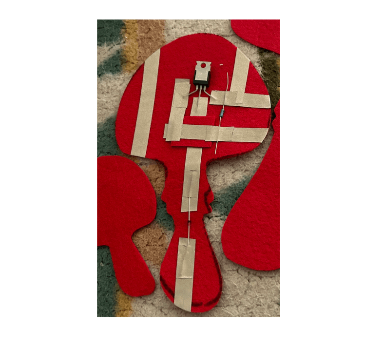
Figure 3. Heating element circuit close up. I used conductive fabric tape to adhere to the surface of the felt. Aesthetically, it's not great but the tape is very convenient for piecing together a prototype.
Video. Magic Mushrooms! Final product with thermochromic paint and heating element circuit.
Galvanic Skin Response Input and LED Actuator
I wanted to refine the galvanic skin response sensor I made in week 12. I realized after trying to play around with the original one I had made that it was only a capacitive touch sensor and only responded when I touched it and not in response to the electrical changes on my body which was the original idea. So after several hours of talking with Chat GPT I finally landed on a circuit and a code that would read the galvanice skin response. The galvanic skin response measures the electrical conductance of the skin. In this circuit the electrodes make direct contact with the skin and measure the electrical properties of the skin. I used conductive fabric as make shift electrodes as I did not have enough electrodes available at home.
I attached two electrodes to pins A1 and A2 on the Adafruit Gemma MO. I attached a grounding electrode to ground. The neopixels are set up in the same way as in week 12 for the Adafruit's Space Face LED Galaxy Makeup. Setting up the Gemma MO and libraries are all explained in week 12.
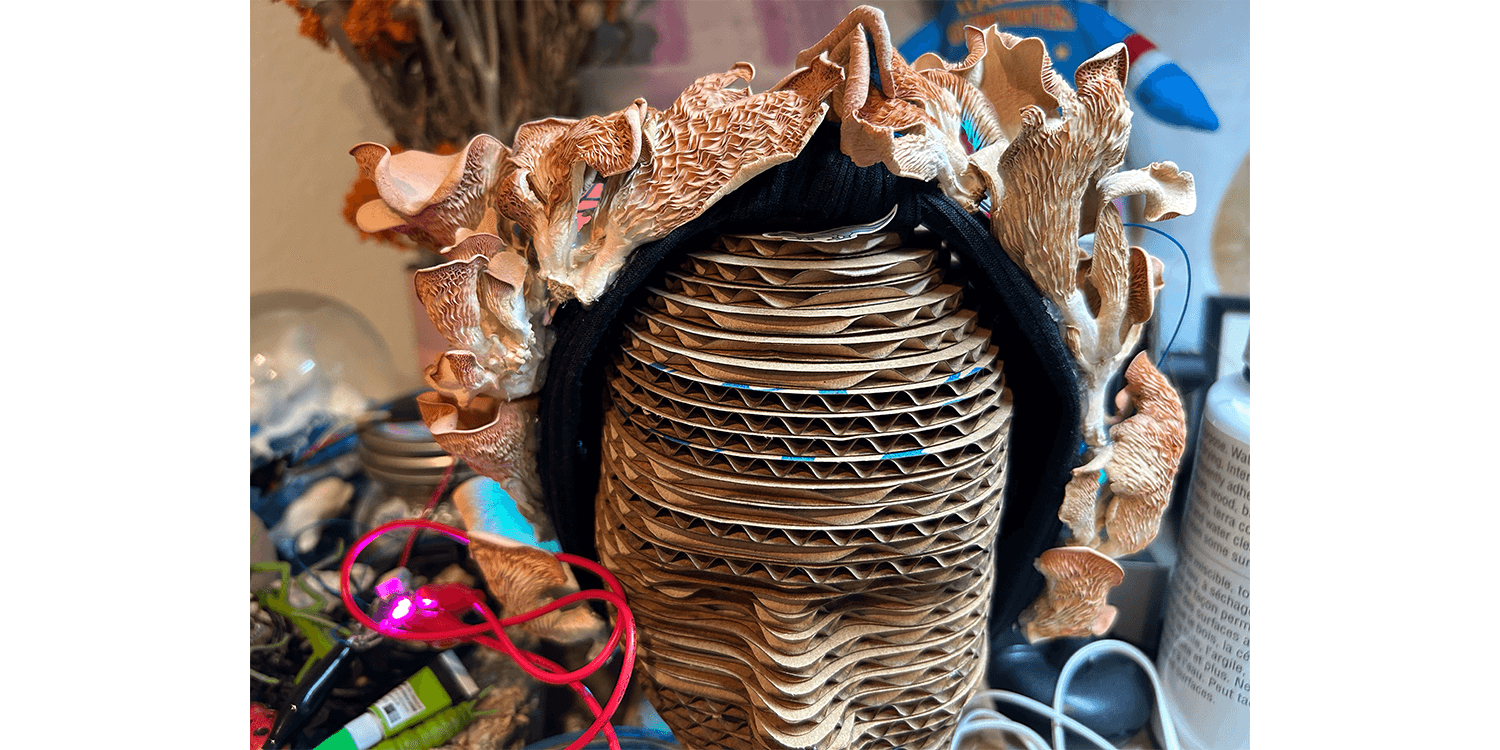 Figure 1. Mushroom Headband. I wanted to stick with the mushroom theme so I attached it to my mushroom headband.
Adafruit Gemma MO Notes: Bootloader Mode: If you press the reset button twice quickly, the Gemma M0 enters bootloader mode. In this mode, the Gemma is ready to receive new code to be uploaded to it. The red LED turning on could indicate that the board is in bootloader mode and ready to accept new code.
Discussion
I honestly wish I had more time to build all of the different circuits that were presented during this week. I am such a fan of electronics and e-textiles. I am looking forward to jumping back into these projects over summer vacation!
Methods and Materials
- Among Us e-textile kit, from FabLab Leon
- Conductive fabric tape
- Conductive thread
- FQP30N06L 60V LOGIC N-CHannel MOSFET
- Cotton fabric
- Thermochromic pigment
- 100k Ohm resistor
- 1N4001 Diode
- Arduino UNO
- Wires
Heating Element Actuator
from Liza Stark's "Wearables" lecture
const int heatingElementPin = 8; // Replace 8 with the actual pin number you are using

void setup() {
  pinMode(heatingElementPin, OUTPUT);
}

void loop() {
  // Start with smaller values and go up based on material
  digitalWrite(heatingElementPin, HIGH);
  delay(1000);

  // We always want to give the heating element and ink time to rest
  digitalWrite(heatingElementPin, LOW);
  delay(10000);
}
Galvanic Skin Response Input and LED Actuator
#include <Adafruit_NeoPixel.h>

#define NEOPIXEL_PIN A0
#define NUM_PIXELS 5
#define BRIGHTNESS 50

Adafruit_NeoPixel strip = Adafruit_NeoPixel(NUM_PIXELS, NEOPIXEL_PIN, NEO_GRB + NEO_KHZ800);

#define ELECTRODE_PIN_1 A1
#define ELECTRODE_PIN_2 A2

void setup() {
  // Initialize GSR pins for analog input
  pinMode(ELECTRODE_PIN_1, INPUT);
  pinMode(ELECTRODE_PIN_2, INPUT);

  // Initialize NeoPixels
  strip.begin();
  strip.setBrightness(BRIGHTNESS);

  // Initialize serial communication
  Serial.begin(9600);
}

void loop() {
  // Read analog voltages at electrodes
  int voltage1 = analogRead(ELECTRODE_PIN_1);
  int voltage2 = analogRead(ELECTRODE_PIN_2);

  // Calculate resistance using Ohm's Law
  float resistance = 10000 * (1023.0 - voltage1) / (voltage1 - voltage2);

  // Output resistance value to serial monitor
  Serial.print("Resistance: ");
  Serial.println(resistance);

  // Update NeoPixel color smoothly like a rainbow based on resistance
  updateNeoPixels(resistance);

  // Delay between readings
  delay(1000);
}

void updateNeoPixels(float resistance) {
  // Calculate hue value for smooth rainbow gradient based on resistance
  uint16_t hue = map(resistance, 0, 1023, 0, 255);

  // Fill NeoPixels with smooth rainbow gradient
  for (int i = 0; i < NUM_PIXELS; i++) {
    strip.setPixelColor(i, strip.ColorHSV(hue));
  }

  strip.show(); // Update LED colors
}