05_E-TEXTILES
This week we explored the relations between electricity, materials, and fabrics, by designing a soft circuit, an e-textile.
Overview
E-textiles are fabrics in which electronic components (sensors, chips, batteries, lights, microcontrollers, etc.) are embedded. They represent the main parts of wearable technology and smart clothing. In e-textiles, the choice of fabrics used in the design, often plays with the manipulation of the resistance of the materials, resulting in different information outcomes. That is achieved by building different structures and layouts of materials, and fabrics. Designing a circuit embedded in the textile in a way that a person can touch, feel, and wear it, makes e-textiles great translators for different types of information. Because of that, they are also widely used for medical purposes, such as health monitoring for vital organs, heart rate, respiratory rate, temperature, etc.
Inspiration and Reference
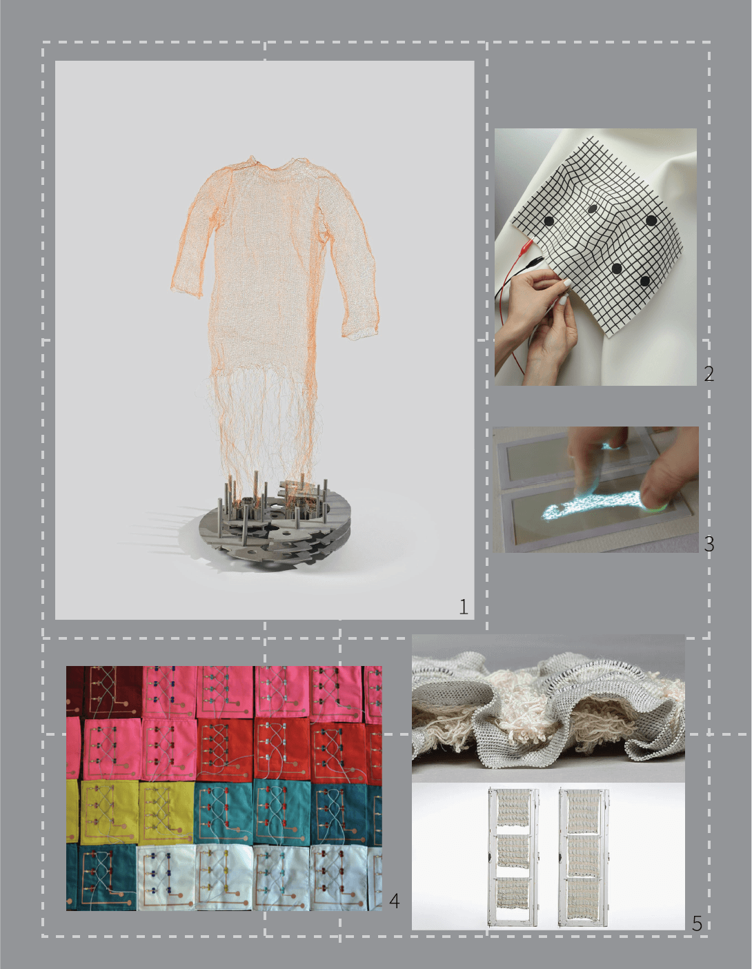
1 – Julijonas Urbonas, When accelerators turn into sweaters
Basics of electricity and materials for designing an e-textile
Liza Stark carried out the global lecture on electronics. She introduced us to the basics of how electricity works, how to connect all the components into a system properly, and which main properties to consider when designing with conductive materials, such as resistance, flexibility, stretching the fabric, bending it, and how it feels to the skin. Threads and yarns can also be a nice idea to work with since they can be very conductive (such as silver yarn) and can have a nice aesthetic touch to the design. To design a circuit, you can also use conductive ink, electric paint, and different types of conductive tapes.
Some basic symbols for electricity:

Basic circuit sketch:
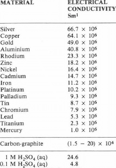
The most conductive materials:
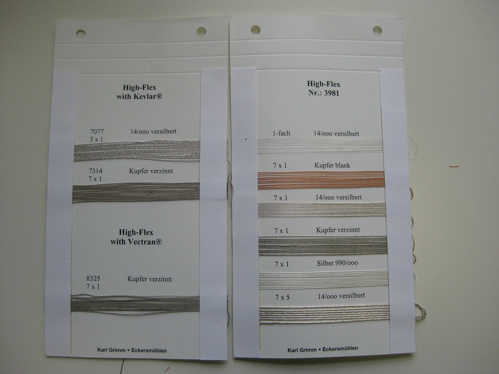
Conductive textiles I found on HOW TO GET WHAT YOU WANT. More on the topic of conductive materials and yarns can be found here. A nice description of these materials is also available onSaskia Helinska's page:

Conductive yarns and other very helpful information about them, can be found here. The primary uses of conductive yarns are stretch, pressure, and bend sensors. Resistance decreases across distance and changes under the pressure.
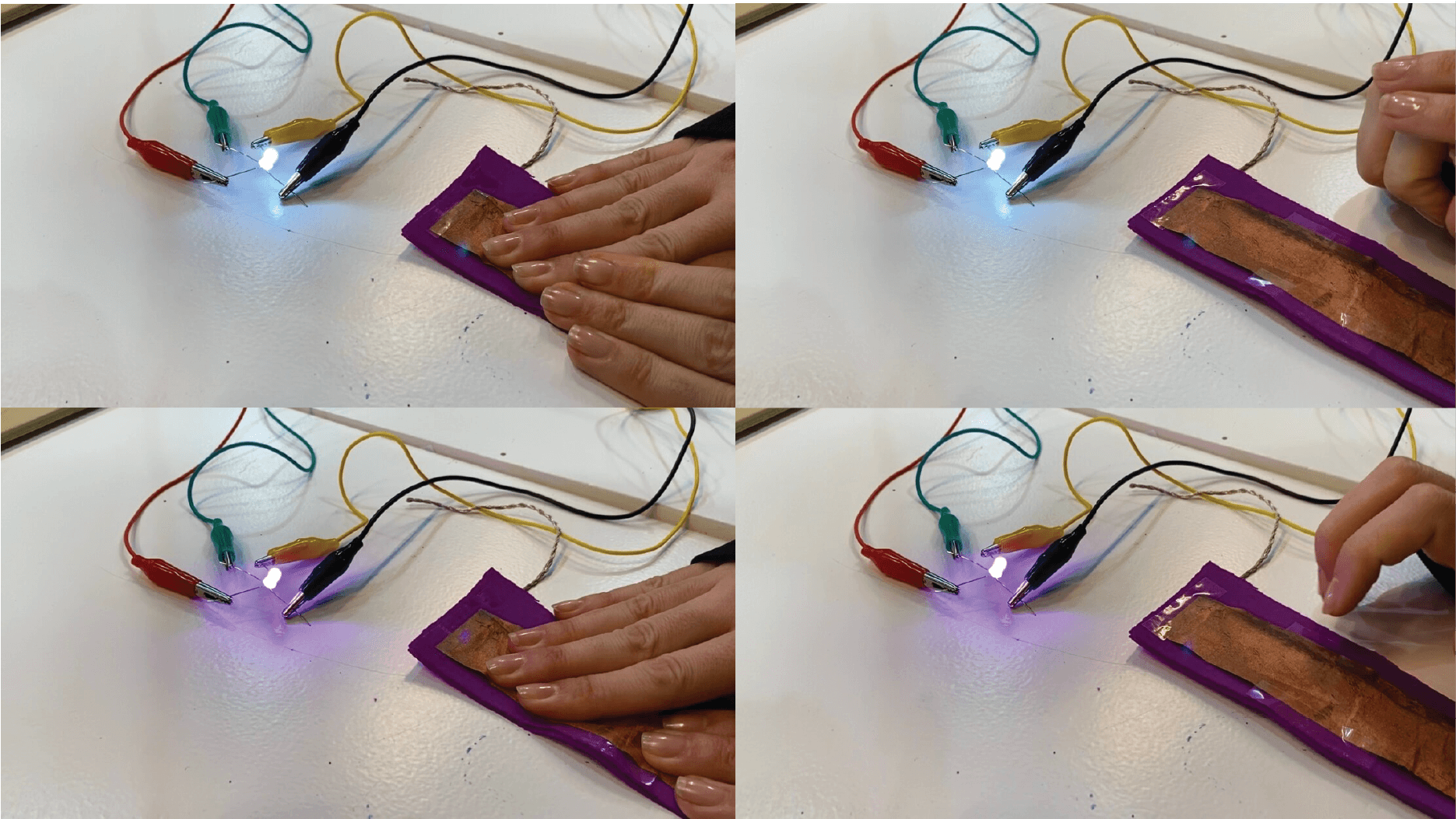
Conductivity and resistance materials
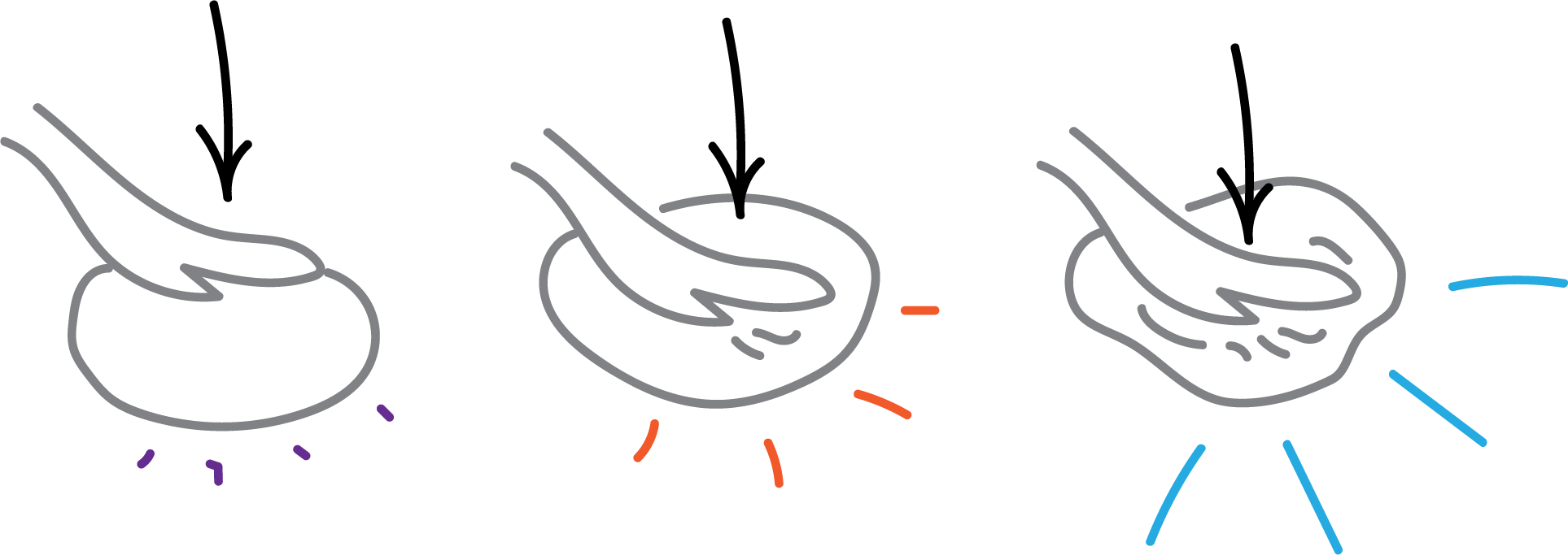
The primary use of resistance materials is applying pressure or bending them, making them a perfect material for creating a sensor. Physical manipulation of the material, which affects the circuit flow, results in the energy outcome, for example, increasing or dimming the LED light.
When resistance material is pressed, resistance decreases, allowing more electricity to flow through the circuit. Resistance is measured in OHMS.
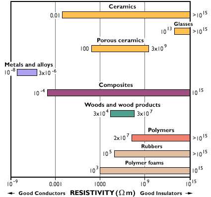
Resistivity chart showing different types of materials based on their conductivity or insulating properties.
- Velostat (most common used) – carbon-impregnated black polyethylene film. Conductivity with this material is not affected by humidity or ageing

- Eeontex
- Polysense

An example made with velostat foil and more on that topic, can be found in this paper
Connections between soft and hard materials:
- Permanent
- Detachable
- Pressure and bending
Tools and helpful links this week:
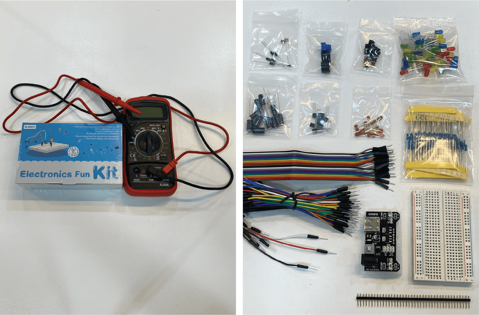
- Multimeter
- Alligator clips
- Electronics fun kit: breadboard, LED lights, resistors, switch buttons, ..
- Resistivity chart, calculator
- Resistor calculator with colors
- About conductivity
- HOW TO GET WHAT YOU WANT
- How does LED RGB light works
- Arduino
- Arduino maping
- Arduino and SeedStudio
- HTML color picker
Class experiments
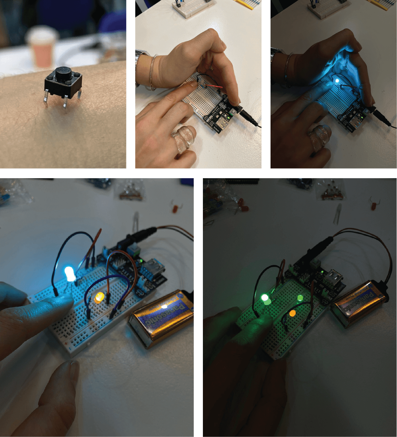
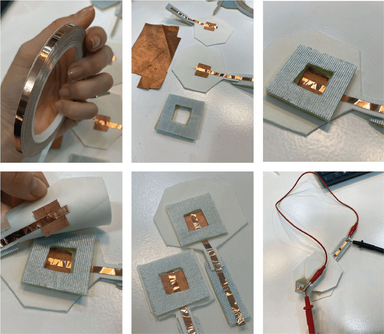
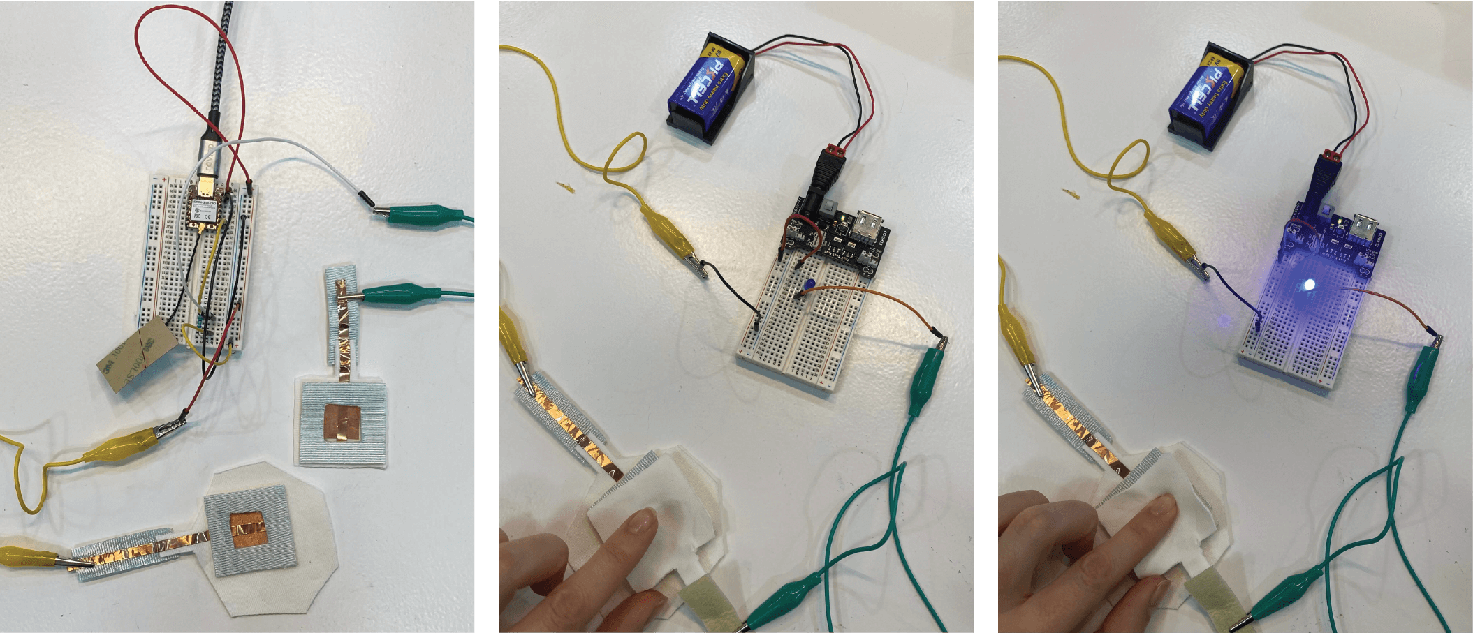
After the global lecture, we had two local ones, carried out by Gerard on the first day and Citlali Hernández Sánchezon the second one. Gerard showed us the first steps into getting to know the electronics design kit, which was our playground for the assignment. It was all about exploring how to properly connect all components and make a simple (or not 😊 ) circuit, and later on, incorporate it into the digital switch design.
Electronics fun kit experiments and some basic connections:


Making a connection and a button switch
A switch = is a break in the circuit.
Push buttons, toggle switch, zip, slide, tilt, physical pressure, pressing conductive materials into contact, pressing resistance materials into contact…
Dimming switch:
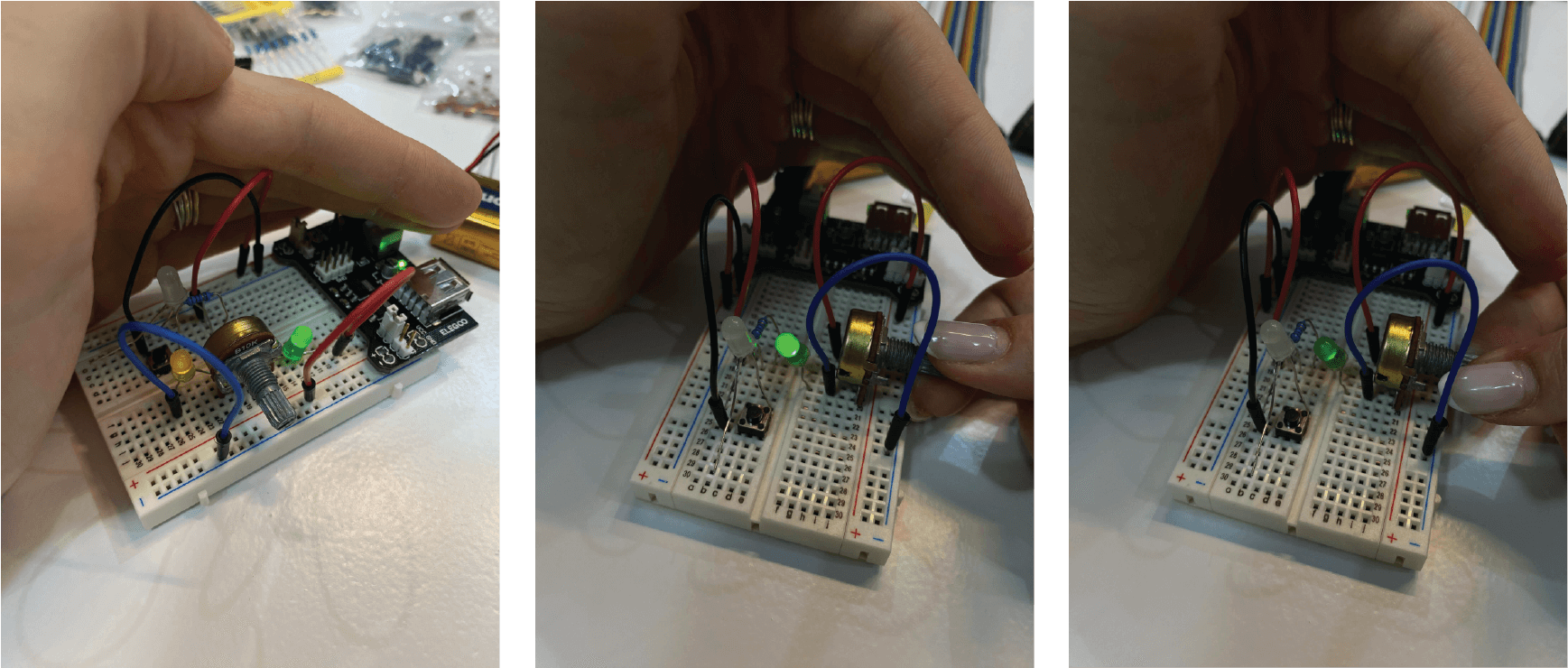
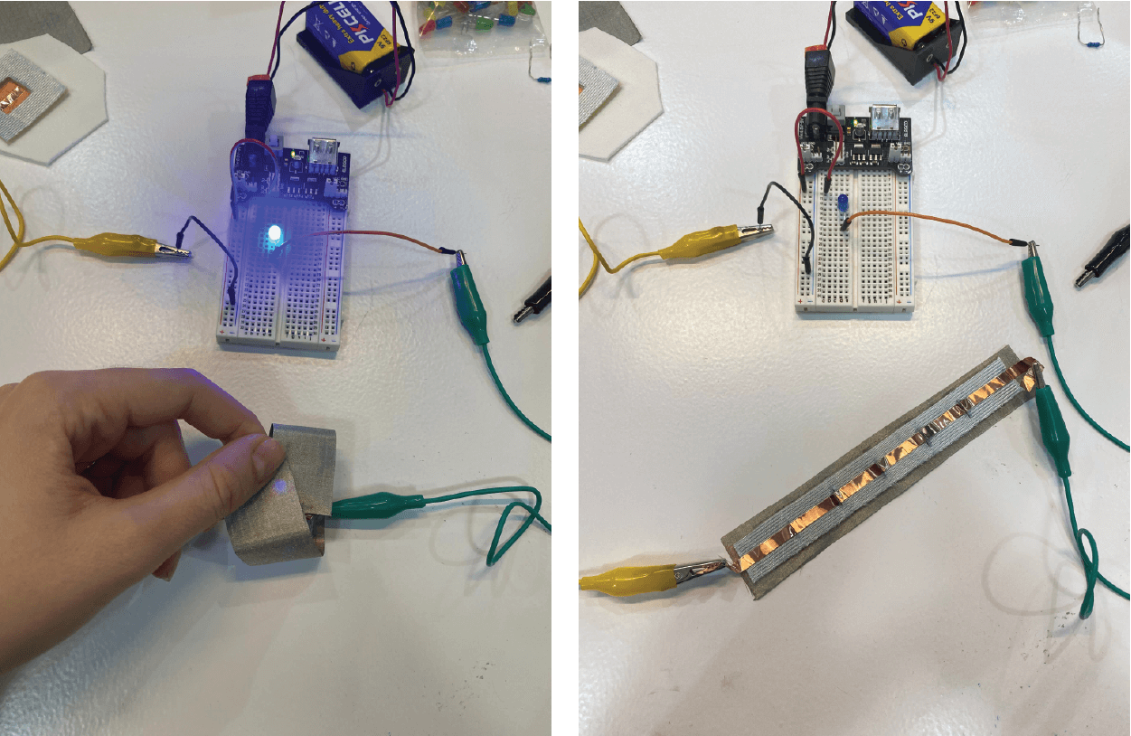
Making a digital switch and a sensor prototype
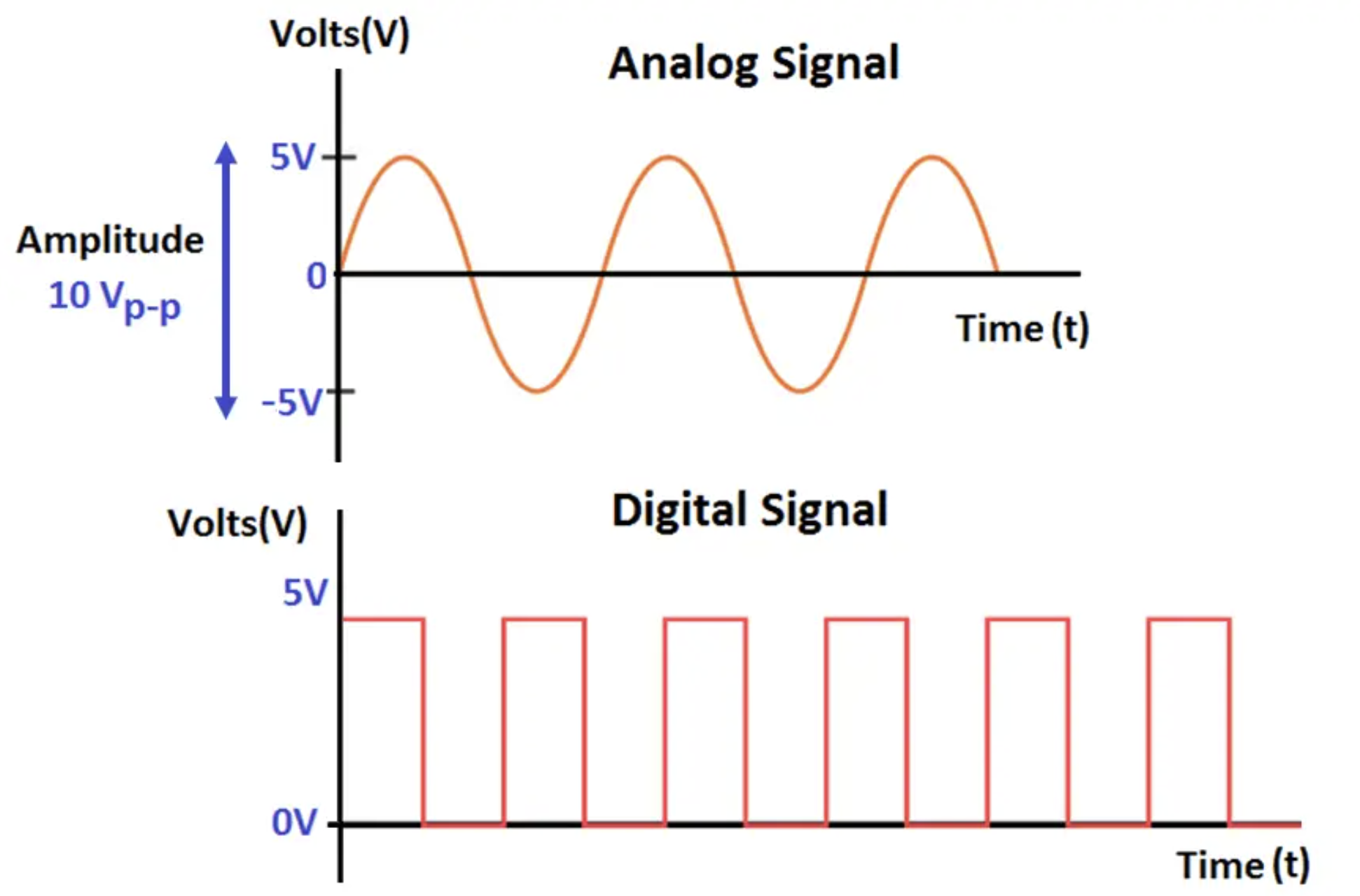
A digital switch is a binary, ON/ OFF switch, read in bytes ( 8 x 8 (1,0), example of a 1 byte = 10010101). The monitoring for digital sensors is a limited set, shown in a square wave, showing only two kinds of signals, magnitudes (on or off).

Code used for readings:
int digital_sensor_pin = D7;     //change the pin, where the sensor is connected
int digital_sensor_value = 0;   //variable in which we save the sensor voltage

void setup() {
  // put your setup code here, to run once:

  //pinMode(digital_sensor_pin, INPUT);
  pinMode(digital_sensor_pin, INPUT); //define the pin as INPUT PULLUP
  Serial.begin(9600); //open communication

}

void loop() {
  // put your main code here, to run repeatedly:
  // digitalRead(pin);
  digital_sensor_value = digitalRead(digital_sensor_pin); // read the sensor

  Serial.print("the status of the sensor is: ");
  Serial.println(digital_sensor_value); //print the value
  delay(100);

}
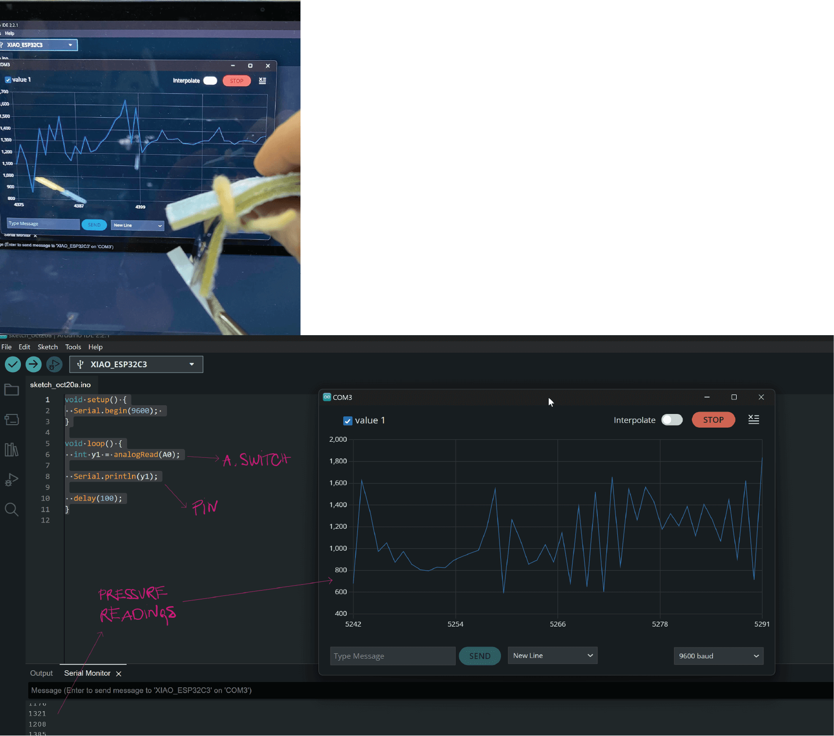
Getting to know Arduino and working with XIAO-ESP31-C3


Making an analogue switch and a sensor prototype
The analogue sensor values range from 0 – 1023, creating analogue signals from the quantity (pressure on the materials, resistance) that is sensed. The most common analogue sensors are light sensors, sound sensors, temperature, and pressure sensors. This system uses continuous signals with varying magnitudes, resulting in a wavy reading graph.

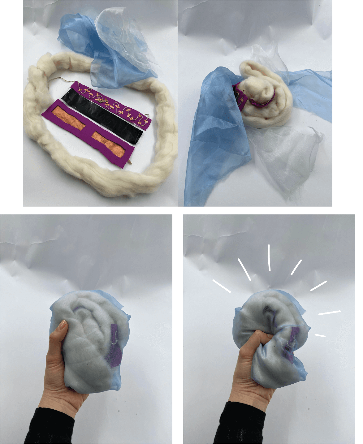
_Ideation

Code used for readings:
const int redPin = D4;
const int greenPin = D5;
const int bluePin = D6;
const int sensorPin = A0;

void setup() {
  pinMode(sensorPin, INPUT);
  pinMode(redPin, OUTPUT);
  pinMode(greenPin, OUTPUT);
  pinMode(bluePin, OUTPUT);
  Serial.begin(9600);  // Initialize serial communication for debugging
}

void loop() {
  int y1 = analogRead(A0);
  Serial.println(y1);
  if (y1 < 250) {
    analogWrite(redPin, 153);
    analogWrite(greenPin, 0);
    analogWrite(bluePin, 204);
  } else if (y1 > 250) {
    analogWrite(redPin, 255);
    analogWrite(greenPin, 102);
    analogWrite(bluePin, 0);
  } else if (y1 > 1000) {
    analogWrite(redPin, 0);
    analogWrite(greenPin, 255);
    analogWrite(bluePin, 255);
  }
}