07_COMPUTATIONAL COUTURE
Overview
This week we will be working with 3D printer, algorithms and Rhino's Grasshopper, all completely new to me :)
We started with an engaging global lecture by Julia Körner, where she introduced her work and the principles of 3D printing. The possibilities within this week's topic are truly limitless.
Computational couture is the term used to describe the intersection of fashion design and computational technologies. It involves integrating digital tools, such as parametric design principles, electronic components, and programmable materials, into the creation of garments, accessories, and wearables. These principles are also widely used in architecture. It is an interesting field to explore as it plays a crucial role in material ecology and sustainable advanced technology processes through mimicing nature's design principles and practices - biomimicry for resource efficiency.
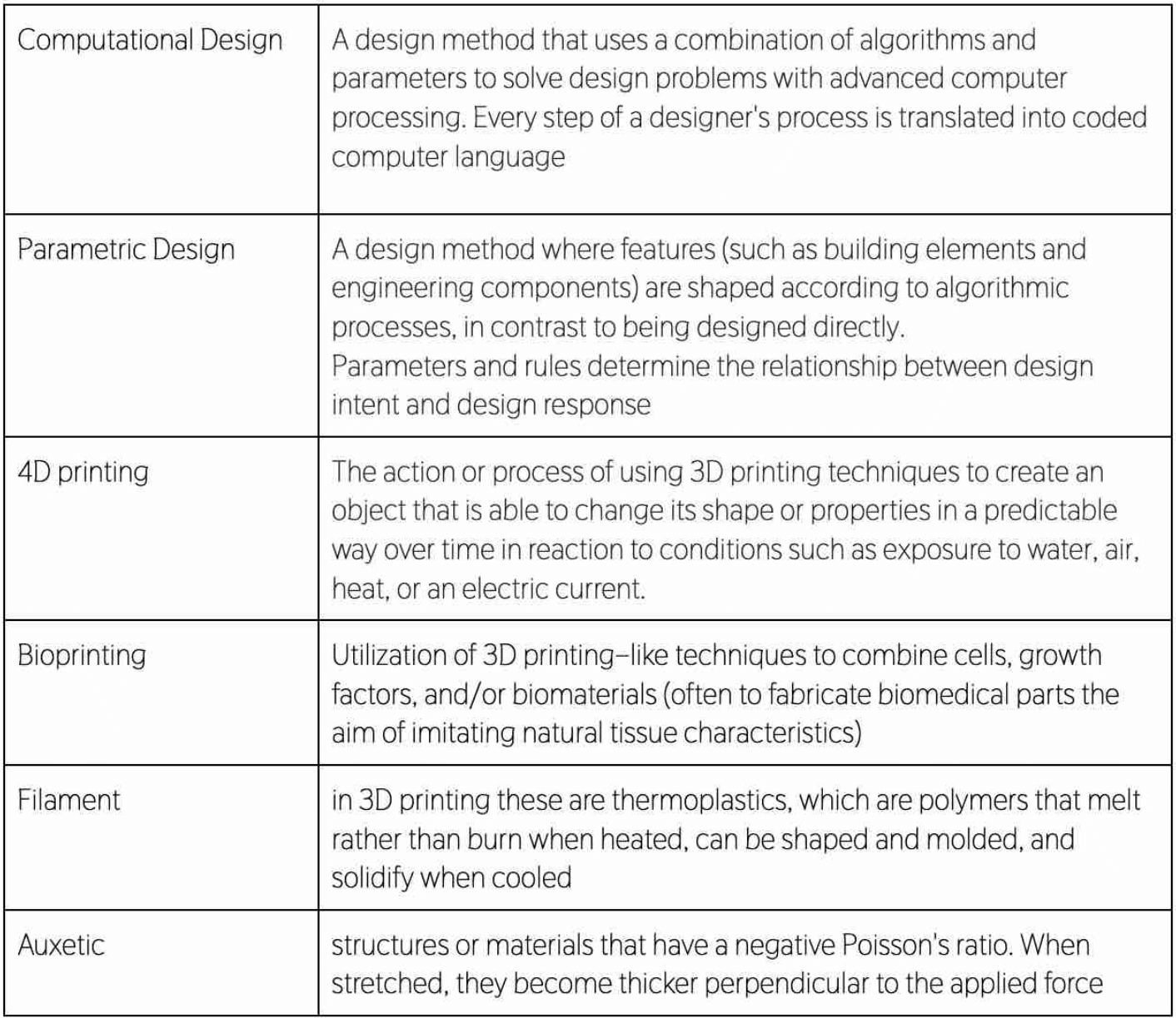
Some important terms found on Anna's page
Inspiration & References
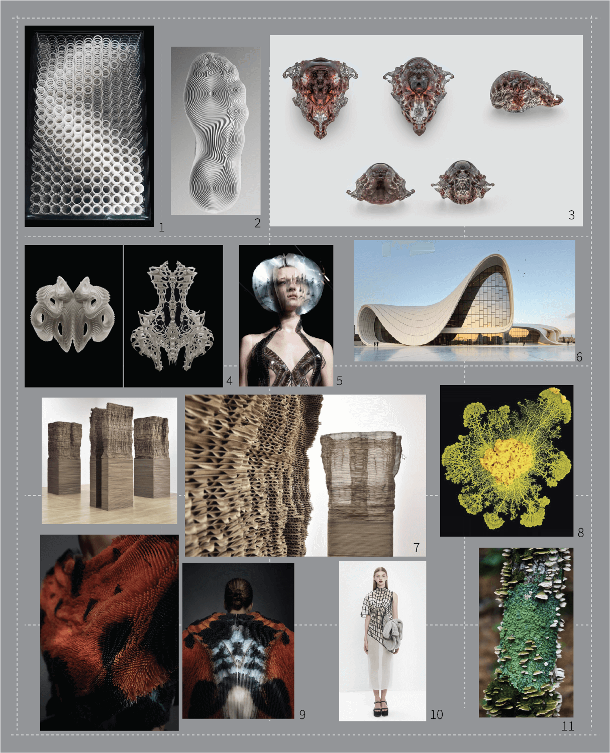
1 – Helga Philipp – Kinetische Objekt, 1970
2 – Nike sole pattern
3 - Neri Oxman – VESPERS II, 3D printed death masks
5 - Iris Van Herpen translates motion of bird flight into pleated garments
6 – Zaha Hadid - Heydar Aliyev Centre, Baku, Azerbaijan, 2007 – 2012
7 - Tobias Putrih – Macula Series
8 – Blob, Fuligo septica
9 - Julia Körner – SETAE, 3D print on fabric inspired by microscopic butterfly wing patterns
11 – Tree lichen
12 - Biomimetics for resource efficiency
Fabricademy students references:
Digital fabrication, additive manufacturing and 3D priniting technologies
Additive Manufacturing (AM), which is commonly referred to as 3D printing, is a manufacturing process that creates 3D objects by adding or layering material one layer at a time. As opposed to traditional subtractive manufacturing methods, where material is removed from a larger block or sheet to create the final shape, additive manufacturing is known for its versatility, efficiency, and ability to create complex and customized geometries, for example with parametric design principles.
Key aspects:
-
Layer-by-layer construction: The process of layering can be repeated multiple times, depositing and solidifying materials within the process. Depending on the requirements of the design, the process and final outcome, different materials can be used fort his technique.
-
Digital design: The process begins with a digital 3D model created using computer-aided design (CAD) software, in our case a Grasshopper for Rhino. The digital model then is sliced into thin layers (fabrication process), with information on the amount of layers of the design and the time of fabrication. In our case we used a program UltiMaker Cura.
-
Usage of different materials: Additive manufacturing can use a wide range of materials, including plastics, metals, ceramics, and even biological materials – 3D BioPrinting
-
Allowing to create complex geometries: With the use of parametric design principles, 3D printing technologies allow you to produce designs that would be impossible to achieve with traditional manufacturing
-
Reduced material waste: oppose to subctractive manufacturing processes, additive one is considered more material-efficient, adding material only where needed. The thing to consider when proposing this idea is, the amount of prototypes on a bigger scale that are enabled with this technique, many times resulting in a lot of waste. Also considering energy, time..
-
Production of rapid prototypes
-
Customization, personalization and on-demand production
3D priniting technology can be used endlessly for various reasons. Some of them are shown in schematic below. More on that topic can be found here.

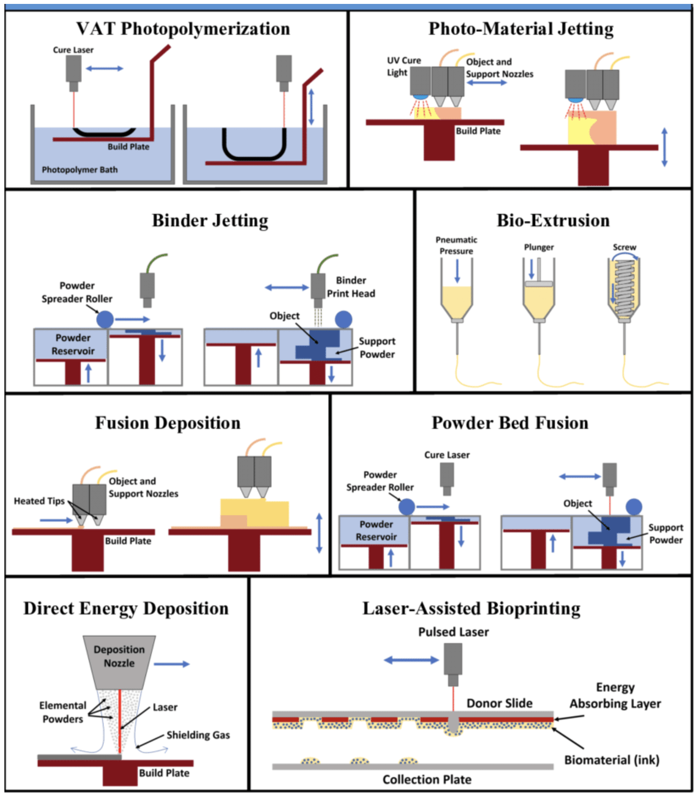
Types of 3D printing technology
Julia Koerner carried out a beautiful and in-depth presentation of different AM technology principles and outcomes. Some of the main ones are explained below:
• Fused Deposition Modeling (FDM): Thermoplastic filaments are heated and extruded layer by layer to create the object.

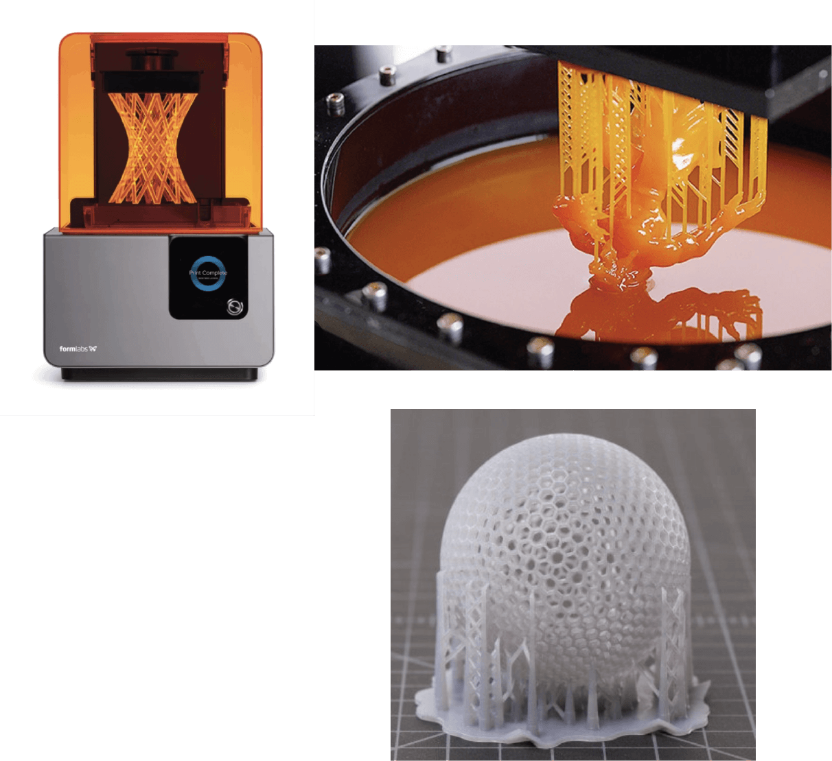
• Stereolithography (SLA): Liquid photopolymer resin is selectively cured by UV light to build the object.
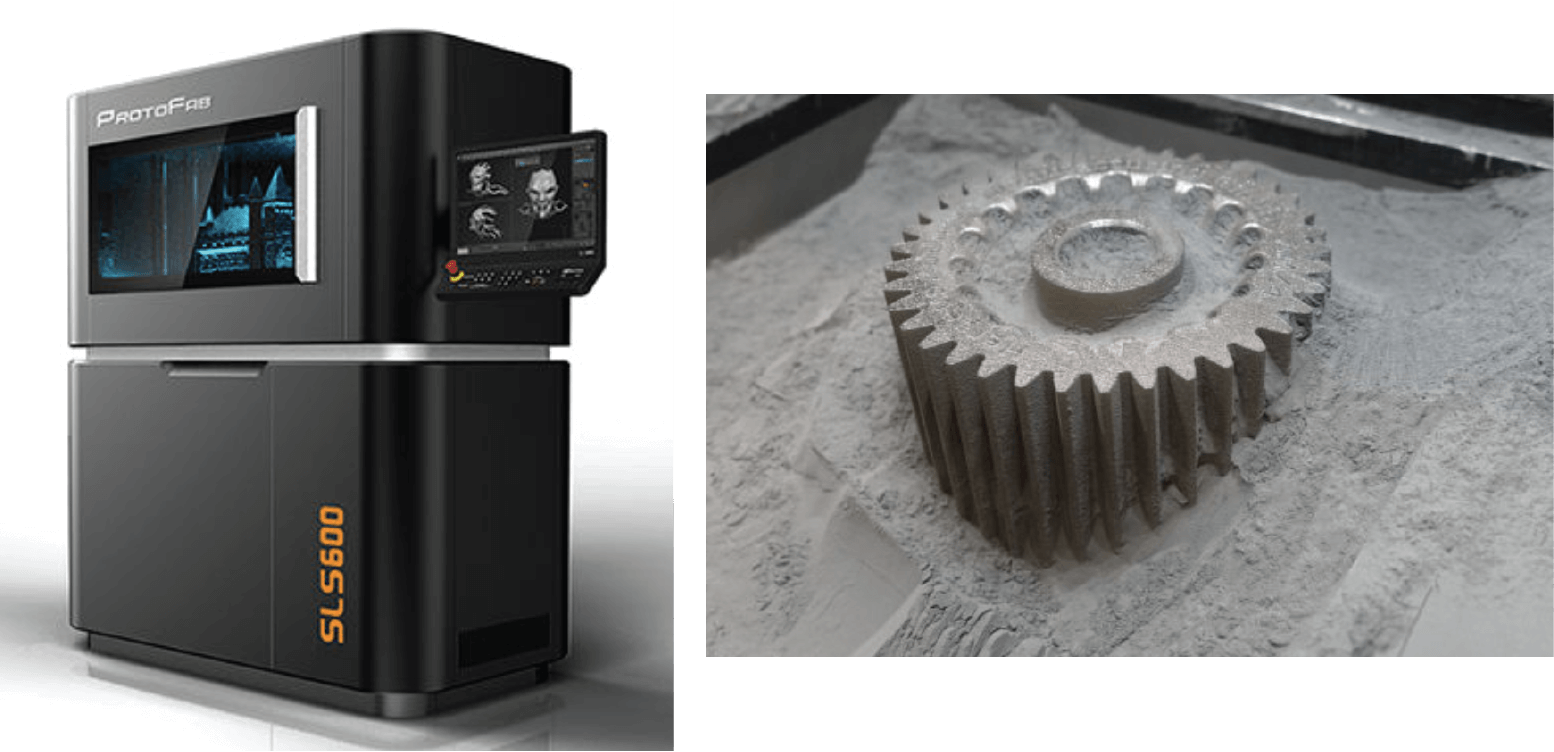
• Selective Laser Sintering (SLS): Powdered material, such as plastic or metal, is selectively fused by a laser to form the object.
• Material Jetting: Droplets of liquid material are selectively deposited and solidified layer by layer.

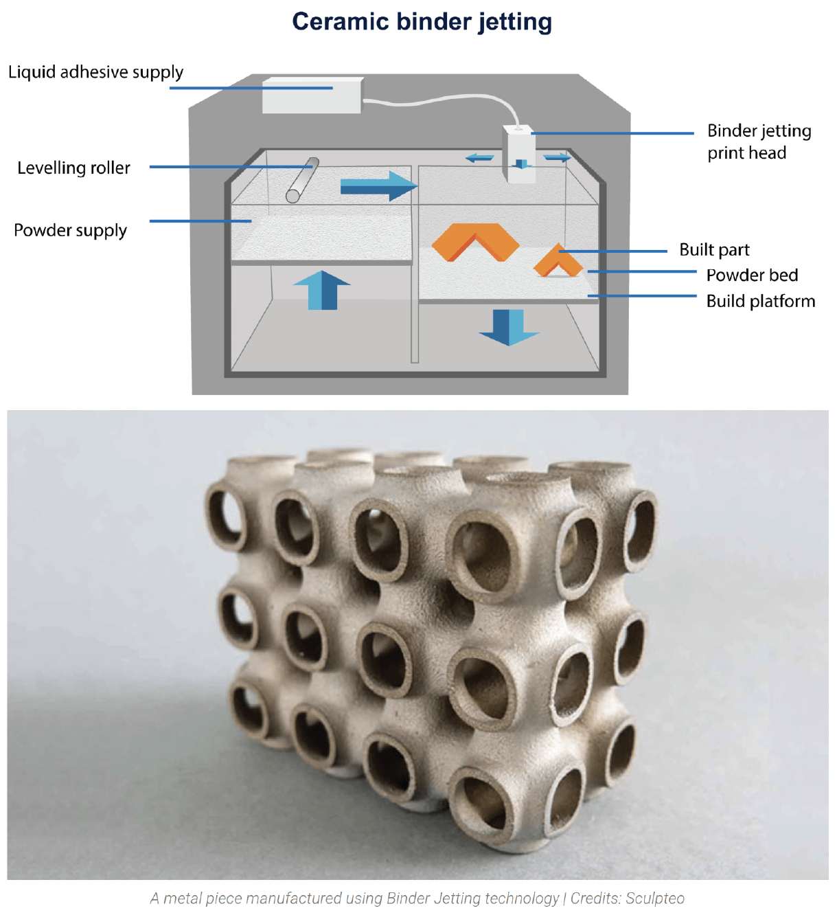
• Binder Jetting: Liquid binder is selectively deposited onto a powder bed to create the object. More on aqui.
• Direct Metal Laser Sintering (DMLS): Metal powder is fused by a laser to build metal objects.

Materials for 3D printing

• TPU filament - Thermoplastic Polyurethane, is a flexible filament known for its elasticity, durability, and resistance to abrasion and oils
• PLA filament - Polylactic Acid, is a biodegradable and bioactive thermoplastic polymer derived from renewable resources such as corn starch or sugarcane
• PETG - Polyethylene Terephthalate Glycol, is a type of 3D printing filament that combines the advantages of both PLA and ABS, known for its durability, high strength
• ABS - Acrylonitrile Butadiene Styrene
• SLA
• Biomaterials, biocomposites
• Clay
• Ceramics
• Metals, etc..
More on properties of 3D printing materials can be found here
Rhino and language of Grasshopper
This week we dived into Grasshopper. For me this was the first time using it. This tutorial helped me a lot whit learning the basics and navigating through the Grasshopper language.
Check Emma's Picanyol page, she has a really nice presentation on the basics of Grasshopper language.
Grasshopper is a visual programming language and graphical algorithm editor for Rhinoceros, a 3D computer-aided design (CAD) software.
Grasshopper tutorial notes on how it works..
NOTES:
-
Grasshopper: algorithmic plug-in for rhino, giving us parametric control over a series of relations. A method of visual coding. Visual programming allows us to algorithmically generate geometry by composing diagrams that link DATA to FUNCTIONS
-
INPUTS, OUTPUTS: giving the control of properties of our object, little ears on the ends
-
Every change happens in the Grasshopper view, not in Rhino
PARAMETRIC CHANGES:
-
Number slider: attach to ''battery'' (object)
-
Panel: a useful tool for using your inputs
-
CONTAINERS: point container, surface, mesh, A BREP – POLYSURFACE
-
Parametric relationship = relationship between two objects we deifne; READING left to right
-
BAKING GEOMETRY: duplicating but only in Rhino; right-click on the component and BAKE OPTION; no parametric relations to the one in Grasshopper
-
SCALE COMPONENT: connect to the object – you can create a new object by baking one and then change relations to the new one
-
PREVIEW: right corner; to selected object only, the wireframe preview, the draw shaded preview
-
Disabling components in Grasshopper: DISABLE – NOT COMPUTATIONAL – you no longer have the connection to the input; affecting the parametric relations: attention to what property you're doing that
-
GRASSHOPPER PROFILER (shows you the speed of the components and how they computing; WHAT'S CAUSING THE SLOWNESS): go to display --> canvas widgets --> profiler --> populate 2D component (right click on screen) --> creates random population of 2D points: plug that into MESH SPHERE COMPONENT: if it shows red IT'S SLOW (7ms), better to unplug that component
Let's design something:
-
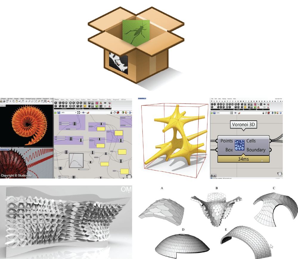
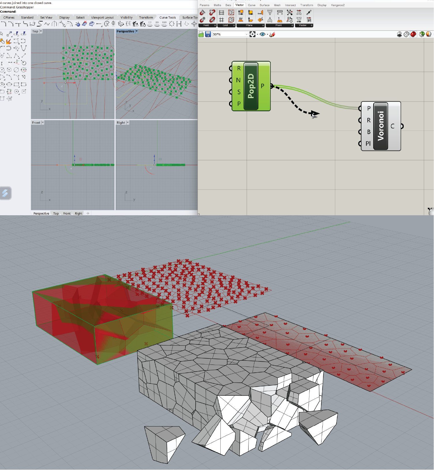
VORONOI PATTERN = a way of defining regions based on a collection of points and they usually produce patterns seen in nature: go -- mesh tab -- voronoi component -- click and on canvas
-
CREATING POINTS: go to --> vector tab --> grid drop menu --> populate 2D -> creates collection of points within a boudary (rectangular in the learning video) within a grosshopper
-
Rectangle it's a region and a boundary --> connect the populate 2D to points Voronoi; region and boundary: + create a new rectangle right click on the rectangle, duplicate
Voronoi From 2D to 3D swatch:
-
Create a new Voronoi relation
-
Surface input --> create a plane in Rhino
-
Populate geometry component
Ideation
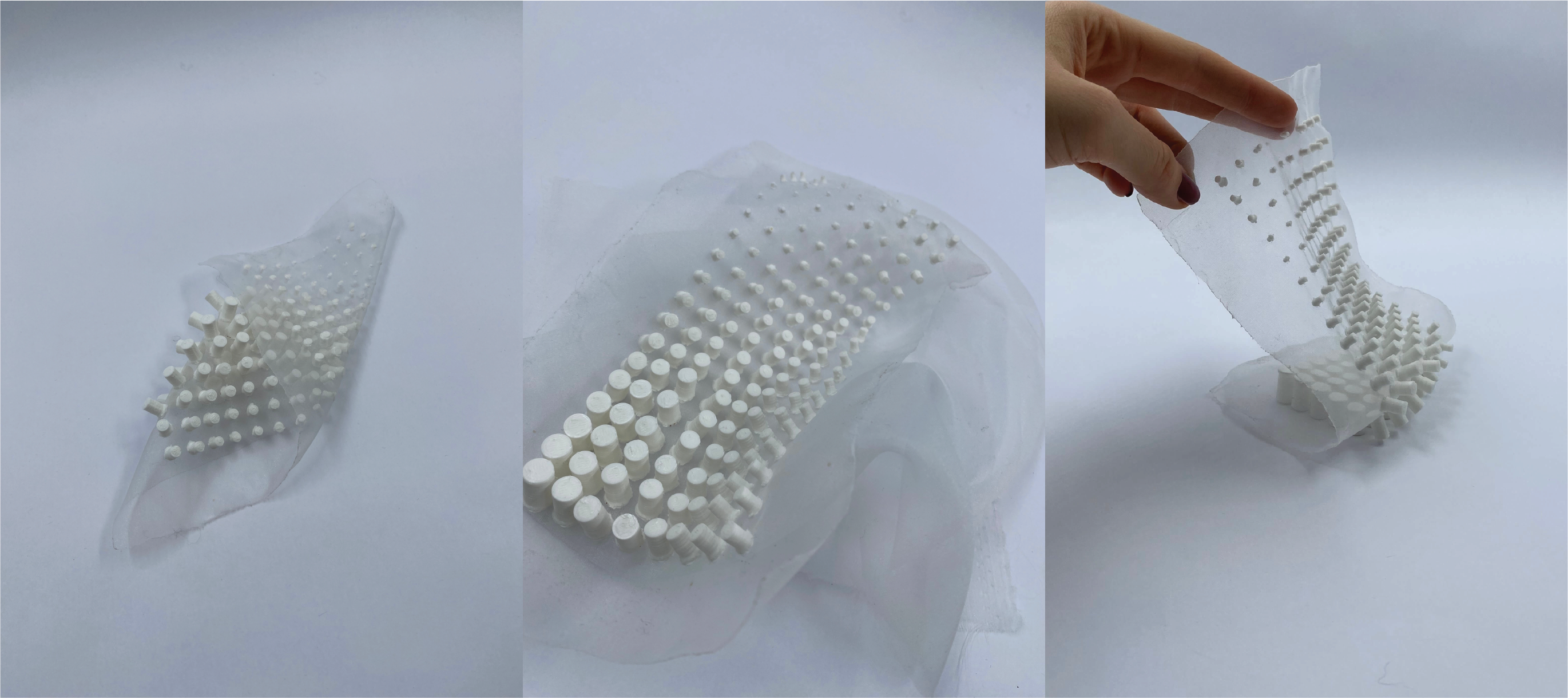
For the assignment, I continued with the work on the design I made by watching the tutorial. I got inspired by Julia Koerner SETAE project in collaboration with Stratasys manufacturer.
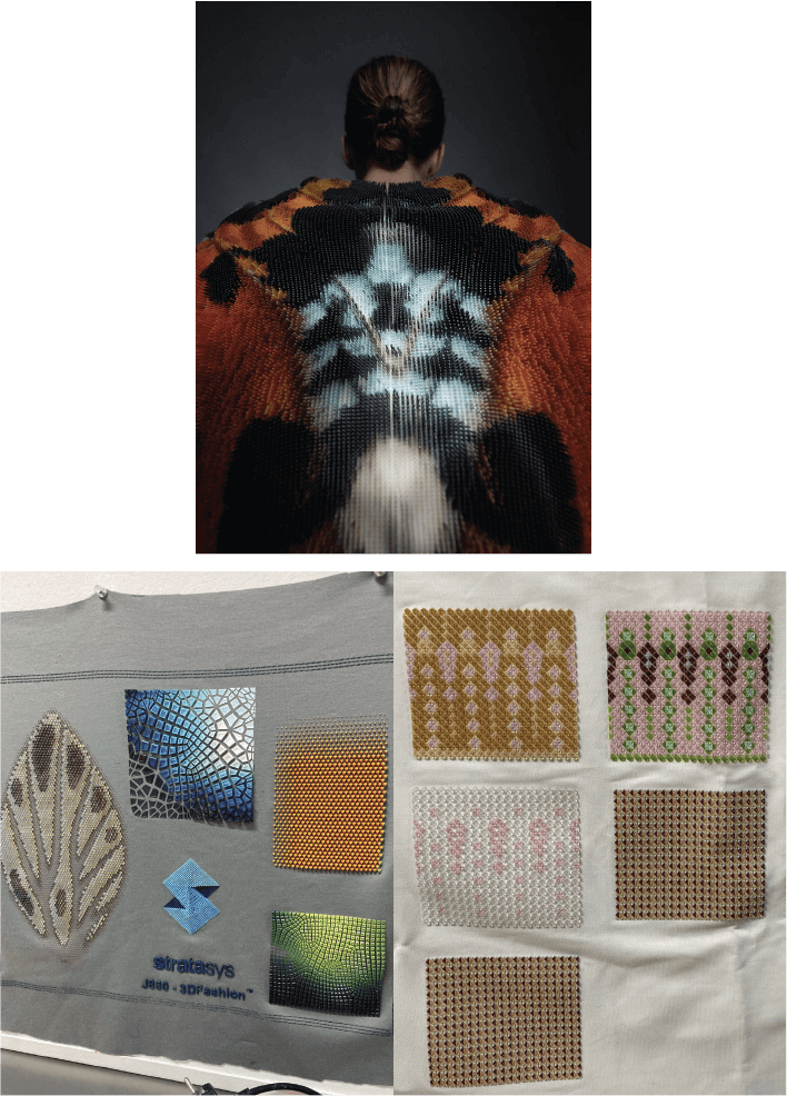
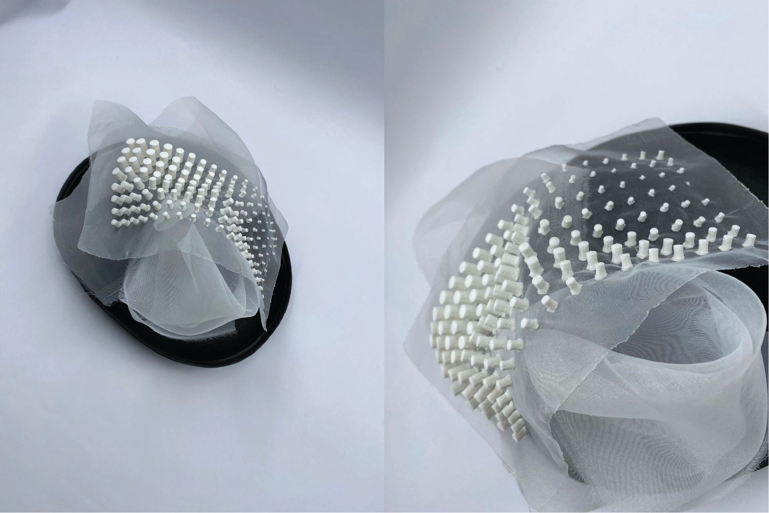
I wanted to experiment with printing on fabric since it was my first time seeing this technique. I printed on organza with PLA filament.
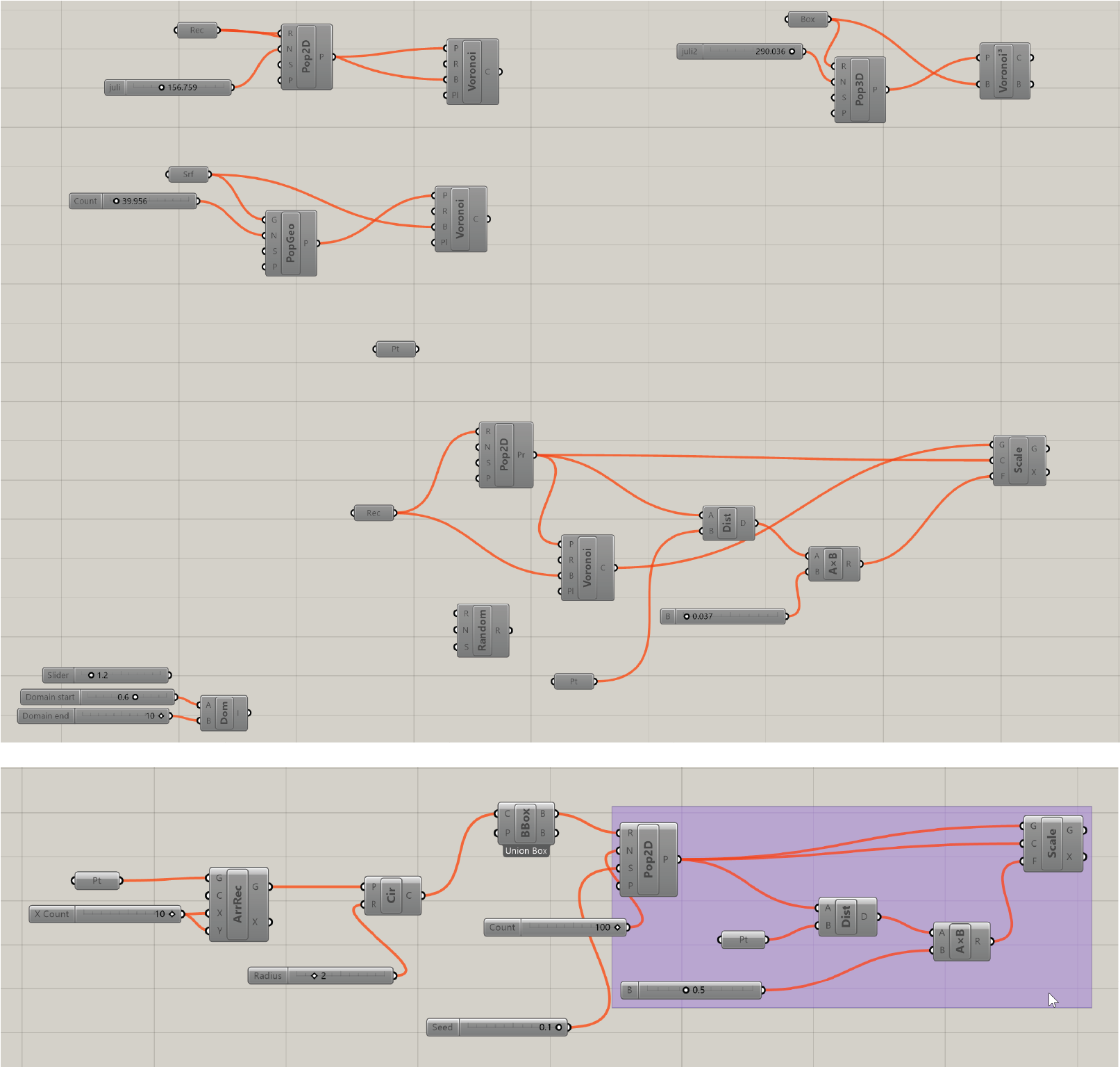
Preparing the design in Grasshopper
Step-by-step 3D printing on fabric
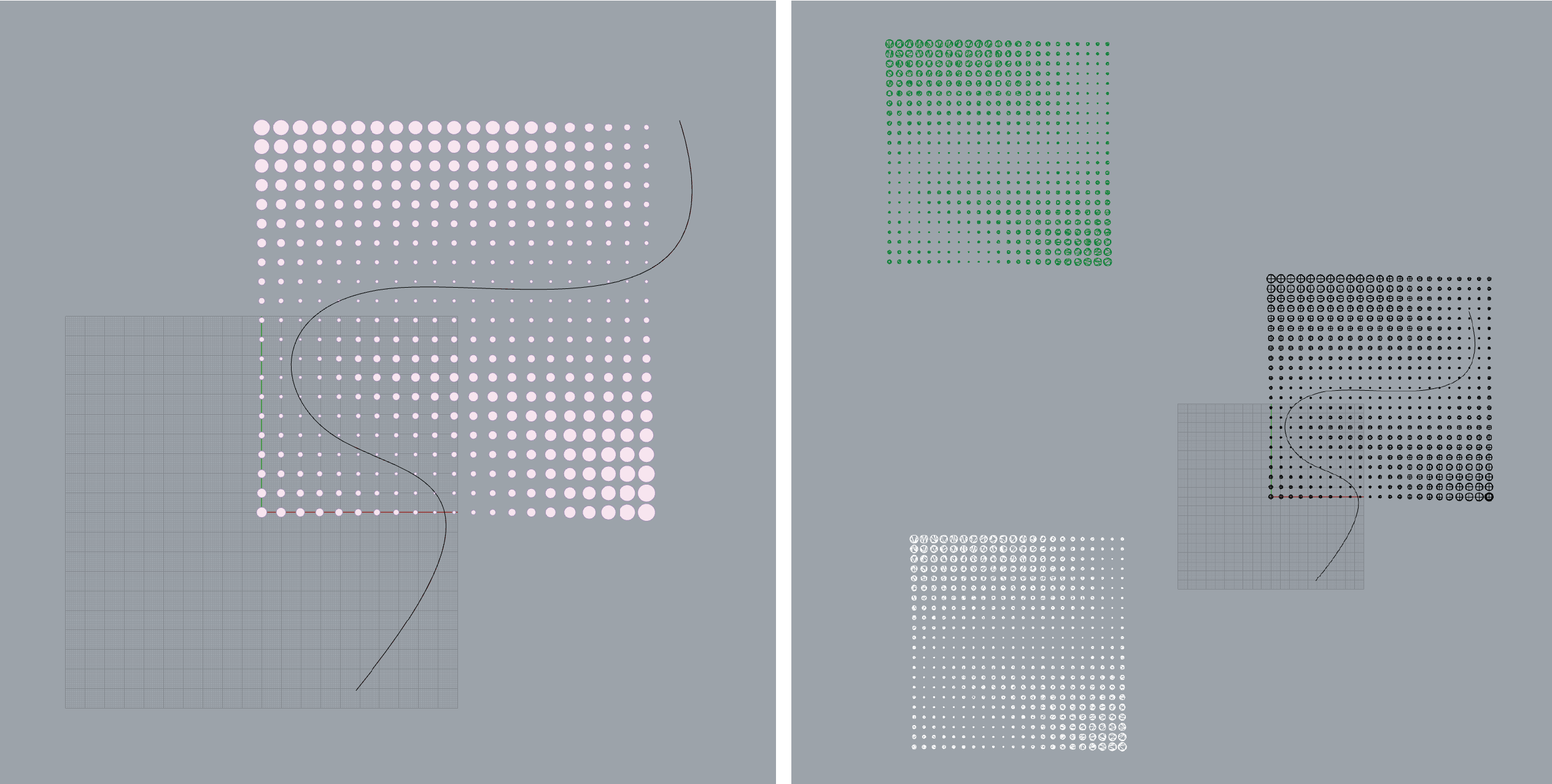
Step 1 – Creating the CAD model with Grasshopper, following the YouTube turtorial. I checked how to make a Voronoi pattern and played around with parametrics.
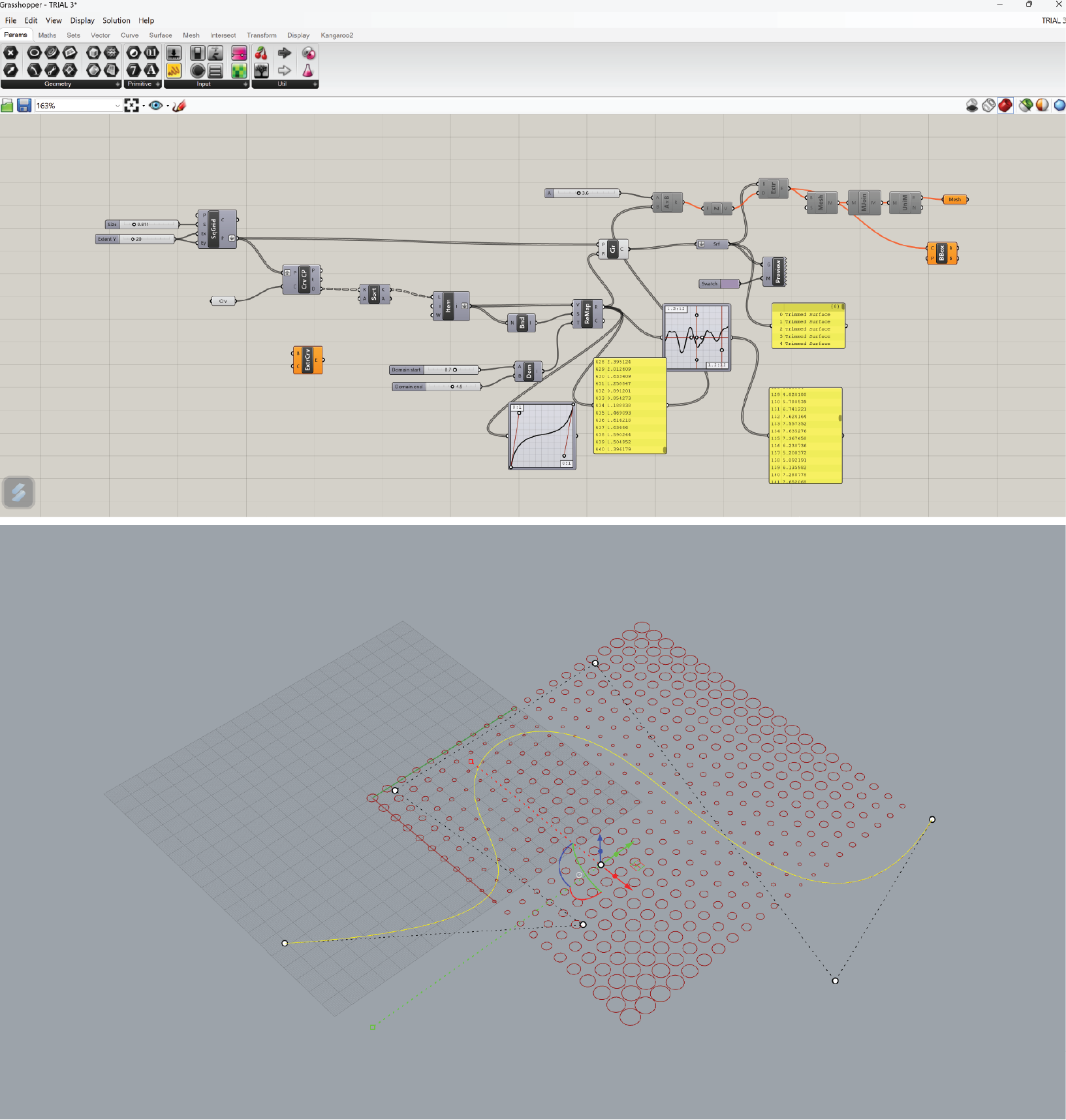
Step 2 – Once done, I took a part of the pattern square. After that I made a MESH and BAKED it. NOTE: The printing time of the whole square would take too long (12h+). I had to resize the model and choose only a part of it to print (2,5h).


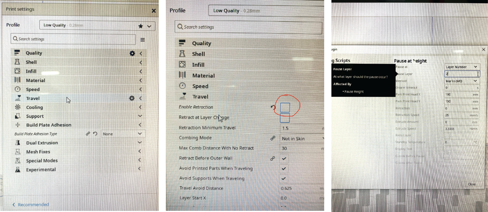
Step 3 – The model is then run through the program UltiMaker Cura, that generates information for height, amount, density and other important properties of layers, as well as the timing of the printing process in a G-code form.


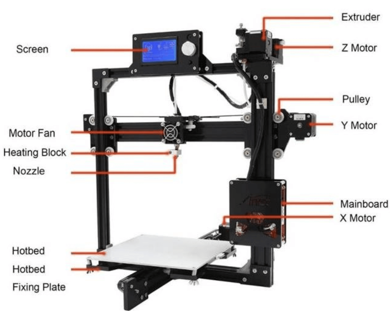
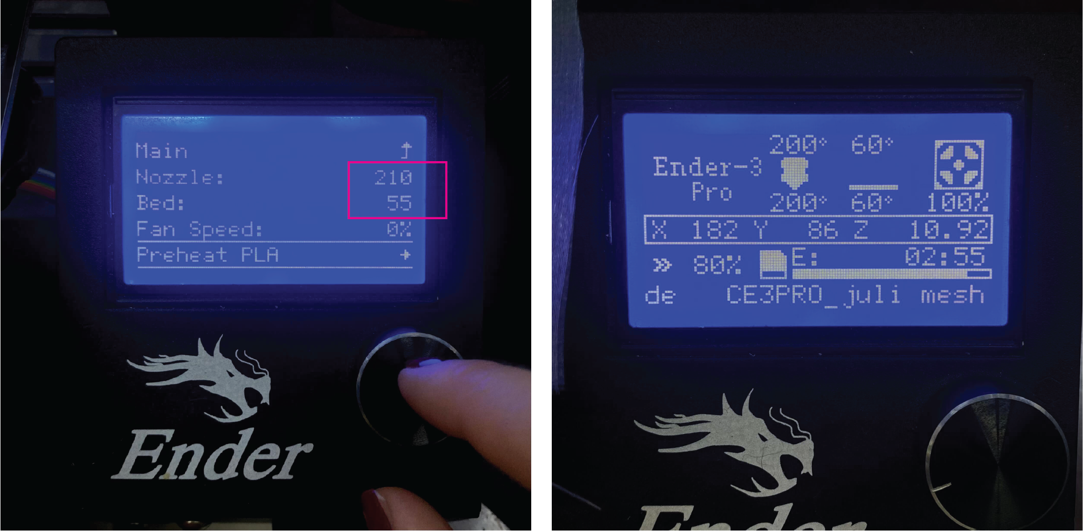
Step 4 – To prepare for printing, we need to prepare the printing bed and nozzle. In this case, we heated up the nozzle to 210 degrees. The temperature of the nozzle will depend on the printing material and the design being printed. For more information on this topic, you can refer to the 3D materials section.
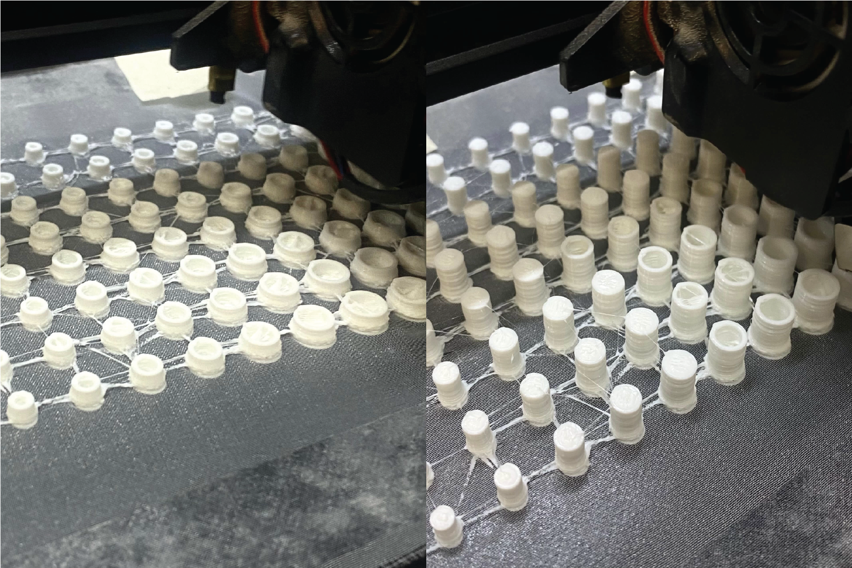
Step 5 – First layer is printed on the bed. Then printing is paused. photo
Step 6 – I carefully placed the fabric on the bed and secured the organza with tape to keep it still. It's important to be cautious of where the nozzle ends up during this step. You can control the nozzle's movement using the M17 function in the UltiMaker Cura program. This command activates the stepper motors on a 3D printer during the printing process.
Step 7 – Start the printing again.
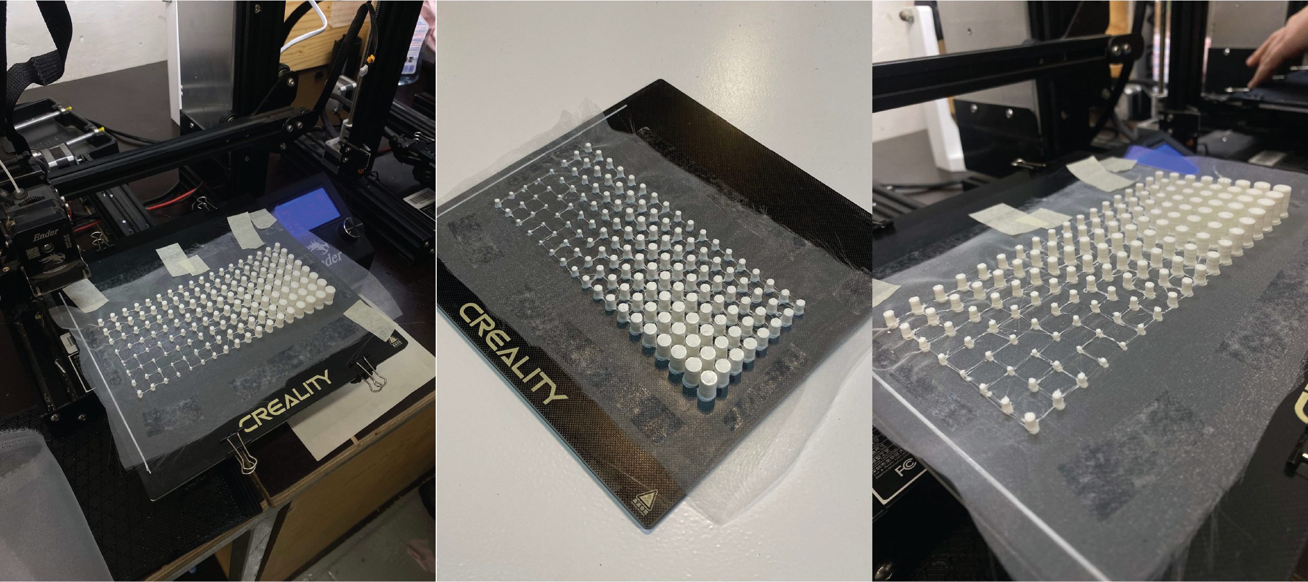
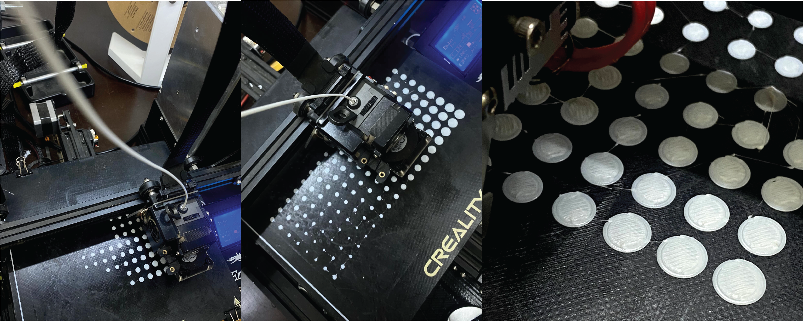
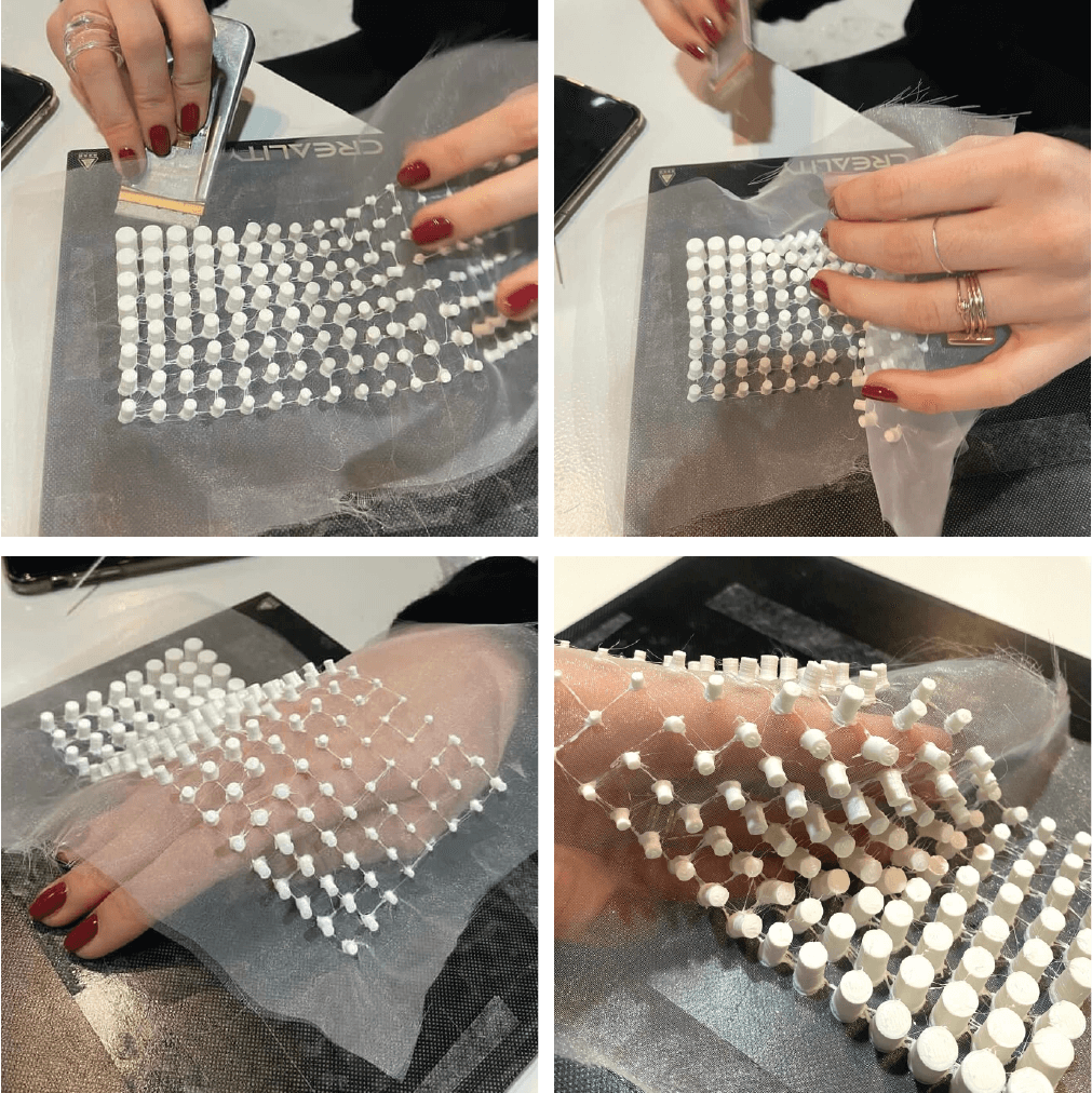
Step 8 – It was quite challenging to detach the design from the printing bed once it was finished. Slowly and with patience I managed to get the fabric of the bed.

Final outcome


Conclusions
I would love to learn and explore more about parametric design and working with Grasshopper language. It was an interseting journey! Although I for sure can't say that I fully understand it yet, I am proud that I was able to navigate it to some extent and achieve a good result in the end. Additionally, I would also love to explore, try working with 3D bioprinting in the near future!
:)