12. Skin Electronics
weekly assignment
Learning outcomes
- Research skills: the participant has acquired knowledge through references and concept development
- Design skills: the participant learnt to program a microcontroller, design circuit and schematic
- Fabrication skills: the participant is able of integrating inputs and outputs in a microcontroller project
- Process skills: Anyone can go through the process, understand it and reproduce it
- Final outcome: Is the assignment is assembled, functioning or tested
- Originality: Has the design been thought through and elaborated?
Student checklist
- Document the concept, sketches, references also to artistic and scientific publications
- Design a “skin-circuit”, exploring the replication of the examples below or:
- the Skin masquerade party project
- the Twinkle Nails project
- interactive tattoo
- explore how to create a new skin electronics accessory
- Document the project and included all source files and all materials used
- Upload your design files and source code
- Make a video with your skin electronic working
- Make a short performance/concept of your project functioning (extra credit)
This week I went full insanity and charlieplexed 30 SMD l.e.d.s with an ATtiny. I was really inspired by this week's lecture to create a circuit on my skin with tiny tiny l.e.d's that would resemble piercings or futuristic makeup.
during my research phase, i was really inspired by Anna Cain's reserch and references. she mentioned the star acne patches and how they are medicinally beneficial to skin health but also cute enough to be accessorized by its user. she went on to create a flower patch that would be used to record body temperature at a certain time each morning to track menstrual health. this would then save her the energy and pressure of having to wake up at the same time everyday to track her temperature. she goes into how there is an existing ring or watch technology out there that functions similarly but the data that it records can sometimes fall into dangerous hands, and that she was curious to make her own diy project.
this week, i did not make anything near a life-changing electronic device that could follow me and my body no matter where i go.
i thought of skin + electronics. and perhaps not enough skinelectronics. I focused on aesthetics and decoration. i thought of these photos of piercings that i saw on the door of a piercing shop in tokyo, and i wanted to recreate something like this for my assignment this week.


it was helpful to brainstorm with the definitions we came up with during our lecture to the question: what is skin to you?
for me, skin is both a protective membrane (it IS the largest organ) as well as one of the ways we can be most vulnerable (no defense or armour).
the image of the piercings reminded be of this dichotomy: tough and soft. scary and sweet. what better way of honoring the skin we live in than to ornament and adorn it.
this week i chose to fake piercings with smd leds in the shape of a Star, casted in Ecoflex. at first i lined up approx 50 leds in the shape of a star, only to realise that if i were to connect each of them to a circuit i was going to need to stack up to 50? 3V batteries onto my body (considering each led requires 3v to light up). which would have apparently been lethal. as a result, charlieplexing came into the picture.
references & inspiration


tools
- ATtiny
- Arduino IDE
- MultiMeter
- TinkerCad
- smd leds
process and workflow
charlieplexing
learn more about Charlieplexing
put very very simple: charlieplexing is a technique for driving multiple LEDs with relatively few pins on a microcontroller.
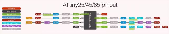
because i planned to use the ATtiny, which has 8 pins.. but technically 6 (-2 for the power and GND), i knew i had to max out at 30 leds for my star pattern.

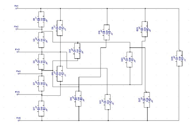
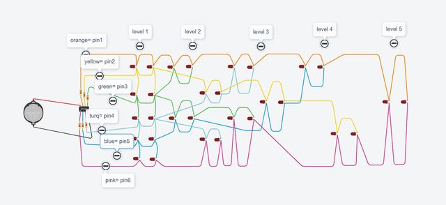
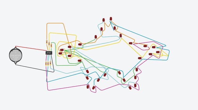
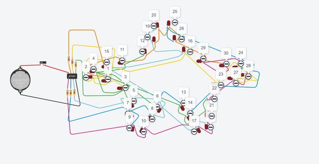
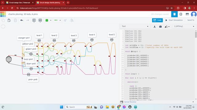
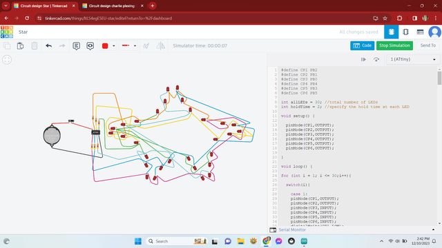
tinkercad
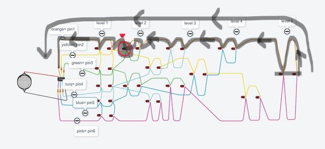
tinkercad was the best way i could think of to create my charlieplexing diagram for 30 leds and 6 pins, then to drag it into the shape i wanted
programming
before i put in all the effort to solder the leds together, i had to test that the code would work for the charlieplexing and the star arrangement, so with rico's help we wrote the code and put it into tinkercad. it went smoothly !
soldering (longest process)
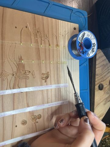
finally! time to solder
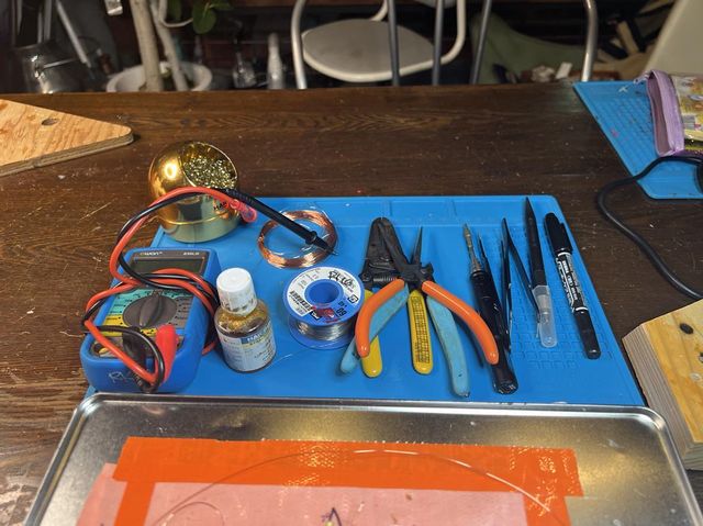
you'll need
- soldering iron
- solder
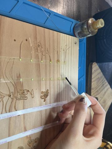
- flux
- brass wool to clean soldering iron
- smd leds
- tweezers
- multimeter
- polyurethane coated wire
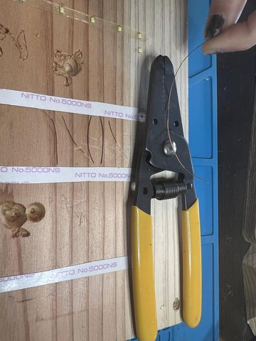
- snip wire
- scalp wire
- flux wire
- tin and solder wire to led
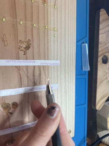
here i was trying to attach a wire strand to each led's positive side. we thought it'd be easier to spot the positive side of the led, but also to have less wire to solder onto the base of each led as some of them required up to 4 wires on one side.
soldering tips
- solder iron needs to touch both areas you're connecting
- allow solder to heat up each faces before connecting the two
- tinning is a process where you apply a bit of solder to the end of a wire
- check the connectivity with a multimeter after each soldering job
took me about 10 hours to solder all these wires together. then i added resistors to the end of each pin wire and then to the base of the ATtiny.
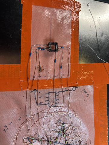
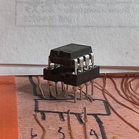
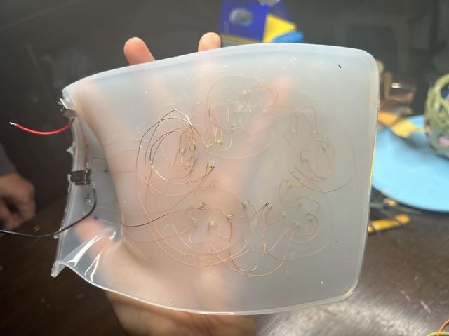
here is what the base of the ATtiny is like. it is raised platform so that when i cast it in the ecoflex, it can remain above and I can remove it to change the program
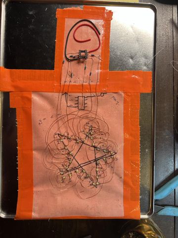
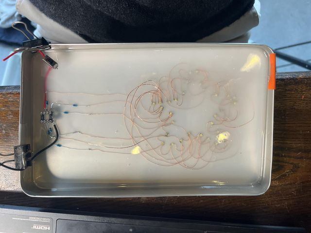
finally i removed it from my trusty sticky-side-of-the-tape workplace and it remained in its beautiful star shape
troubleshooting
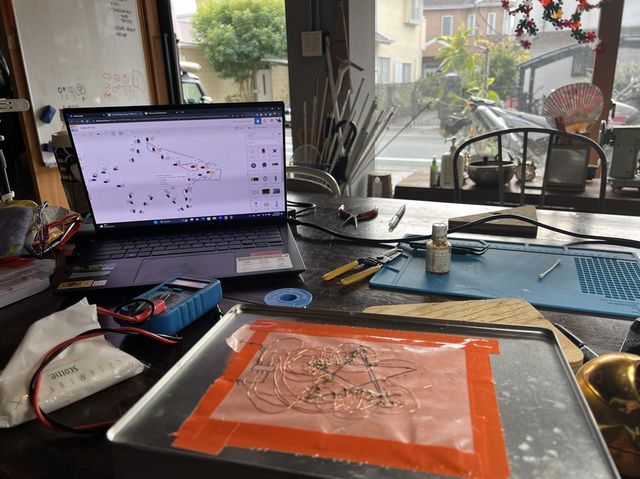
next, i had to check if the circuit had any errors. to do this we used a power box to connect each ATtiny pin wire to a power (+) and a gnd (-). there were a couple errors when we first tried this...
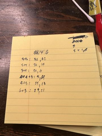
some pin connections would light up 2 leds instead of one. some connections wouldn't light at all. so rico and i made a list of the ones that didn't work and we saw a pattern. most of the pairs were affected. to troubleshoot we started at the furthest led connecion (led 30) and revisited all its connections to other leds before returning to it's orginal pin. by doing this we discovered that at one led, i had soldered the wire to the positive side instead of the negative side. fortunately, changing this wiring fixed the rest of the problems..... ** big sigh of relief **
we tested every pin combination to see if all 30 led would light up individually. all 30 leds lit up
testing each pin connectection:

casting in ecoflex
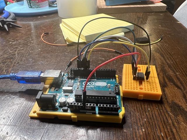
attiny programming
steps:
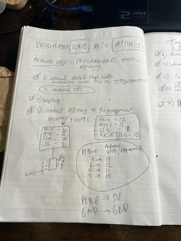

wiring:
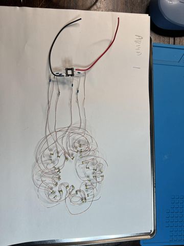
adding battery
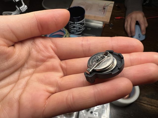
i used two 3v batteries
code for charlieplexing 30 leds with 6 pins
    #define CP1 PB2
    #define CP2 PB1
    #define CP3 PB0
    #define CP4 PB4
    #define CP5 PB3
    #define CP6 PB5

    int allLEDs = 30; //total number of LEDs
    int holdTime = 20; //specify the hold time at each LED

    void setup() {

    pinMode(CP1,OUTPUT);
    pinMode(CP2,OUTPUT);
    pinMode(CP3,OUTPUT);
    pinMode(CP4,OUTPUT);
    pinMode(CP5,OUTPUT);
    pinMode(CP6,OUTPUT);

    }

    void loop() {

    for (int i = 1; i <= 20;i++){

    switch(i){

        case 1:
        pinMode(CP1,OUTPUT);
        pinMode(CP2,OUTPUT);
        pinMode(CP3,INPUT);
        pinMode(CP4,INPUT);
        pinMode(CP5,INPUT);
        pinMode(CP6,INPUT);
        digitalWrite(CP1,LOW);
        digitalWrite(CP2,HIGH);
        delay(holdTime);
        break;

        case 2:
        pinMode(CP1,OUTPUT);
        pinMode(CP2,OUTPUT);
        pinMode(CP3,INPUT);
        pinMode(CP4,INPUT);
        pinMode(CP5,INPUT);
        pinMode(CP6,INPUT);
        digitalWrite(CP1,HIGH);
        digitalWrite(CP2,LOW);
        delay(holdTime);
        break;

        case 3:
        pinMode(CP1,INPUT);
        pinMode(CP2,OUTPUT);
        pinMode(CP3,OUTPUT);
        pinMode(CP4,INPUT);
        pinMode(CP5,INPUT);
        pinMode(CP6,INPUT);
        digitalWrite(CP2,LOW);
        digitalWrite(CP3,HIGH);
        delay(holdTime);
        break;

        case 4:
        pinMode(CP1,INPUT);
        pinMode(CP2,OUTPUT);
        pinMode(CP3,OUTPUT);
        pinMode(CP4,INPUT);
        pinMode(CP5,INPUT);
        pinMode(CP6,INPUT);
        digitalWrite(CP2,HIGH);
        digitalWrite(CP3,LOW);
        delay(holdTime);
        break;

        case 5:
        pinMode(CP1,INPUT);
        pinMode(CP2,INPUT);
        pinMode(CP3,OUTPUT);
        pinMode(CP4,OUTPUT);
        pinMode(CP5,INPUT);
        pinMode(CP6,INPUT);
        digitalWrite(CP3,LOW);
        digitalWrite(CP4,HIGH);
        delay(holdTime);
        break;

        case 6:
        pinMode(CP1,INPUT);
        pinMode(CP2,INPUT);
        pinMode(CP3,OUTPUT);
        pinMode(CP4,OUTPUT);
        pinMode(CP5,INPUT);
        pinMode(CP6,INPUT);
        digitalWrite(CP3,HIGH);
        digitalWrite(CP4,LOW);
        delay(holdTime);
        break;

        case 7:
        pinMode(CP1,INPUT);
        pinMode(CP2,INPUT);
        pinMode(CP3,INPUT);
        pinMode(CP4,OUTPUT);
        pinMode(CP5,OUTPUT);
        pinMode(CP6,INPUT);
        digitalWrite(CP4,LOW);
        digitalWrite(CP5,HIGH);
        delay(holdTime);
        break;

        case 8:
        pinMode(CP1,INPUT);
        pinMode(CP2,INPUT);
        pinMode(CP3,INPUT);
        pinMode(CP4,OUTPUT);
        pinMode(CP5,OUTPUT);
        pinMode(CP6,INPUT);
        digitalWrite(CP4,HIGH);
        digitalWrite(CP5,LOW);
        delay(holdTime);
        break;

        case 9:
        pinMode(CP1,INPUT);
        pinMode(CP2,INPUT);
        pinMode(CP3,INPUT);
        pinMode(CP4,INPUT);
        pinMode(CP5,OUTPUT);
        pinMode(CP6,OUTPUT);
        digitalWrite(CP5,LOW);
        digitalWrite(CP6,HIGH);
        delay(holdTime);
        break;

        case 10:
        pinMode(CP1,INPUT);
        pinMode(CP2,INPUT);
        pinMode(CP3,INPUT);
        pinMode(CP4,INPUT);
        pinMode(CP5,OUTPUT);
        pinMode(CP6,OUTPUT);
        digitalWrite(CP5,HIGH);
        digitalWrite(CP6,LOW);
        delay(holdTime);
        break;

        case 11:
        pinMode(CP1,OUTPUT);
        pinMode(CP2,INPUT);
        pinMode(CP3,OUTPUT);
        pinMode(CP4,INPUT);
        pinMode(CP5,INPUT);
        pinMode(CP6,INPUT);
        digitalWrite(CP1,LOW);
        digitalWrite(CP3,HIGH);
        delay(holdTime);
        break;

        case 12:
        pinMode(CP1,OUTPUT);
        pinMode(CP2,INPUT);
        pinMode(CP3,OUTPUT);
        pinMode(CP4,INPUT);
        pinMode(CP5,INPUT);
        pinMode(CP6,INPUT);
        digitalWrite(CP1,HIGH);
        digitalWrite(CP3,LOW);
        delay(holdTime);
        break;

        case 13:
        pinMode(CP1,INPUT);
        pinMode(CP2,INPUT);
        pinMode(CP3,OUTPUT);
        pinMode(CP4,INPUT);
        pinMode(CP5,OUTPUT);
        pinMode(CP6,INPUT);
        digitalWrite(CP3,LOW);
        digitalWrite(CP5,HIGH);
        delay(holdTime);
        break;

        case 14:
        pinMode(CP1,INPUT);
        pinMode(CP2,INPUT);
        pinMode(CP3,OUTPUT);
        pinMode(CP4,INPUT);
        pinMode(CP5,OUTPUT);
        pinMode(CP6,INPUT);
        digitalWrite(CP3,HIGH);
        digitalWrite(CP5,LOW);
        delay(holdTime);
        break;

        case 15:
        pinMode(CP1,INPUT);
        pinMode(CP2,OUTPUT);
        pinMode(CP3,INPUT);
        pinMode(CP4,OUTPUT);
        pinMode(CP5,INPUT);
        pinMode(CP6,INPUT);
        digitalWrite(CP2,LOW);
        digitalWrite(CP4,HIGH);
        delay(holdTime);
        break;

        case 16:
        pinMode(CP1,INPUT);
        pinMode(CP2,OUTPUT);
        pinMode(CP3,INPUT);
        pinMode(CP4,OUTPUT);
        pinMode(CP5,INPUT);
        pinMode(CP6,INPUT);
        digitalWrite(CP2,HIGH);
        digitalWrite(CP4,LOW);
        delay(holdTime);
        break;

        case 17:
        pinMode(CP1,INPUT);
        pinMode(CP2,INPUT);
        pinMode(CP3,INPUT);
        pinMode(CP4,OUTPUT);
        pinMode(CP5,INPUT);
        pinMode(CP6,OUTPUT);
        digitalWrite(CP4,LOW);
        digitalWrite(CP6,HIGH);
        delay(holdTime);
        break;

        case 18:
        pinMode(CP1,INPUT);
        pinMode(CP2,INPUT);
        pinMode(CP3,INPUT);
        pinMode(CP4,OUTPUT);
        pinMode(CP5,INPUT);
        pinMode(CP6,OUTPUT);
        digitalWrite(CP4,HIGH);
        digitalWrite(CP6,LOW);
        delay(holdTime);
        break;

        case 19:
        pinMode(CP1,OUTPUT);
        pinMode(CP4,OUTPUT);
        pinMode(CP2,INPUT);
        pinMode(CP3,INPUT);
        pinMode(CP5,INPUT);
        pinMode(CP6,INPUT);
        digitalWrite(CP4,HIGH);
        digitalWrite(CP1,LOW);
        delay(holdTime);
        break;

        case 20:
        pinMode(CP1,OUTPUT);
        pinMode(CP4,OUTPUT);
        pinMode(CP2,INPUT);
        pinMode(CP3,INPUT);
        pinMode(CP5,INPUT);
        pinMode(CP6,INPUT);
        digitalWrite(CP1,HIGH);
        digitalWrite(CP4,LOW);
        delay(holdTime);
        break;

        case 21:
        pinMode(CP3,OUTPUT);
        pinMode(CP6,OUTPUT);
        pinMode(CP2,INPUT);
        pinMode(CP1,INPUT);
        pinMode(CP5,INPUT);
        pinMode(CP4,INPUT);
        digitalWrite(CP6,HIGH);
        digitalWrite(CP3,LOW);
        delay(holdTime);
        break;

        case 22:
        pinMode(CP3,OUTPUT);
        pinMode(CP6,OUTPUT);
        pinMode(CP2,INPUT);
        pinMode(CP1,INPUT);
        pinMode(CP5,INPUT);
        pinMode(CP4,INPUT);
        digitalWrite(CP3,HIGH);
        digitalWrite(CP6,LOW);
        delay(holdTime);
        break;

        case 23:
        pinMode(CP2,OUTPUT);
        pinMode(CP5,OUTPUT);
        pinMode(CP6,INPUT);
        pinMode(CP1,INPUT);
        pinMode(CP3,INPUT);
        pinMode(CP4,INPUT);
        digitalWrite(CP5,HIGH);
        digitalWrite(CP2,LOW);
        delay(holdTime);
        break;

        case 24:
        pinMode(CP2,OUTPUT);
        pinMode(CP5,OUTPUT);
        pinMode(CP6,INPUT);
        pinMode(CP1,INPUT);
        pinMode(CP3,INPUT);
        pinMode(CP4,INPUT);
        digitalWrite(CP2,HIGH);
        digitalWrite(CP5,LOW);
        delay(holdTime);
        break;

        case 25:
        pinMode(CP1,OUTPUT);
        pinMode(CP5,OUTPUT);
        pinMode(CP6,INPUT);
        pinMode(CP2,INPUT);
        pinMode(CP3,INPUT);
        pinMode(CP4,INPUT);
        digitalWrite(CP5,HIGH);
        digitalWrite(CP1,LOW);
        delay(holdTime);
        break;

        case 26:
        pinMode(CP1,OUTPUT);
        pinMode(CP5,OUTPUT);
        pinMode(CP6,INPUT);
        pinMode(CP2,INPUT);
        pinMode(CP3,INPUT);
        pinMode(CP4,INPUT);
        digitalWrite(CP1,HIGH);
        digitalWrite(CP5,LOW);
        delay(holdTime);
        break;

        case 27:
        pinMode(CP2,OUTPUT);
        pinMode(CP6,OUTPUT);
        pinMode(CP5,INPUT);
        pinMode(CP1,INPUT);
        pinMode(CP3,INPUT);
        pinMode(CP4,INPUT);
        digitalWrite(CP6,HIGH);
        digitalWrite(CP2,LOW);
        delay(holdTime);
        break;

        case 28:
        pinMode(CP2,OUTPUT);
        pinMode(CP6,OUTPUT);
        pinMode(CP5,INPUT);
        pinMode(CP1,INPUT);
        pinMode(CP3,INPUT);
        pinMode(CP4,INPUT);
        digitalWrite(CP2,HIGH);
        digitalWrite(CP6,LOW);
        delay(holdTime);
        break;

        case 29:
        pinMode(CP1,OUTPUT);
        pinMode(CP6,OUTPUT);
        pinMode(CP5,INPUT);
        pinMode(CP2,INPUT);
        pinMode(CP3,INPUT);
        pinMode(CP4,INPUT);
        digitalWrite(CP6,HIGH);
        digitalWrite(CP1,LOW);
        delay(holdTime);
        break;

        case 30:
        pinMode(CP1,OUTPUT);
        pinMode(CP6,OUTPUT);
        pinMode(CP5,INPUT);
        pinMode(CP2,INPUT);
        pinMode(CP3,INPUT);
        pinMode(CP4,INPUT);
        digitalWrite(CP1,HIGH);
        digitalWrite(CP6,LOW);
        delay(holdTime);
        break;
    }

    }
    }
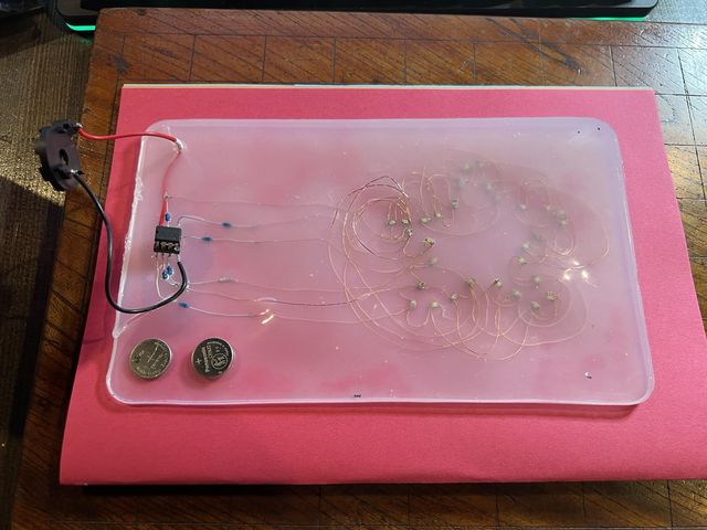
results
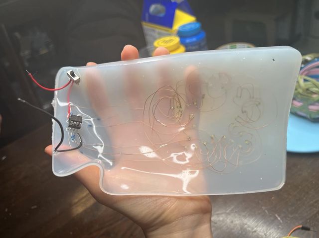
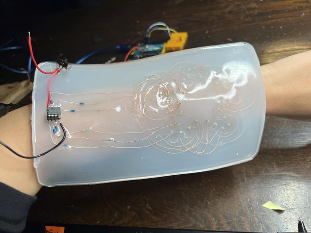
after casting the circuit into ecoflex... unfortunately something went wronog with some of the wires, and at times two leds would light up again instead of individually. some leds also didn't light up at all.. and i can't find out whether it was because
1. when i removed it from the orange tape, the connections got severed
2. the ecoflex tampered with some of the connections
3. either way, certain connections between the wires and leds were bothced n butchered . .
anyhow, you can still makeout the blinking star ⭐
reflections
- i wish i got a video of the program working on the leds before casting it into the ecoflex. to troubleshoot it once more (after i removed it from the sticky-side-of-the-tape workplace) -- because on the tape it was working beautifully!!
- working with electronics requires precision, delicateness, and meticulousness, it can be messed up really easily, so working slow is always better
- i'm still very happy with the results, after attaching all the leds, i only made one error in circuiting (soldering one of the wires to the led's negative side as opposed to the positive one) out of all 30 leds -with up to 4 wires on one side- i managed to get all of them correct except for one! -- which i, myself, am very impressed by
- soldering was like performing surgery, had to be very focused on a small spot and excercise a lot of control in small movements with your hands
- 6V (two 3V batteries) is still quite a high voltage for skin electronics -- rico joked my project was more skin-electrocution than it was skin electronics
- there was a lot more i could play around with in the programming as i managed to take up only 2kilobytes out of 8kb that the ATtiny can store. maybe light up the leds to go around the star in order, or play with the delays for each leds. playing with different color leds is another option, but perhaps too much brainwork for me in a week