13. Skin Electronics
INDEX IMAGE ~ human skin in the microscope
Research and Lecture
This week we are learning to use the body's physical features and functions as components in the electronic system: how can the body itself be an input, output or interface? We are studying Katia Vega´s Beauty Technology: a wearable computing subfield that integrates technology into cosmetics to be applied directly to one’s skin, fingernails and hair in order to transform the body’s surface in an interactive platform.
It is very important to make an ethical assessment of impact and think of implications: could this technology be used for control or harm? What would happen if millions of people had access? Where does the data go and who else could it be valuable for?
 This is a facinating video on how we could use design to expand the human Umwelt (German world for environment that means the unique percieved world of an organism). This may be done by sensory substitution (switching around the usual sensory experiences to create unexpected perceptions and drive new brain connections between senses). It is interesting to think of how skin electronics can play a role in expanding human perceptions to make us more intelligent? more compassionate? more healthy?
What comes to mind on the topic of skin? sensations, sensor, protection, membrane, filter One of my favorite quotes that addresses the subject of trascoorperality of the skin is:
“There are no discrete entities. As Paul Shepard describes it, the epidermis of the skin is, “ecologically like a pond surface or a forest soil, not a shell so much as a delicate interpenetration”
Neil Evernden. “Beyond Ecology: Self, Place and the Pathetic Fallacy.” The Ecocriticism Reader: Landmarks in Literary Ecology
Working with the skin it is important to remember it is a protective barrier for us and the environment but it is not an impenetrable wall. Our skin is always enganged in a dance of secretion and absorption and working on this membrane we must avoid toxic materials and prioritize comfort and health.
Electronics Notes
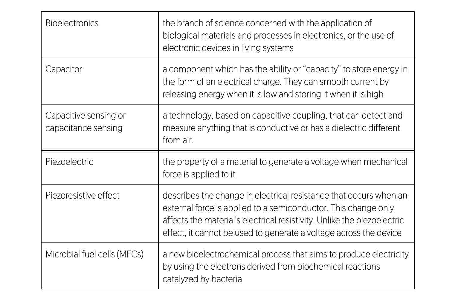
Capacitive Sensors
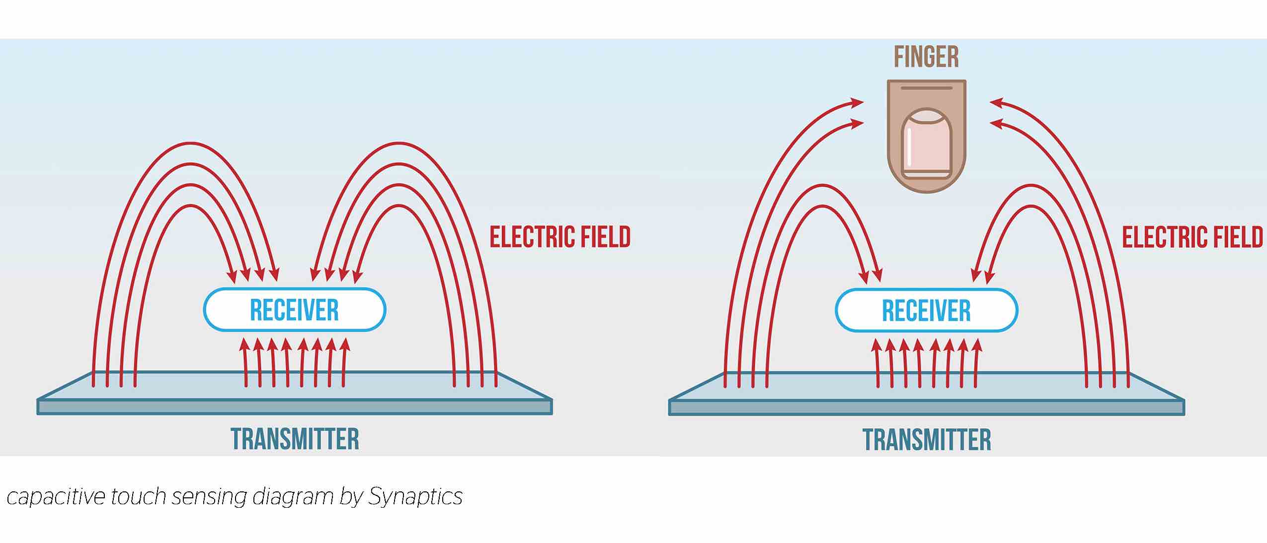
Capacitive sensors are devices that can detect the presence or absence of objects by using the electrical property of capacitance and the changes in the electrical field. They can be used to sense movement or action without contact (and even through materials like wood, plastic, ceramic, paint etc. so it could be concealed). (source)
- install the Capacity Sensor library
- using a feather board, all the pins that have the T have the ability to read capacitive sensors (T for touch)
- set a send pin and a recieve pin (sensor terminal) with a resistor in between. When the send pin changes state it will eventually change the recieve pin
- the delay in change is determined by an RC time constant (R * C, where R is the value of the resistor and C is the capacitance at the receive pin)
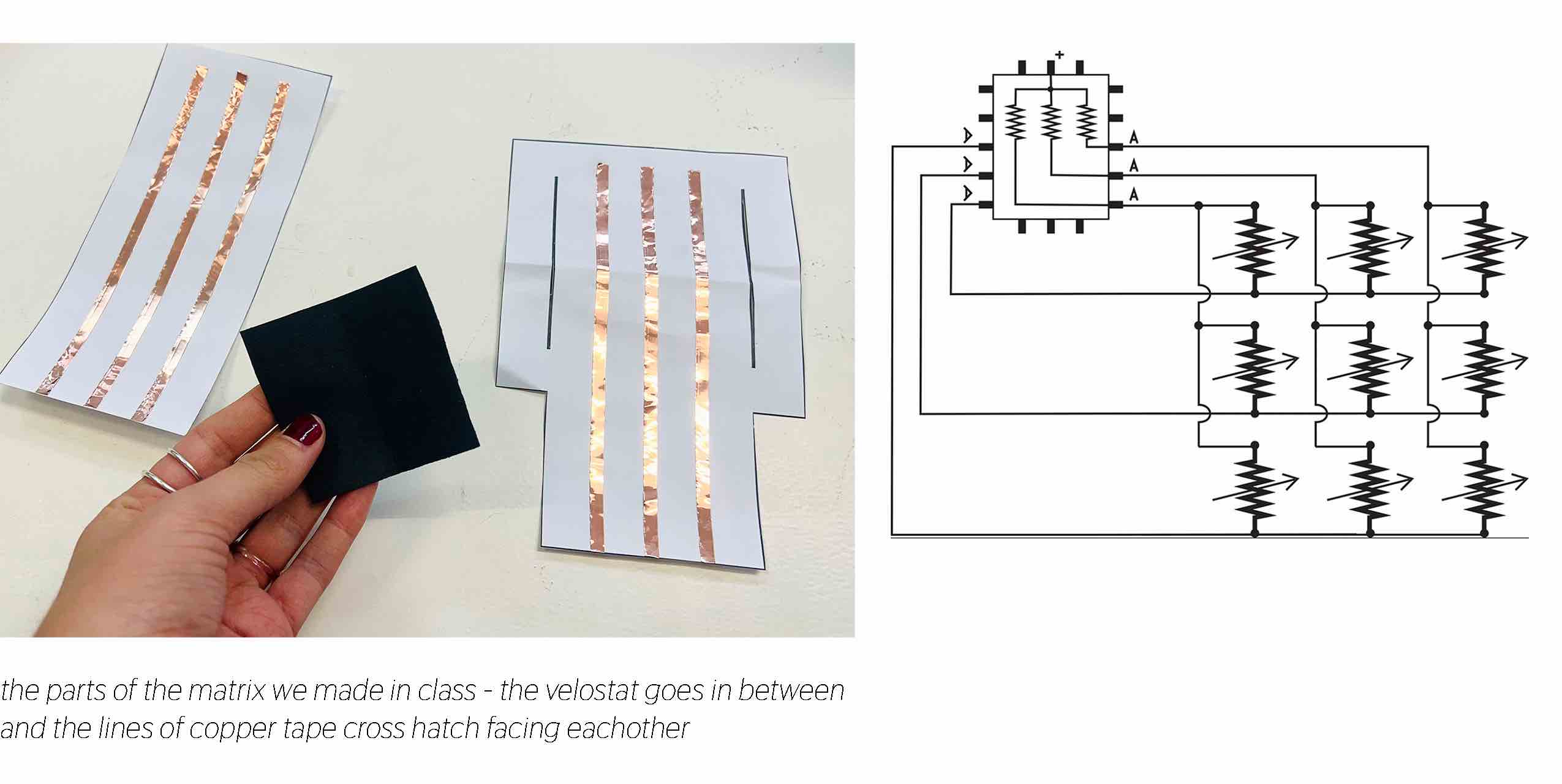
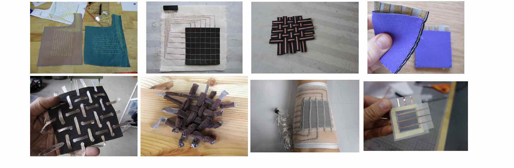
Pressure Matrix
a pressure matrix is made from a grid of conductive rows and columns with a piezoresistive material (Eeonyx, Velostat, conductive wool) in between. Use to map touch and pressure at each of the cross sections of the conductive threads.
- define the number or rows, colums and the sensor points (cross sections)
- use Matrix Processing to see grayscale outputs of pressing the sensor
- experiment with types of conductive materials and the ways they can be secured while in a grid
Skin Electronics for Menstruation Biohacking
For this week I am interested in how skin electronics could benefit menstruation health. I used to subscribe to Natural Cycles BBT (Basal Body Temperature) method for ovulation tracking to better understand my cycle and fertility days. I fell out of using it because I had to take my temperature every morning and write down the number right upon waking and it became kind of an annoying routine. To achieve proper data it is best to take the temp at the same time everyday and I would usually want to sleep in on the weekends.
I started thinking about a wearable thermometer that would be programmed to take the temp at a specific time each morning so the wearer would not have to do any work. Through my research I found basically this exact product - a wearable skin thermometer watch called Ava. But I still am curious to make a diy low tech version that could stand as a kind of accessible bio hack technology for menstruators. Topics of data privacy with period tracker apps became a hot topic with the anti-abortion legislation happening in the U.S. It would be great to be empowered to track our cycles without having to worry about apps selling the data or it becoming incriminating evidence in abortion cases. Ava complies with the General Data Protection Regulation (GDPR). Passed May 25, 2018 this is the toughest privacy and security law in the world. Though it was drafted and passed by the European Union (EU), it imposes obligations onto organizations anywhere, so long as they target or collect data related to people in the EU.
Understanding the Menstural and Hormonal Cycle
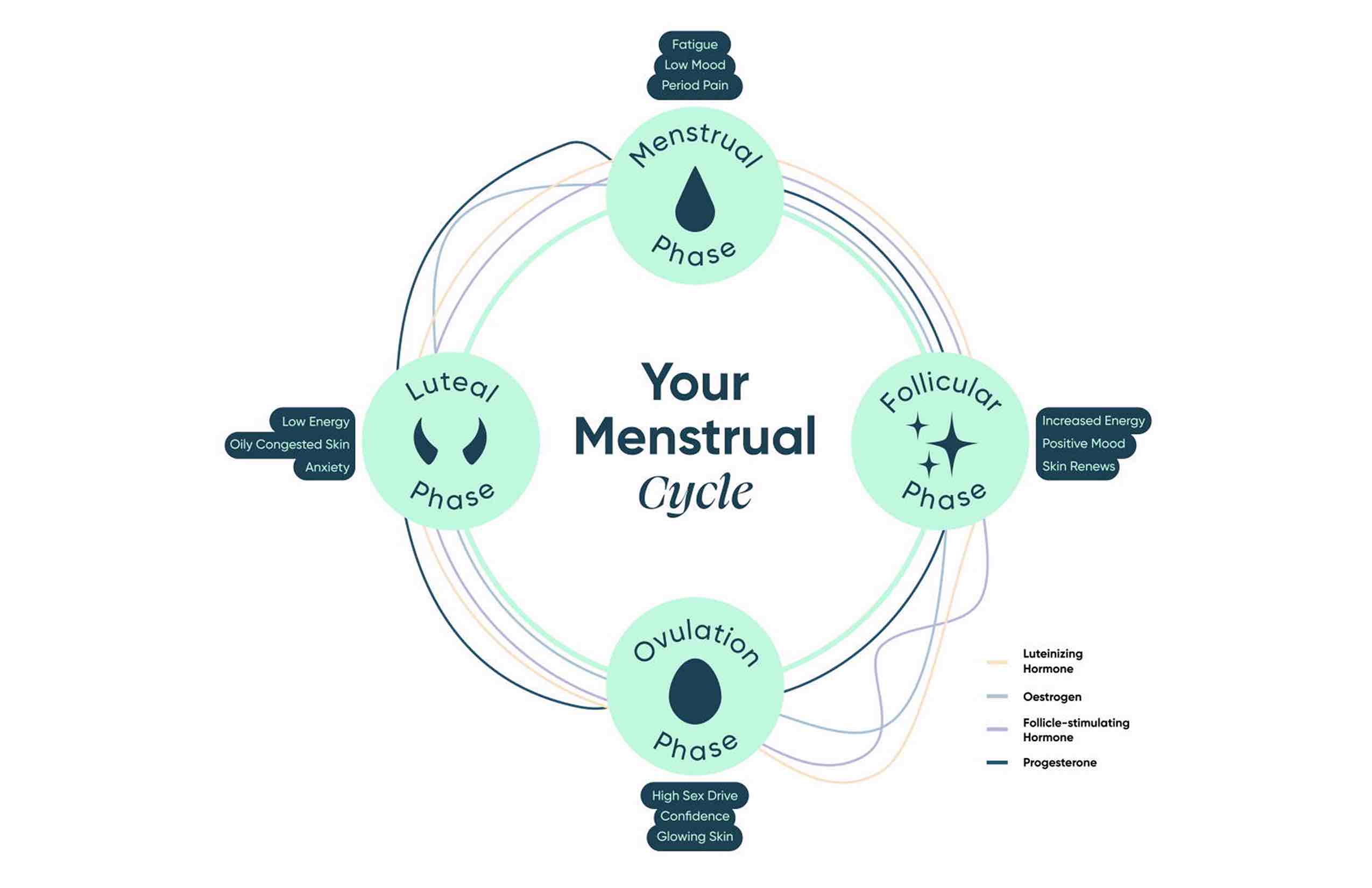 Reasons that it is helpful to know Ovulation time
- zinc and magnesium concentration hit lowest levels in the body during this time (it is good to take supplements to replenish) (source)
- ovulation reveals a fertile window if one is trying to conceive or to avoid it
- energy may be increased for social activities, hard workouts and having sex because of the hormonal changes
I'm even more passionate about designing a speculative version of a wearable thermometer that would utilize the new bacterial technology discovered at UMA (my last reference) What if a biofilm could create an output based on the input of our skin temperature? Maybe this does not include electronics and instead is a color or bioluminecesnt reaction that would inform the wearer of a temperature change?
References & Inspiration
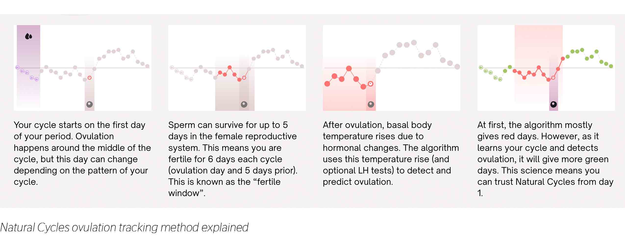
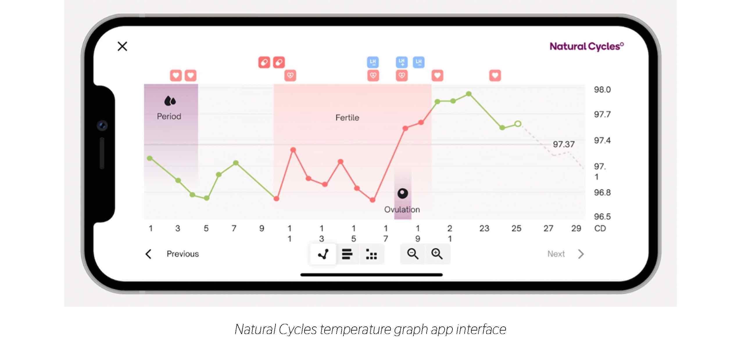
Natural Cycles BBT Ovulation Tracking
Natural Cycles is an app powered by an algorithm that determines your fertility status based on body temperature. They are considered a birth control method but based on reviews of people getting accidentally pregnant and how easy it is to make mistakes with this method, I think it is better as a way to track fertility days if you're trying to get pregnant. You take your temperature with an oral thermometer and log the data every morning and the app will reveal your fertile and non fertile days.
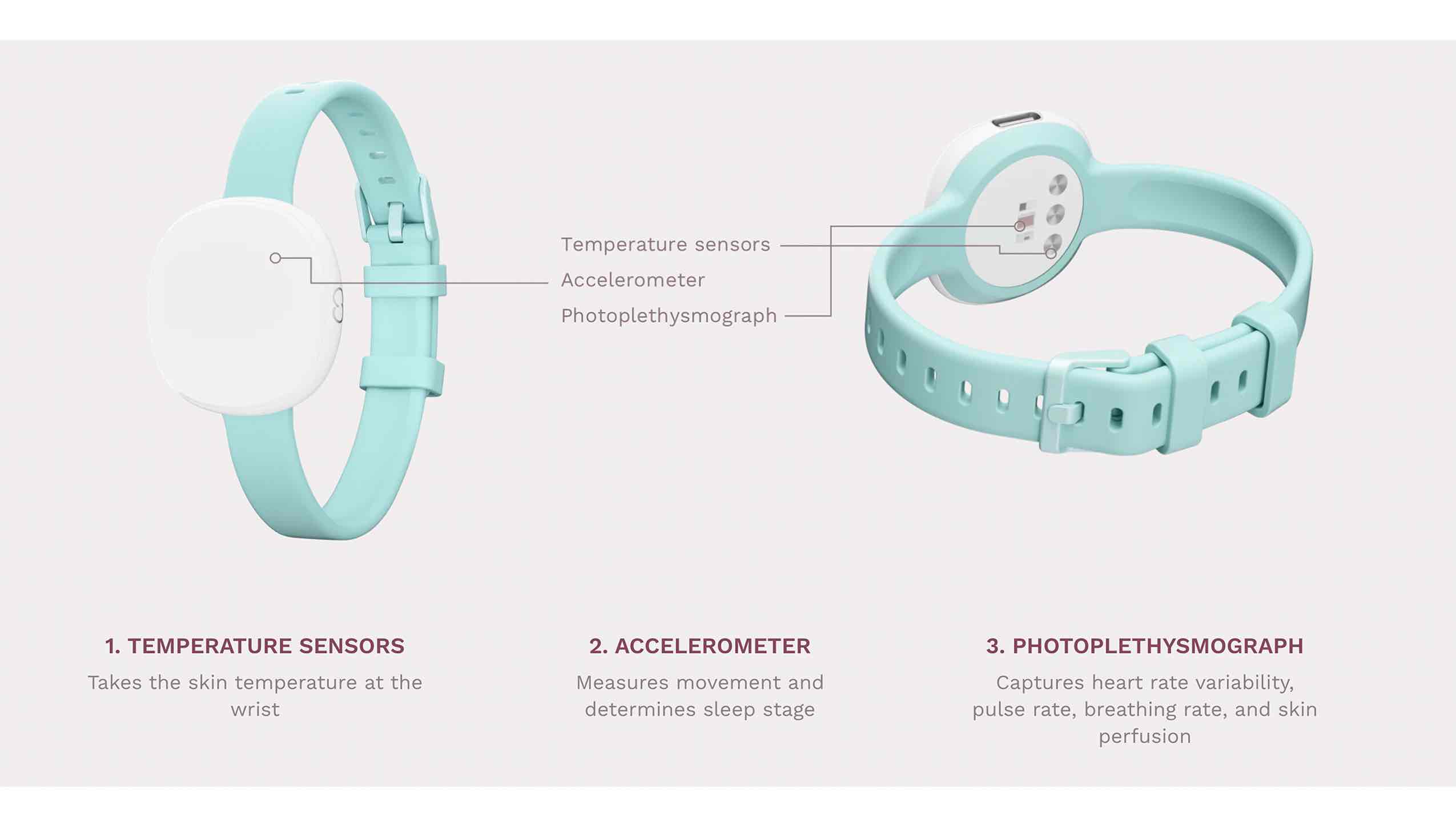
Ava Skin Temp Ovulation Tracking
Overnight, this Ava sensor bracelet collects continuous data and you sync it to your phone upon waking. I originally thought that BBT was the best way to track ovulation but they present studies that show wrist skin temperature was more sensitive than BBT in detecting ovulation, and increase of 0.50°C vs. 0.20°C. The device is mostly used for fertility tracking but it also measures and records data on temperature, sleep, physiological stress, and resting pulse rate.
Electronic "Tattoo" Thermometer
This thin flexible electronic By John Rogers at University of Illinois can monitor skin temperature with millikelvin precision. It is applied to the skin using a water-soluble glue. It can also provide a quantitative assessment of tissue thermal conductivity or be implemented in ways that reveal cardiovascular health information like constriction of blood vessels. (source)
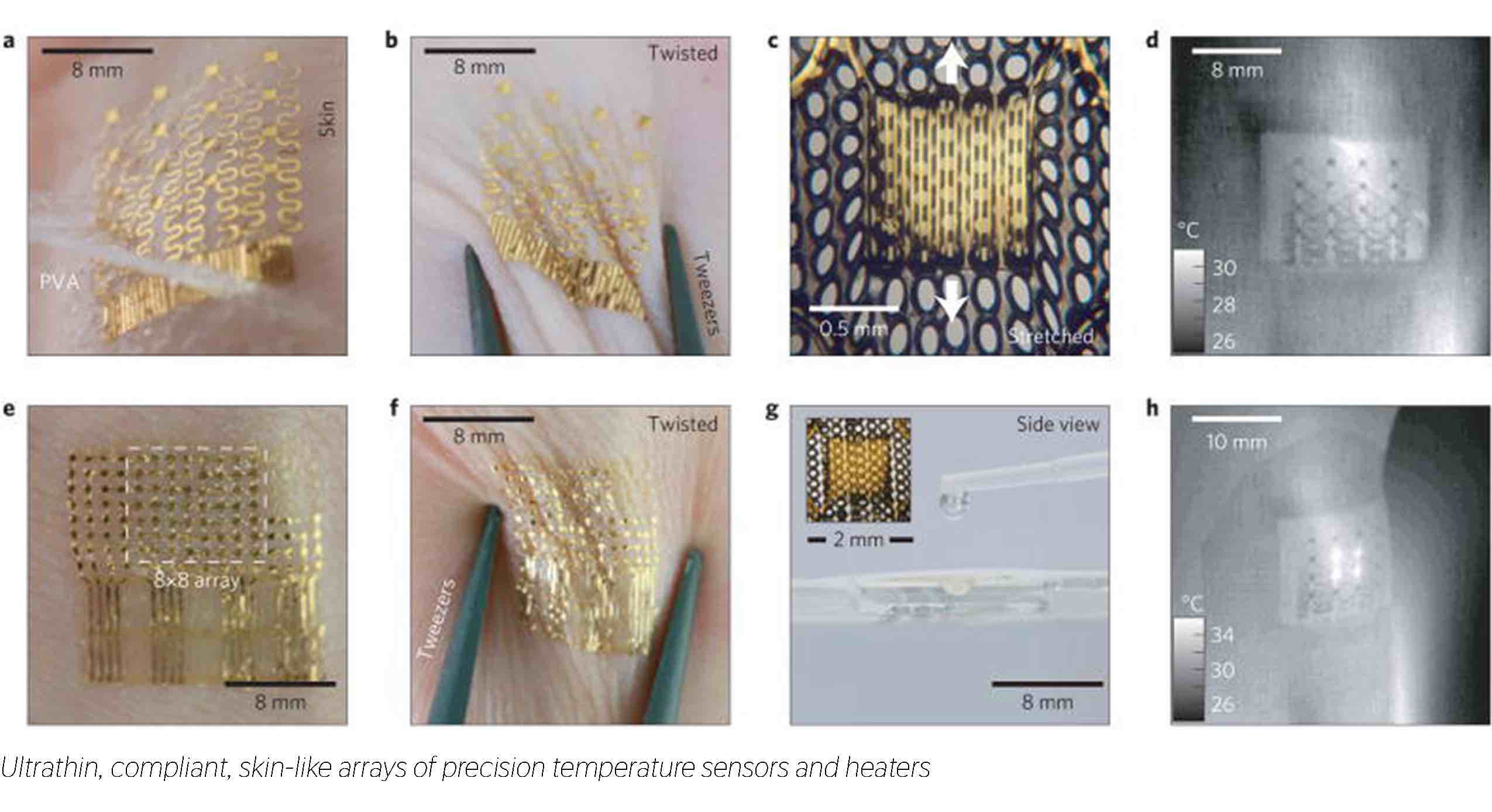
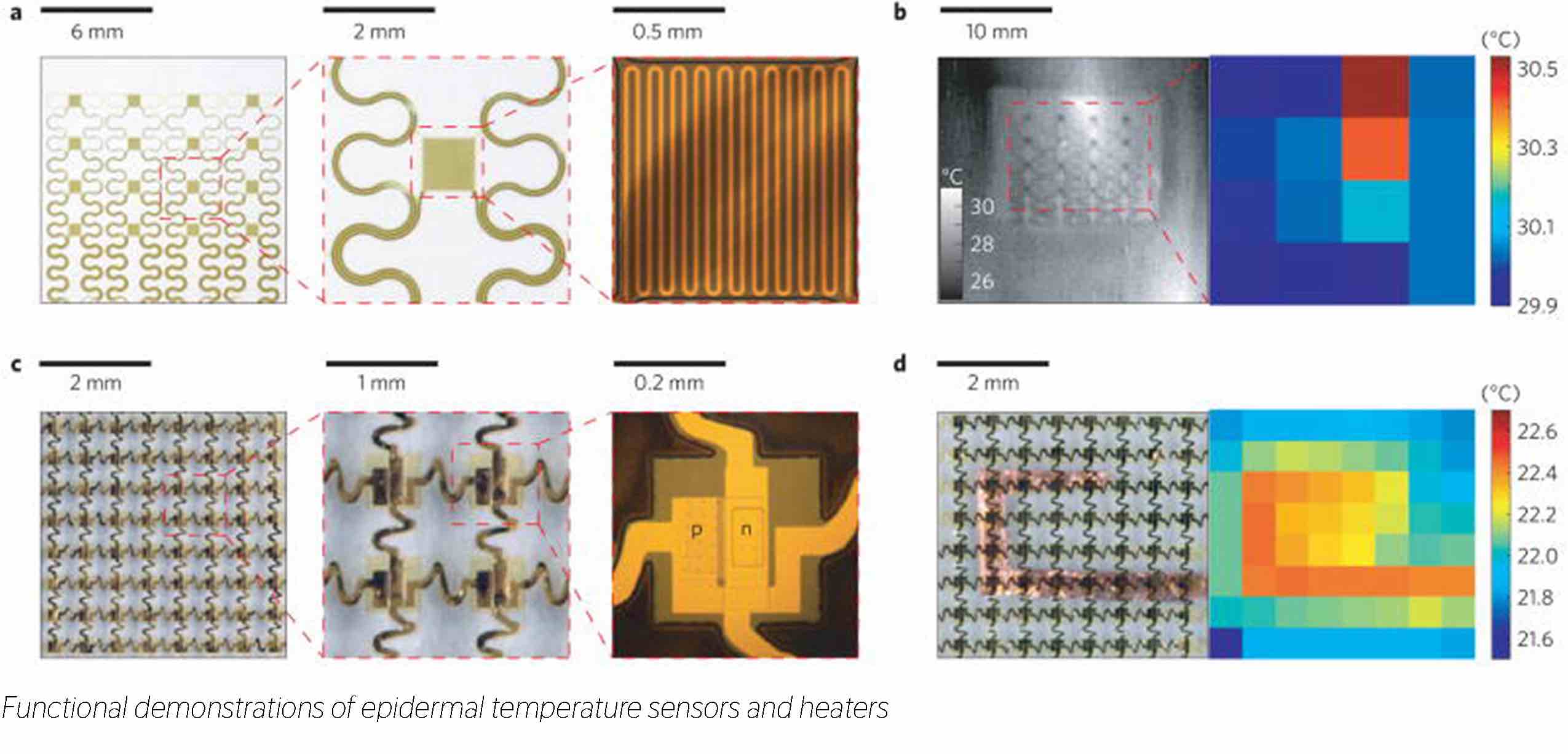
They microfabricated two patches: one with an array of temperature sensors that rely on the temperature coefficient of resistance (TCR) in thin (50 nm), narrow (20 μm) serpentine traces of gold, and another with multiplexed arrays of sensors based on PIN diodes formed by patterned doping of Si nanomembranes. The structures are covered with thin layers of polyimide (1.2 μm) for protection from moisture and electrical insulation.
"A key enabling characteristic for use on the skin is the ability to provide soft, conformal contact with the epidermis in a manner that does not constrain or alter natural motions or behaviours. This epidermal design enables robust adhesion with minimal irritation or discomfort, and without measurement artefacts that can arise from relative motion of the sensors/actuators and the skin or from interference with processes such as transdermal water loss" (source)
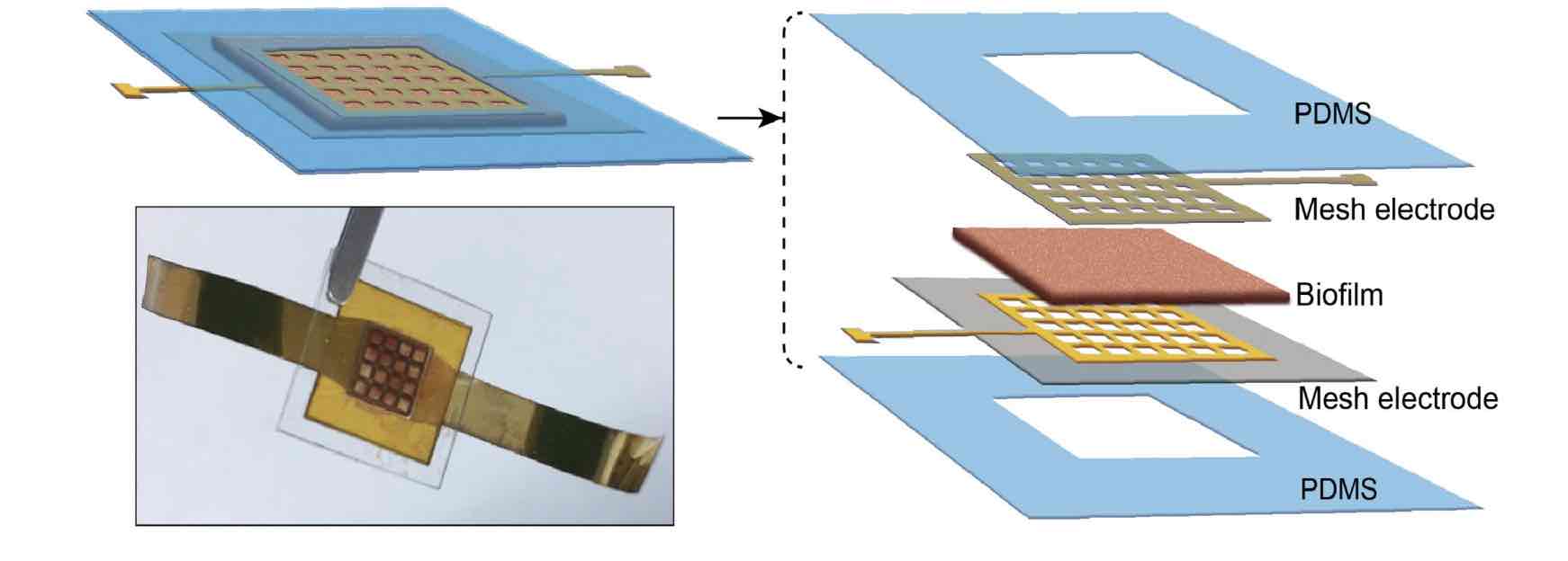
Biofilm "battery"
In August 2022 University of Massachusetts Amherst researchers invented a biofilm that can stick to the skin and harnesses sweat for electricity. The biofilm is made using the bacteria, Geobacter sulfurreducens, that converts energy from evaporation into electricity. In this wearable setting it utilizes one’s skin moisture turning into vapor to generate enough power for small devices like medical sensors or personal electronics.
Adafruit Wearable Temperature Monitor
Process and Workflow
Sketching
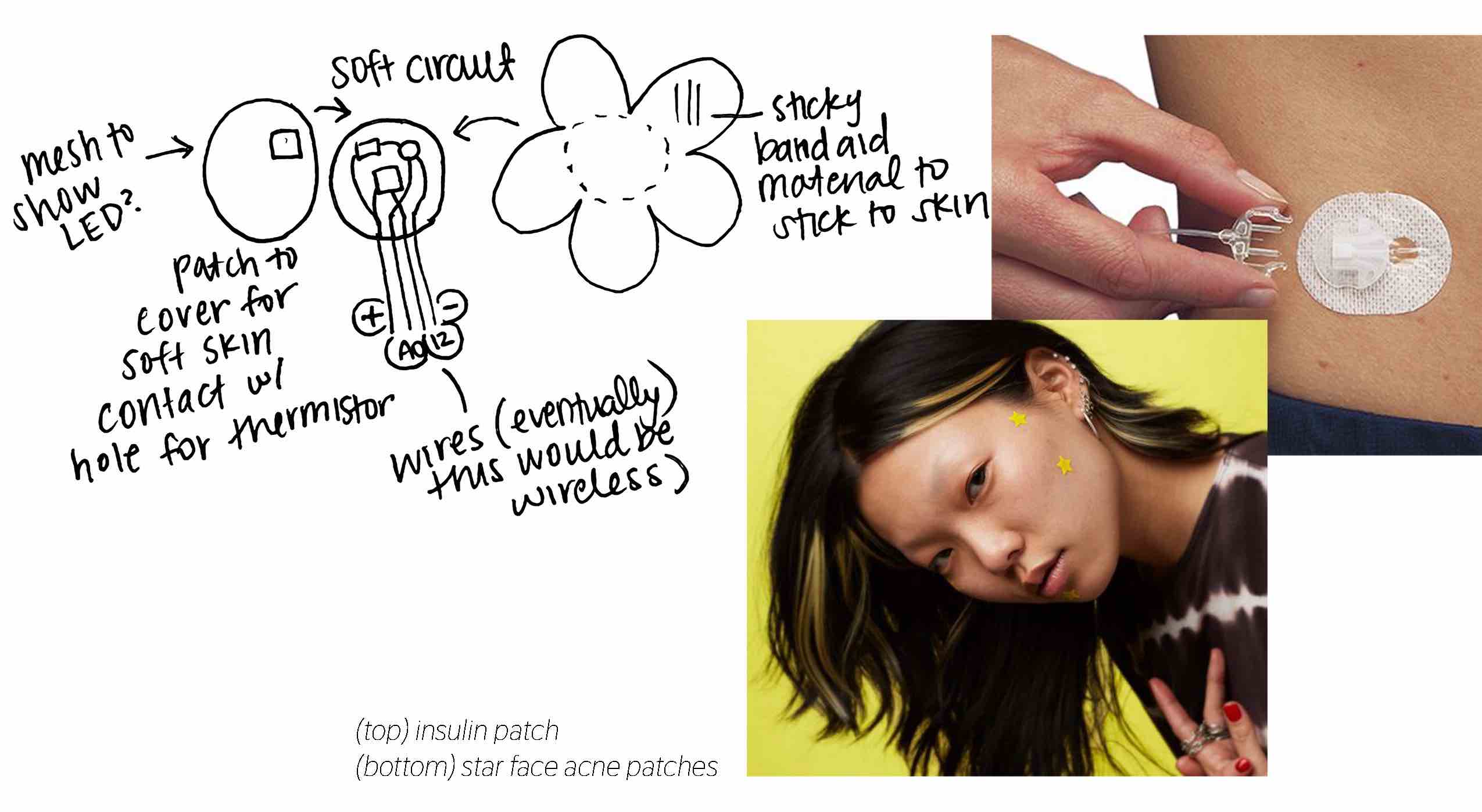
For my design I am imagining a simple wearable or patch with a thermistor to provide a quick response to signal the ovulation temperature spike. It will use a Thermistor to read the skin temperature and a neopixel led as an output. I chose to use the led because I want a small personal interaction only for the knowledge of the user without all of the data going to some app or algorithm.
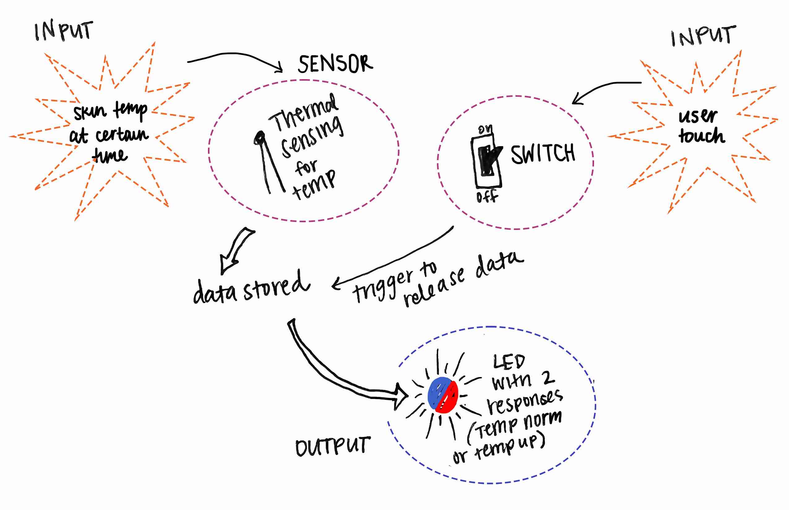 Ideally the device would be able to read the temperature in the morning while the user may still be sleeping and they could press a switch upon walking which would trigger the neopixel led to give a response based on the value taken earlier (blue if the temperature is at a normal level or red if it is spiked - signaling ovulation)
Testing the Thermoster
Thermistors are variable resistors that change their resistance with temperature. They are classified by the way their resistance responds to temperature changes. In Negative Temperature Coefficient (NTC) thermistors, resistance decreases with an increase in temperature. In Positive Temperature Coefficient (PTC) thermistors, resistance increases with an increase in temperature.
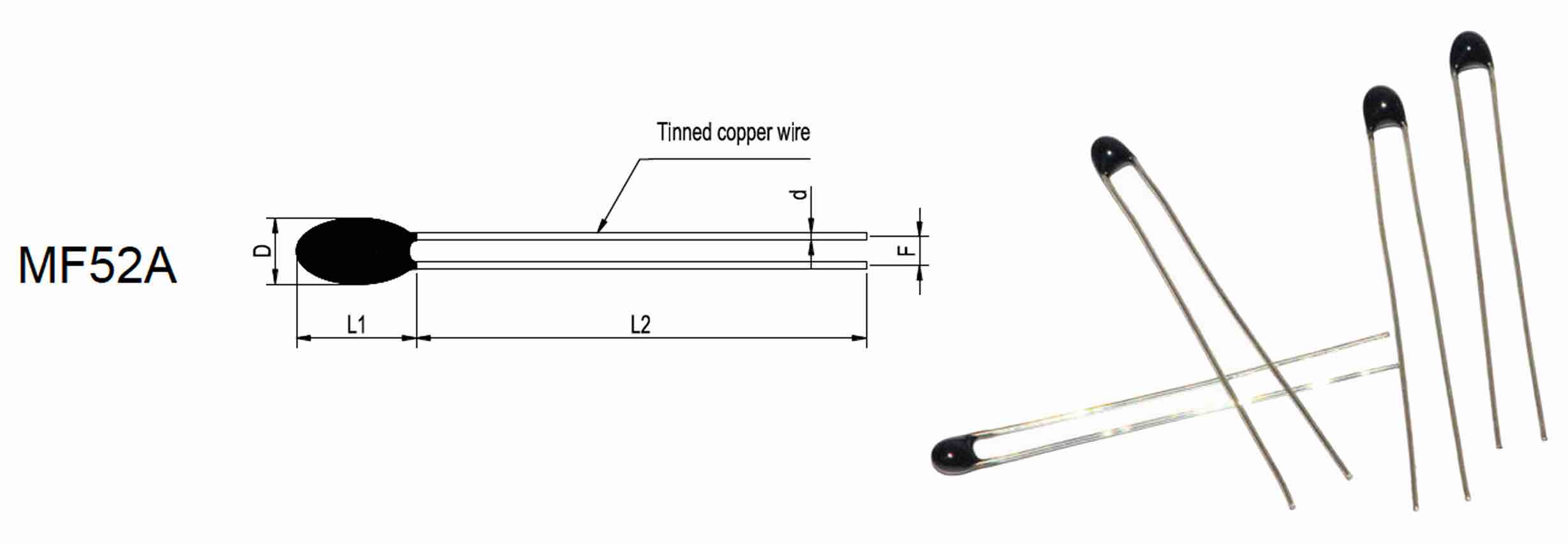
I am using an NTC thermistor. These are made from a semiconducting material (such as a metal oxide or ceramic) that’s been heated and compressed to form a temperature sensitive conducting material.
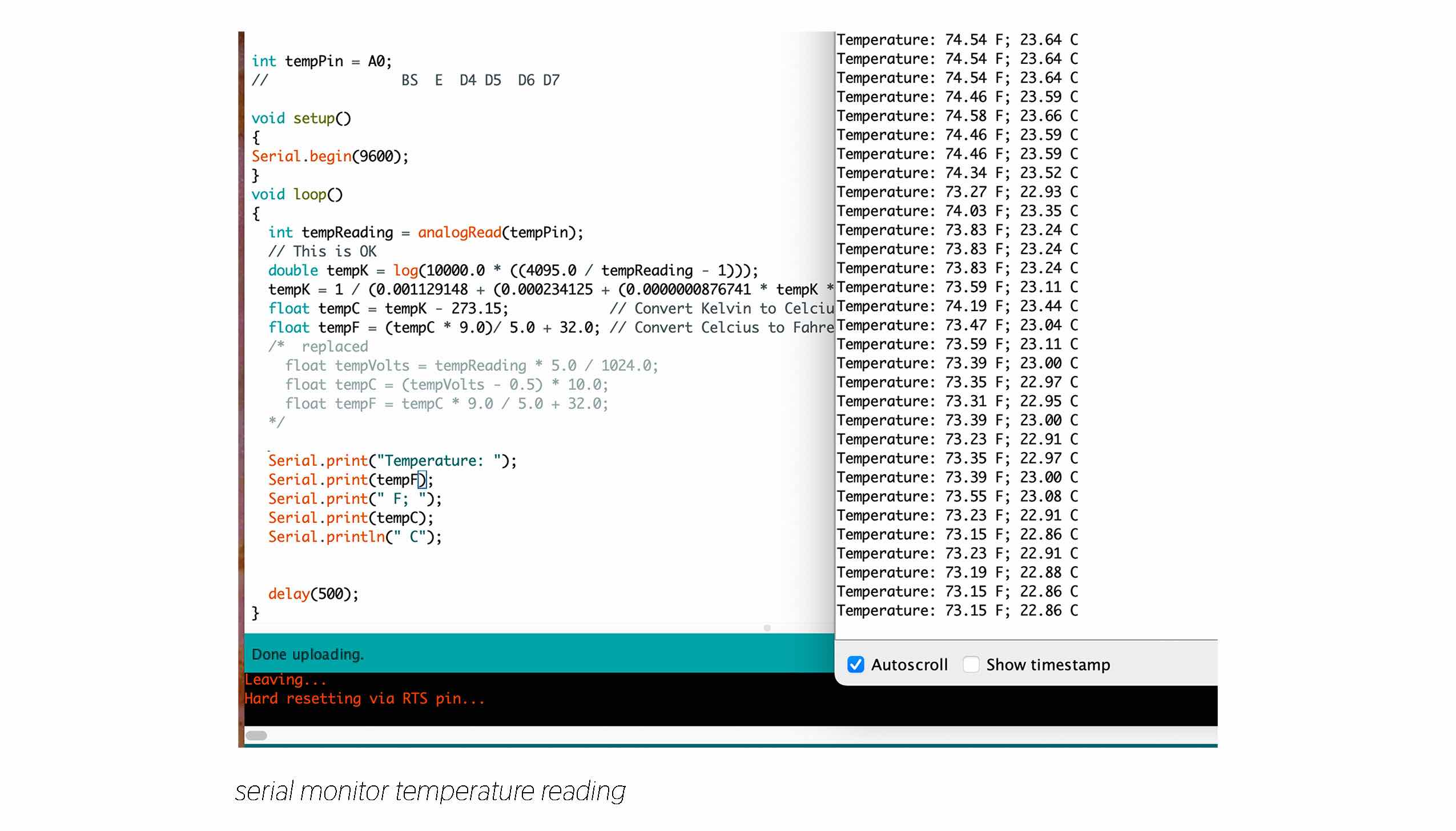
The Arduino will measure the voltage divider: the voltage at a point between the thermistor and a known resistor. Since my Thermistor is 10k I'm using a 10k resistor. Setting up the breadboard circuit for a basic test looks like this:
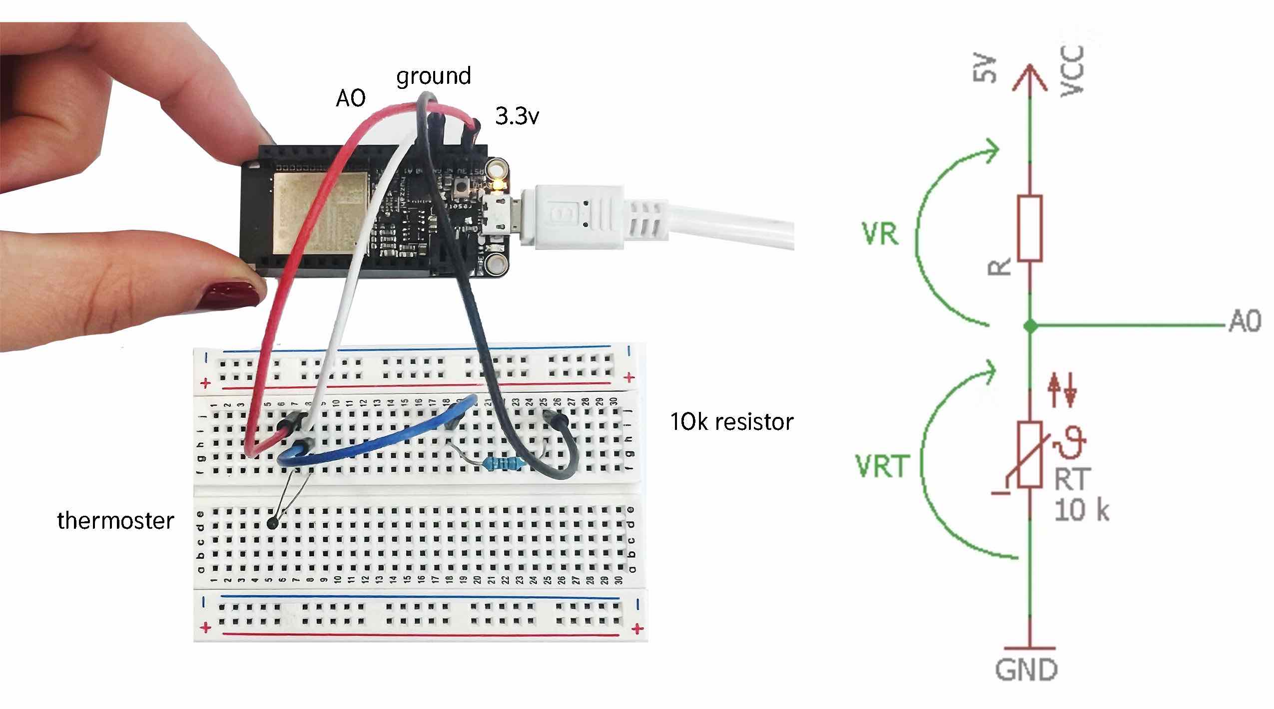
The number that this results in then needs to be calculated into a temperature value.
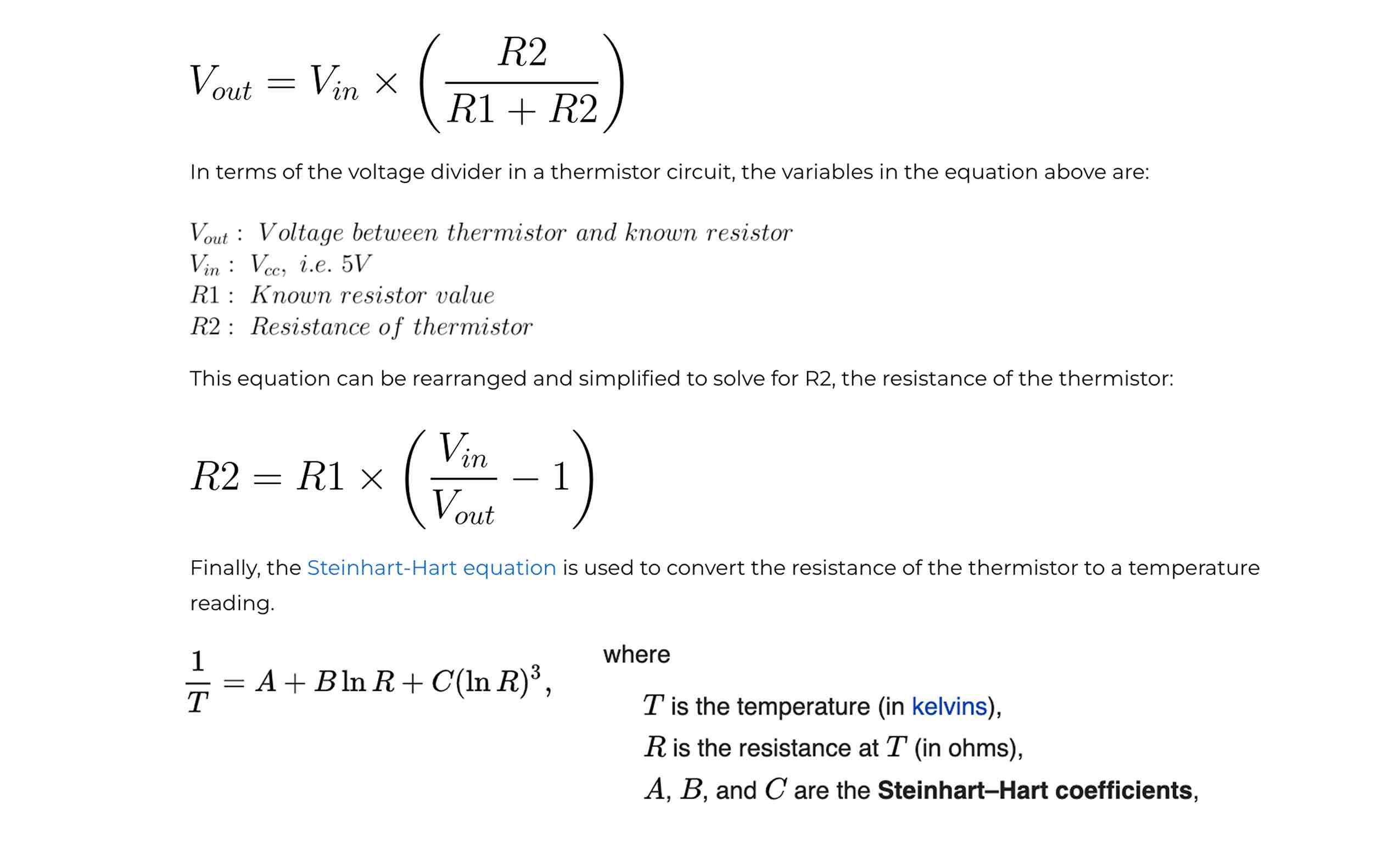
I searched for code posted online that creates the conversion from the voltage divider value into temperature in arduino IDE. The last resource Elegoo tutorial worked best for me but since they are using liquid crystal screen to present the values I took that part out. Also changed the max value here: double tempK = log(10000.0 * ((4095.0 / tempReading - 1))); to 4095 from 1023 because I am working with a feather board not arduino and it can work with higher values.
Thermister Code
Basic Thermister Serial Plotter
int tempPin = A0;
//                BS  E  D4 D5  D6 D7

void setup()
{
Serial.begin(9600);
}
void loop()
{
  int tempReading = analogRead(tempPin);
  // This is OK
  double tempK = log(10000.0 * ((4095.0 / tempReading - 1)));
  tempK = 1 / (0.001129148 + (0.000234125 + (0.0000000876741 * tempK * tempK )) * tempK );       //  Temp Kelvin
  float tempC = tempK - 273.15;            // Convert Kelvin to Celcius
  float tempF = (tempC * 9.0)/ 5.0 + 32.0; // Convert Celcius to Fahrenheit
  /*  replaced
    float tempVolts = tempReading * 5.0 / 1024.0;
    float tempC = (tempVolts - 0.5) * 10.0;
    float tempF = tempC * 9.0 / 5.0 + 32.0;
  */

  //Serial.print("Temperature: ");
  Serial.println(tempF);
  //Serial.print(" F; ");
  //Serial.print(tempC);
  //Serial.println(" C");


  delay(500);
}
int tempPin = A0;
//                BS  E  D4 D5  D6 D7

void setup()
{
Serial.begin(9600);
}
void loop()
{
  int tempReading = analogRead(tempPin);
  // This is OK
  double tempK = log(10000.0 * ((4095.0 / tempReading - 1)));
  tempK = 1 / (0.001129148 + (0.000234125 + (0.0000000876741 * tempK * tempK )) * tempK );       //  Temp Kelvin
  float tempC = tempK - 273.15;            // Convert Kelvin to Celcius
  float tempF = (tempC * 9.0)/ 5.0 + 32.0; // Convert Celcius to Fahrenheit
  /*  replaced
    float tempVolts = tempReading * 5.0 / 1024.0;
    float tempC = (tempVolts - 0.5) * 10.0;
    float tempF = tempC * 9.0 / 5.0 + 32.0;
  */

  Serial.print("Temperature: ");
  Serial.print(tempF);
  Serial.print(" F; ");
  Serial.print(tempC);
  Serial.println(" C");


  delay(500);
}
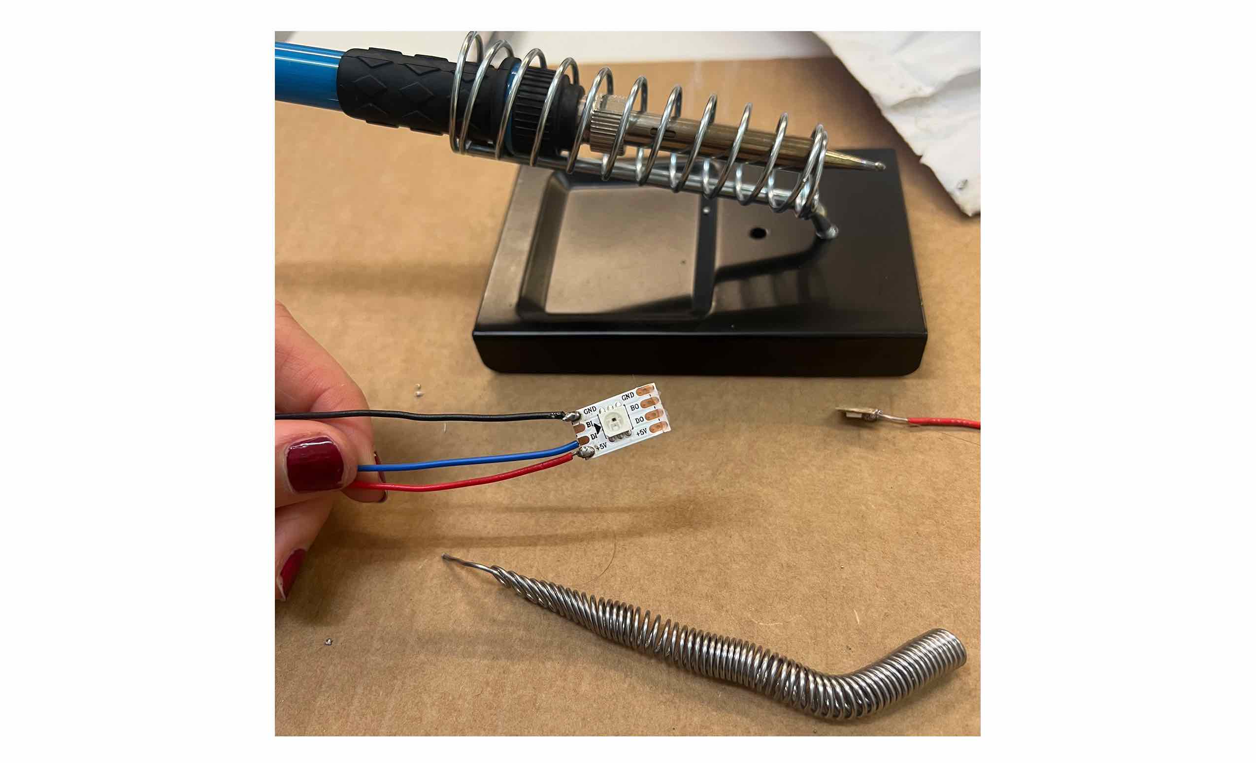
Soldering Neopixels and Ciruit
Soldering Tips:
I connected a postive wire, a ground wire and a wire for the pin on the copper tabs on a single neopixel.
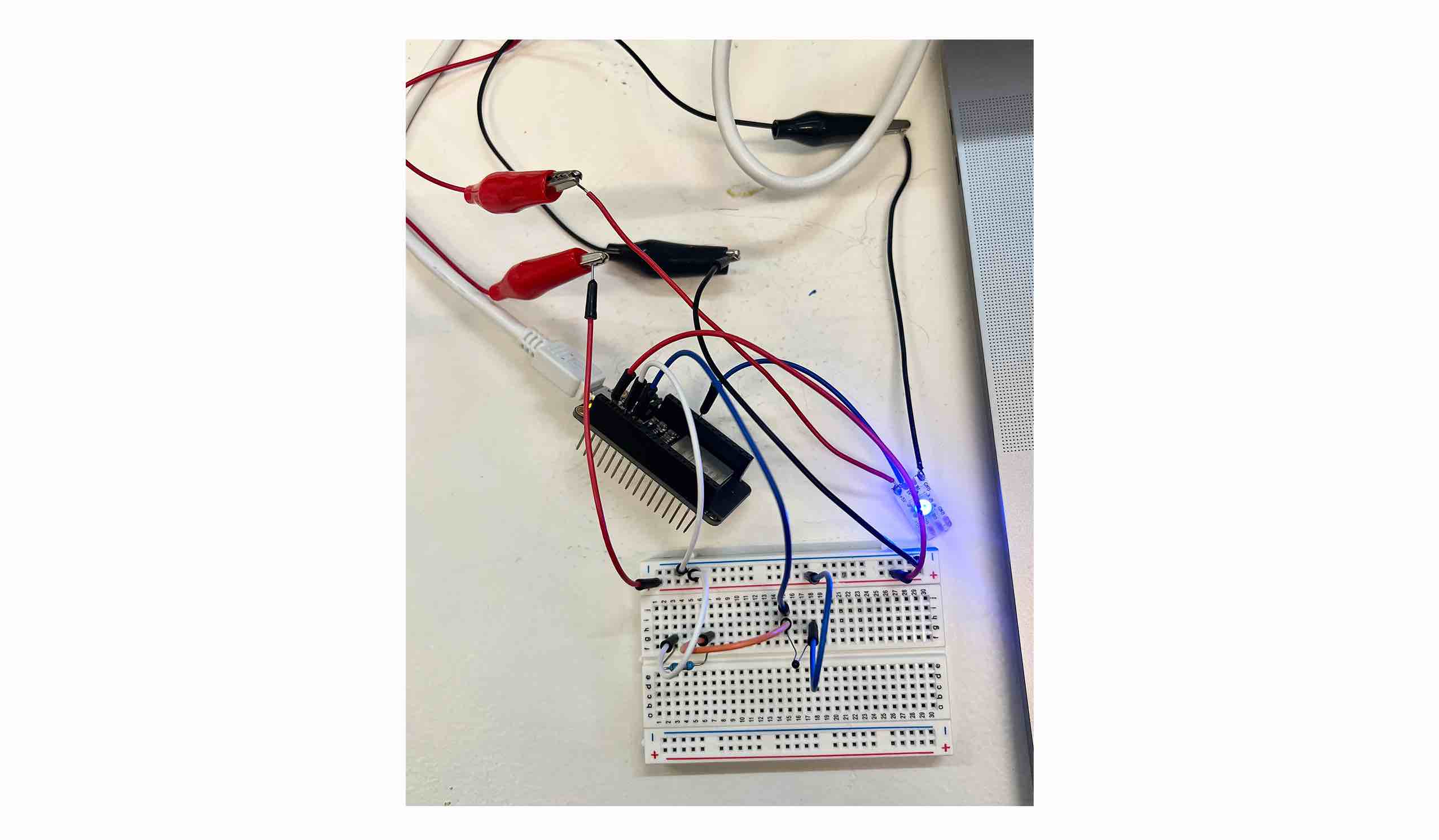
Joint Test
Joint Code
#include <Adafruit_NeoPixel.h>
#ifdef __AVR__
 #include <avr/power.h> // Required for 16 MHz Adafruit Trinket
#endif

#define PIN 12

#define NUMPIXELS 1

Adafruit_NeoPixel pixels(NUMPIXELS, PIN, NEO_GRB + NEO_KHZ800);

#define DELAYVAL 500

void setup() {

#if defined(__AVR_ATtiny85__) && (F_CPU == 16000000)
  clock_prescale_set(clock_div_1);
#endif
  // END of Trinket-specific code.

  pixels.begin(); // INITIALIZE NeoPixel strip object (REQUIRED)
}

void loop() {
  pixels.clear(); // Set all pixel colors to 'off'

    pixels.setPixelColor(i, pixels.Color(0, 0, 150)); // moderate blue

    pixels.setPixelColor(i, pixels.Color(255, 0, 0)); // bright red

    pixels.show();   // Send the updated pixel colors to the hardware.

    delay(DELAYVAL); // Pause before next pass through loop
  }
}
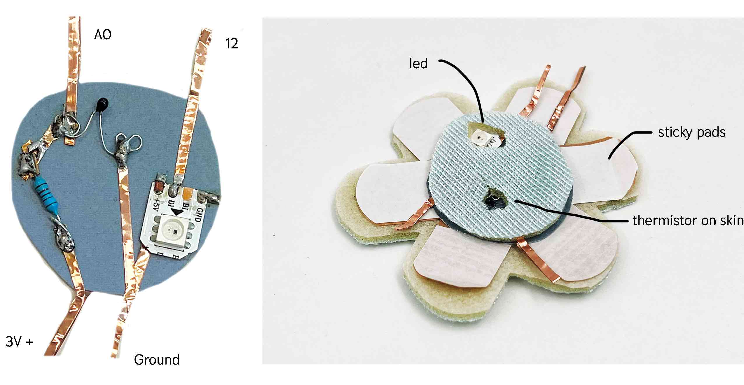
Embedding in a soft circuit patch
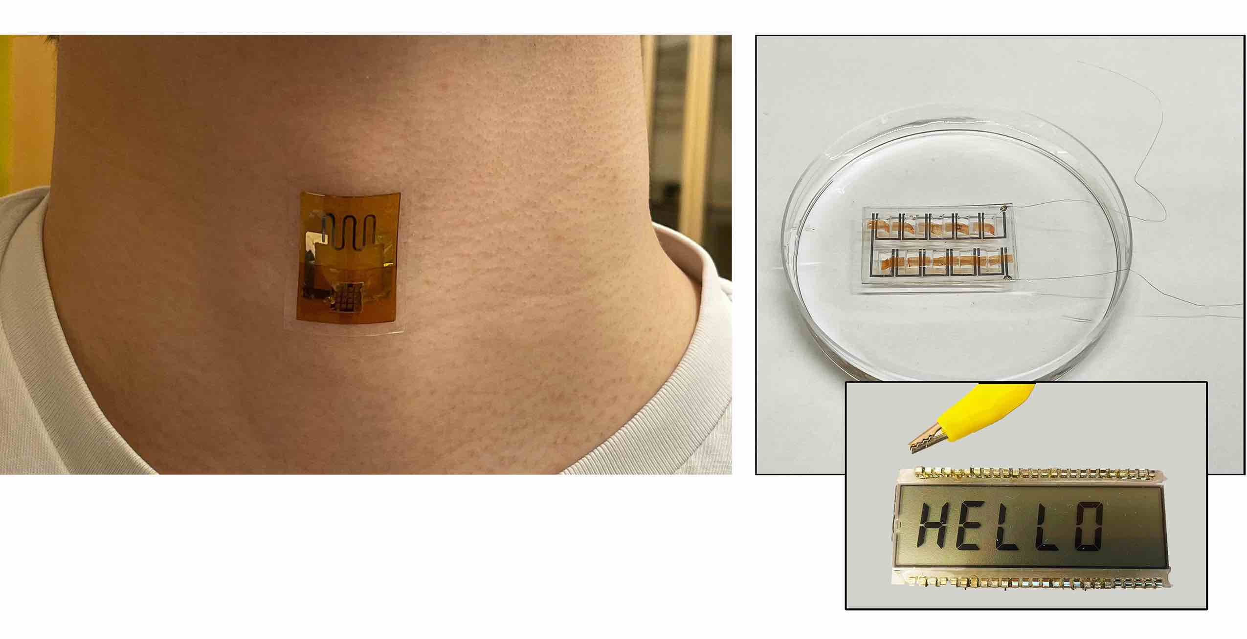
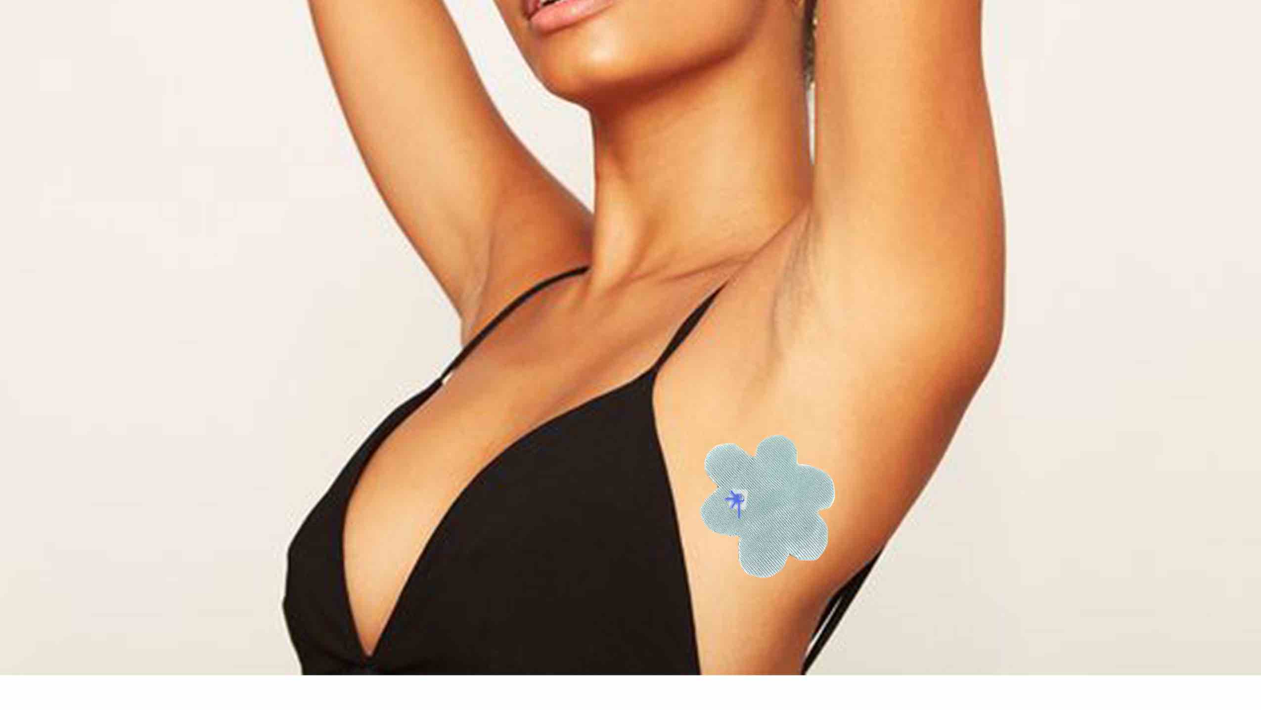
For the design I am making a soft patch. I was thinking about how Starface acne patches and bandaids are like an accessory for young people and was hoping to make my thermometer similar. I decided to cut it in a flower shape to make it cute. The soft curcuit uses conductive copper tape and holds the resistor, thermister and neopixel LED. There are 4 wires coming out from the patch which ideally would not be there but this is a prototype.
 I soldered the circuit on a piece of paper using conductive copper tape. I made a soft and sticky flower using a cushy piece of scrap fabric and bandaids. After making and testing I realized a big mistake I put the led on the wrong side :( it is facing the skin instead of the outside. Since I am rushed on time and this is still a very messy prototype i did not fix it. I am happy I have a simple physical product that could be expanded on.
Reflection
I am finally feeling more comfortable with electronics after this third week. I felt such pride after setting up the joint circuit and doing a few other steps without help and seeing that they worked! I wish that I could make a better second prototype with the correct LED direction, a switch and code that could "store" the data until the switch is pressed and the LED would be triggered. At the end it is good to get a bit more experience with temperature tools because these may be necessary for my final project - working with heated scaffolds for silkworms.
What an amazing journey! I am grateful for all I have learned in these first 3 months and the support, inspiration and collaboration along the way.