13. Skin Electronics

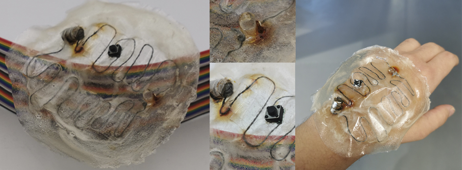
Making simple circuits on bioplastic
I tryed integrate the circuit on the bioplatic, I used first celotape to sticked in place but I discovery that the places exposes to the bioplastic are being eating by the bioplastic and get oxidation in less than a 10 mintutes and in the places where are insulated by the tape worked perfectly so in the future I will use the tape to insulate and then pour the bioplastic to get a better attach to the skin
I have tried to progressively test a simple circuit, one LED, two LEDs, three LEDs, a blink, a button, a sensor like this in an exponential way until I have achieved what I wanted to do.
Preparing Arduino UNO
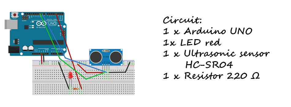
The first thing I tried was to recreate with the arduino the circuit that I made in wearables.
But this time I used a single led and an ultrasonic sensor, which I programmed with the Arduino UNO
*/

int TRIG = 10;          // trigger en pin 10
int ECO = 9;            // echo en pin 9
int LED = 3;            // LED en pin 3
int DURACION;
int DISTANCIA;

void setup()
{
  pinMode(TRIG, OUTPUT);    // trigger como salida
  pinMode(ECO, INPUT);      // echo como entrada
  pinMode(LED, OUTPUT);     // LED como salida
  Serial.begin(9600);       // inicializacion de comunicacion serial a 9600 bps

}

void loop()
{

  digitalWrite(TRIG, HIGH);         // generacion del pulso a enviar
  delay(1);             // al pin conectado al trigger
  digitalWrite(TRIG, LOW);      // del sensor

  DURACION = pulseIn(ECO, HIGH);    // con funcion pulseIn se espera un pulso
                    // alto en Echo
  DISTANCIA = DURACION / 58.2;      // distancia medida en centimetros
  Serial.println(DISTANCIA);        // envio de valor de distancia por monitor serial
  delay(200);               // demora entre datos


}
Uploading the code to Attiny
I tried uploading the code to the Attiny with the Arduino UNO but it gave me an error when uploading it.
So I tried with the programer

Making a simple blink with the Attiny
/*
  Blink

  Turns an LED on for one second, then off for one second, repeatedly.

  Most Arduinos have an on-board LED you can control. On the UNO, MEGA and ZERO
  it is attached to digital pin 13, on MKR1000 on pin 6. LED_BUILTIN is set to
  the correct LED pin independent of which board is used.
  If you want to know what pin the on-board LED is connected to on your Arduino
  model, check the Technical Specs of your board at:
  https://www.arduino.cc/en/Main/Products

  modified 8 May 2014
  by Scott Fitzgerald
  modified 2 Sep 2016
  by Arturo Guadalupi
  modified 8 Sep 2016
  by Colby Newman

  This example code is in the public domain.

  https://www.arduino.cc/en/Tutorial/BuiltInExamples/Blink
*/

// the setup function runs once when you press reset or power the board
void setup() {
  // initialize digital pin LED_BUILTIN as an output.
  pinMode(LED_BUILTIN, OUTPUT);
}

// the loop function runs over and over again forever
void loop() {
  digitalWrite(LED_BUILTIN, HIGH);   // turn the LED on (HIGH is the voltage level)
  delay(1000);                       // wait for a second
  digitalWrite(LED_BUILTIN, LOW);    // turn the LED off by making the voltage LOW
  delay(1000);                       // wait for a second
}
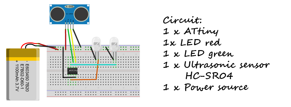
Attiny with Ultrasonic sensor
After uploading the code with the ATtiny I integrated it into the circuit but I continued using the programmer as it gave me a stable source of electricity
#define Green 5
#define Yellow 3
#define Red 2
#define buzzer 4


const int trigPin = 1;
const int echoPin = 0;
long duration;
int distance;


void setup() {
pinMode(trigPin, OUTPUT); // Sets the trigPin as an Output
pinMode(echoPin, INPUT);  // Sets the echoPin as an Input
pinMode(Green, OUTPUT);
pinMode(Yellow, OUTPUT);
pinMode(Red, OUTPUT);
pinMode(buzzer, OUTPUT);
}
void loop() {
// Clears the trigPin
digitalWrite(trigPin, LOW);
delayMicroseconds(2);
// Sets the trigPin on HIGH state for 10 micro seconds
digitalWrite(trigPin, HIGH);
delayMicroseconds(10);
digitalWrite(trigPin, LOW);
// Reads the echoPin, returns the sound wave travel time in microseconds
duration = pulseIn(echoPin, HIGH);
// Calculating the distance
distance= duration*0.034/2;
  if(distance > 200) {
    digitalWrite(Green, HIGH);
    digitalWrite(buzzer, LOW);
    digitalWrite(Yellow, LOW);
    digitalWrite(Red, LOW);
  }
  if(distance <= 200 && distance >100) {
    digitalWrite(Green, LOW);
    digitalWrite(buzzer, LOW);
    digitalWrite(Yellow, HIGH);
    digitalWrite(Red, LOW);
  }
  if(distance < 100) {
    digitalWrite(Green, LOW);
    digitalWrite(buzzer, HIGH);
    digitalWrite(Yellow, LOW);
    digitalWrite(Red, HIGH);
    //tone(buzzer, 100, 100);

  }
}
Adding the Attiny to the project
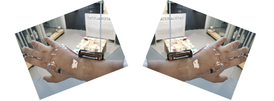
When I started to test it with an external source of electricity, it was a bit complicated since the connections moved and the circuit opened, which made me nervous and I thought it was the code, the elements or things like that but they were things more Simple such as that the sensor is very heavy and when it fell it moved the LEDs or that some cable was released. I recommend that you review the basics above and then move forward.
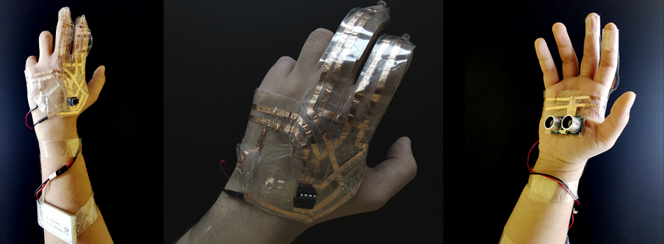
The Skin Electronic
The led lights show a little our feeling with the pandemic and our fear of the approach, the green Led, which is located on the index finger, will always be on and the moment someone approaches the middle finger the red light will turn on that will indicate to us that it has entered my personal perimeter and the way to integrate it in that finger is also to give it a little grace since it would be to show the index finger to the person who is too close.
Making circuit with the BreadBoard