05. E textiles
HOW ARE WE BEING CONNECTED?

Technology applied to textiles is being used as an another interaction with our bodies. We can see it in the fashion industry as a way of expressing emotions, health care, security, art… but my favorite are the ones that use it as a way of understating how our bodies work, such as receiving data from our movements, health interior and act in consequence of that information.
CONDUCTIVE WEEK
During this week we learnt how to apply electricity to textiles. We were given some tutorials about basic technology and Arduino that for me were a reminder as I learnt it at my degree.
Working with technology can be mind blowing. It is another language that you need to learn and you need to practice it… a lot. And if you’re still struggling with it, there are a lot of tutorials and open code that can help you designing your circuit and programming it. Here are some of the best platforms to look for help ( or maybe just inspiration!): Arduino Forum where you can find really useful tips about how to use the code and wich tools do you have; and if you want to give your programming a much more artistic look, you can interact in the digital world by making digital art with your phisical sensor. In this page you can find some inspiration and its embebed codes that you can modify (it is one of my favorite open source platforms)Generative Gestaltung.
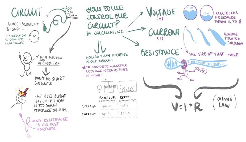
Here's my little mind map to understand the basics:
Nevertheless, working with soft materiales makes all the interaction different. I was really impressed in how we could create different sensors but using conductive fabrics. I’ve never had the chance to experiment with them as in Product Design they feel like everything must be hard.
At the beginning I didn’t know what to do as there are a lot of examples and I didn’t know which one select. Finally I made up my mind in doing a capacity sensor and a button. I was inspired by the examples of kobakant Capacity sensor and Fabric button .
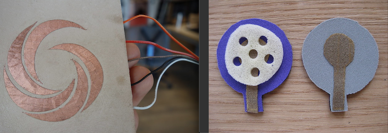
But first of all I needed to be more hands on, and test with the conductive fabrics and get some knowledge on how they work. I fabricated a basic digital sensor to test the interaction and connection, a button. Later on I moved to my analog sensor.
DIGITAL but also ANALOG SENSOR
I was moved to experiment with a different kind of actuator as I wanted to do something different and more “cool”. So I decided to use a piezoelectric to make sound. It known as a sensor but it can also modify the environment (actuator) and create sounds (not the most pleasant ones but…). However we didn't have this piece at the center so I decided that I would exeriment first with a LED and transfer the Arduino Code after knowing that the soft sensor works.
I didn't end up doing the capacity sensor as we didn’t fully understand how does the example work. The information wasn't clear enough for me, it is a difficult one. Being inspired by that example, I designed a sensor by creating resistance with Velostat.
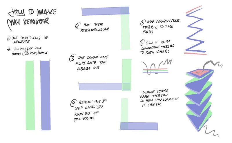
I remember making this “origami” acordeones when I was a child and I trasladarlo to the sensor. This will work as a analog sensor as it creates a difference in resistance that interferes in the energy current. So when it’s in it’s ALARGADO the electricity moves better: there is low resistance. But when it’s pressed, the layers increase it, making difficult to electricity to move thought it.
I tested the connection with a led and the connections worked! So I designed the final circuit that could be applied on the fabric. Before sewing everything I made sure that all the connections worked.
One of the many advantages of sewing with the conductive yarn instead of soldar is that you can go back.
Tools:
- Conductive yarn
- Velostat: 2 long pieces
- LED
- 3V batterie
- Conductive fabric
- Needle
This was the code used to read the analog value from the sensor and connecting it to the LED:
int sensorPin = A0;    // select the input pin for the potentiometer
int ledPin = 10; // select the pin for the LED
int sensorValue = 0;  // variable to store the value coming from the sensor
int newSensorValue;

void setup() {
// declare the ledPin as an OUTPUT:
pinMode(ledPin, OUTPUT);
pinMode(sensorPin, INPUT);
Serial.begin(9600);
}

void loop() {
// read the value from the sensor:
sensorValue = analogRead(sensorPin);

//map the values to something usable
//map(value, fromLow, fromHigh, toLow, toHigh)
newSensorValue = map(sensorValue, 0, 1023, 0, 100);

Serial.print("newSensorValue = ");
Serial.println(newSensorValue);
}
As an analog sensor, its value can be modified acording to the resistance and voltage, from 0 to 1023. I created the same sensor away from the fabric so I could connect it to Arduino. The results were that the longer the sensor is, the higher the current; but if you press it, Velostat works as an insulator so there is much more resistance (so less intensity). First we did a circuit example with a simple batterie of 3V and we could see the brightness difference in the LED. However when we wanted to connect it to Arduino and control the value throught the pressure and bright intensity, it didn't work. It was or ON or OFF.
So...I did another truly analog sensor!
ANALOG SENSOR
I didn't want to complicate my mind too much as there wansn't enough time. So I created one that I knew it was going to work: Neoprene Bend Sensor with Velostat from Kobakant.
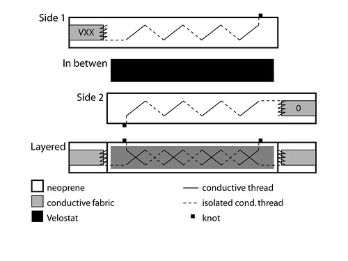
I wanted to modified it a little bit so it could look like the first sensor:
I insert some wool in it so it had more fluffly appearance, but in order for it to be less insulator I sewed some conductive yarn from the face in touch. This way it could be in touch with the Velostat.
Tools:
- 2 pieces of fabric cut as wanted
- Conductive yarn
- Velostat: 1 long piece in the same shape as the fabric
- LED
- 220 Ohms resistance
- Conductive fabric
- Arduino
- Cocrodiles
- Jumpers
- Needle
First it was tested in a simple circuit with a 3V batterie. It works!! The different volumes of the sensor will interact differently on the intensity of the LED.
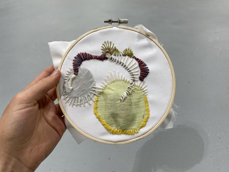
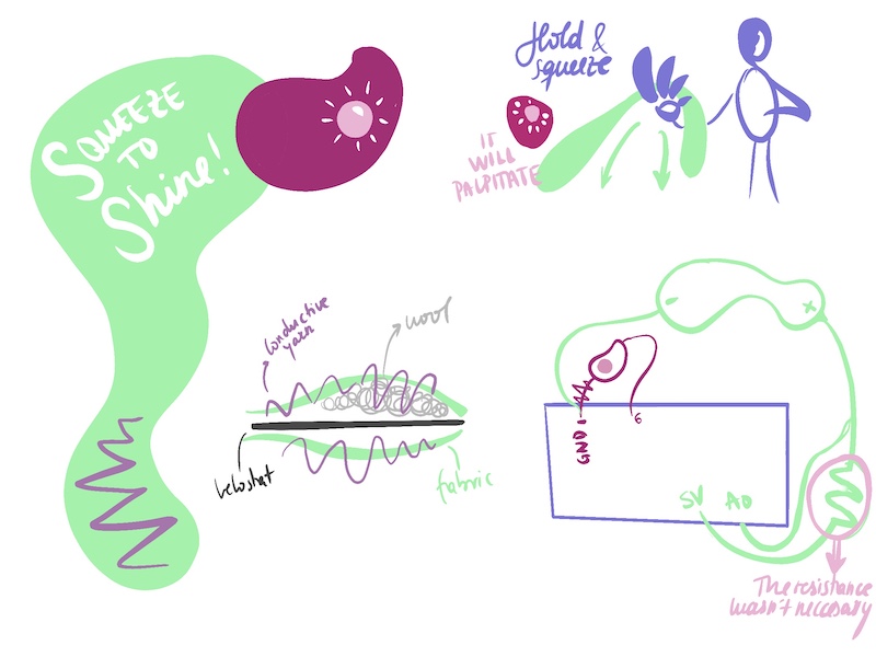
Then when we were going to connect it to Arduino, something was wrong. I followed the skecth from the tutorial and there was a a 10K resistance and we fgured that it was too much and didn't allow the sensor to work. Arduino couldn't read the range until I took off the resistance and...THE LED STARTED TO BLINK ACCORDING TO THE SENSOR!! YAY! And apparently I created a baby an anemone that likes to be hold (it makes a variation when you take it).
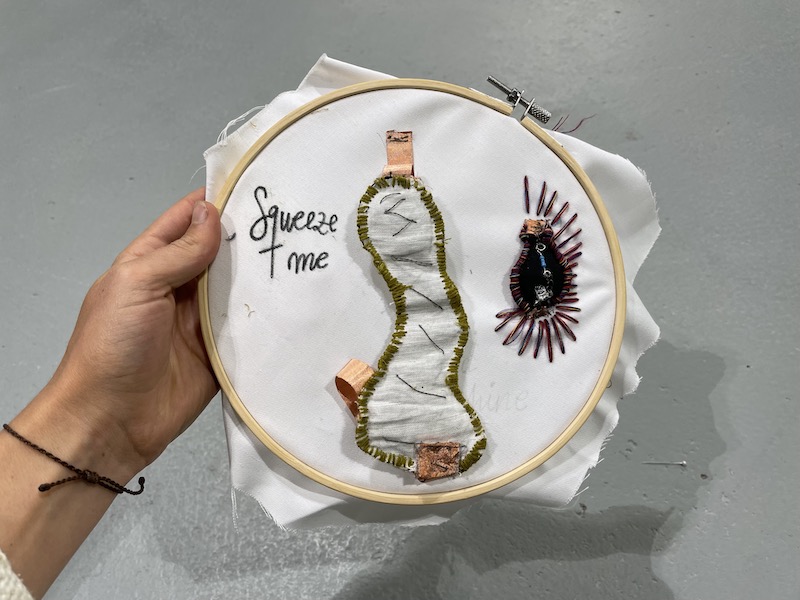
So after reading the the value and mapping it so it could be in the same range of the LED (from 600-1023 to 0-255); I started sewing everything in order to put it in the same fabric.
This was the code (again) to associate the value of the sensor to the intesisty of the LED:
int sensorPin = A0;    // select the input pin for the potentiometer
int ledPin = 9;     // select the pin for the LED
int sensorValue = 0;  // variable to store the value coming from the sensor
int newSensorValue;

void setup() {
// declare the ledPin as an OUTPUT:
pinMode(ledPin, OUTPUT);
pinMode(sensorPin, INPUT);
Serial.begin(9600);
}

void loop() {
// read the value from the sensor:
sensorValue = analogRead(sensorPin);

//map the values to something usable
//map(value, fromLow, fromHigh, toLow, toHigh)
newSensorValue = map(sensorValue, 900, 1023, 0, 255);

//write the new value to the LED
analogWrite(ledPin, newSensorValue);

//print the new value to the serial monitor
Serial.print("newSensorValue = ");
Serial.println(newSensorValue);

}
Here's the video of the whole process for the analog sensor: