10. From fibers to fabrics
GETTING DIZZY
INSPIRATION
brief begrounded from Lara Campos on Vimeo.
URSULA, Spinning Machine 4.0
As a first year node we decided to build the Hilo’s spinning machine 2.0. We thought that it was a good assignment for the team and we should develop some other tools.
The day after the lecture we were given the pieces cut. As a team we decided to build the first machine together and see how it works, because we all needed to analyze all the steps. Building the machine was frustrating for the team, as we had several pieces (for more than one machine) and each for a different version. So everything was mixed and we took longer because of this.
THis was the list of the components that we were given (sorry it is in Spanish):
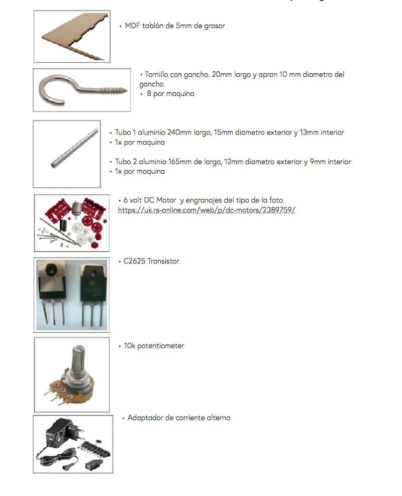
We tested the electronics apart from the structure to understand how the elastic band works and how much resistance can it make.
In the first photo we can see Hilo's Spinning Machine 2.0
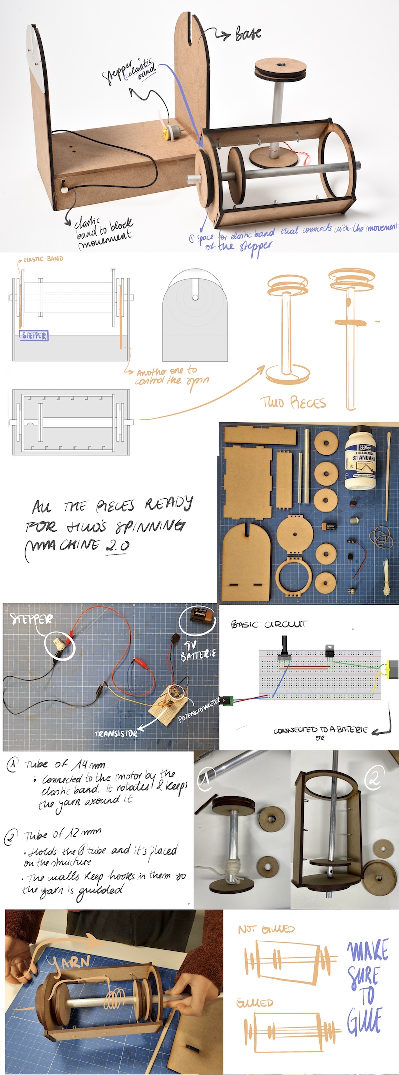
Electronics and machine working:
BRAINSTORMING
After (finally) getting Hilo’s machine assembled, we decided to do a brainstorming in order to put in common the ideas of our new version of the spinning machine. We divided this brainstorming by 4 fields: design of the product, user experience, electronics and other tools or machines that could be linked. We took about 10 minutes of thinking out loud improvements.
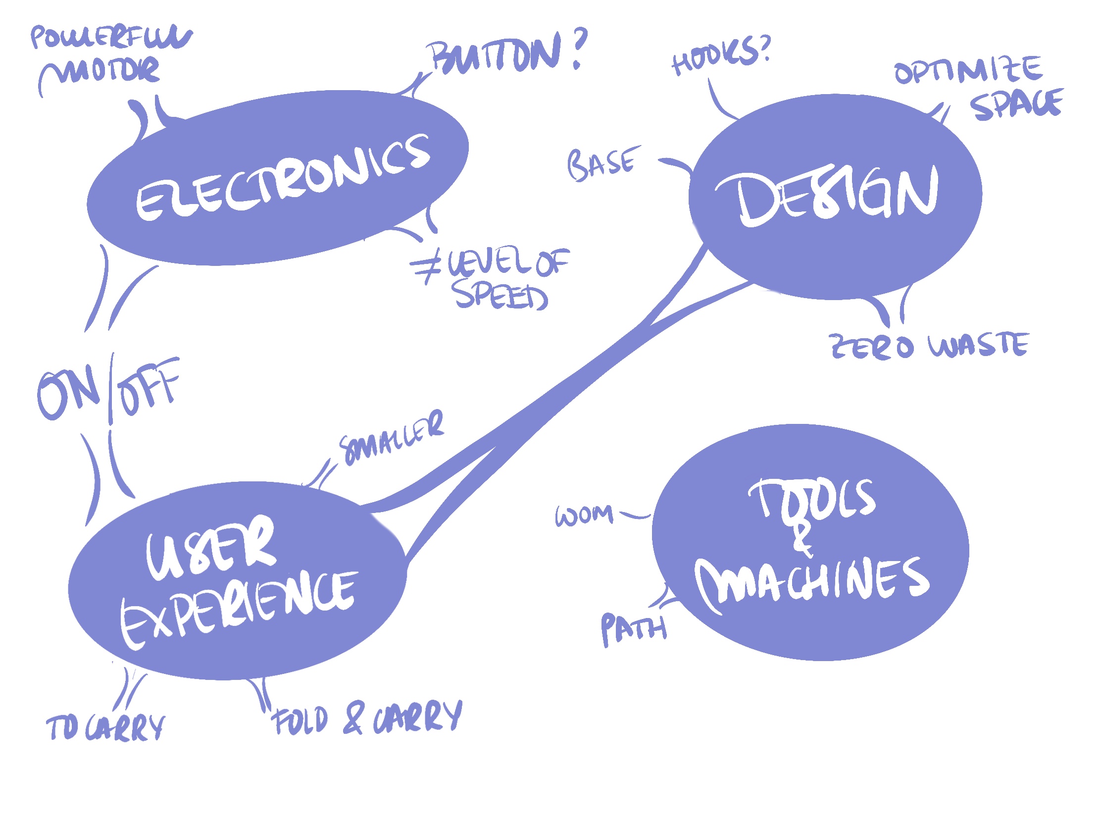
Based on our stressful situation on building it up, there were a lot of ideas in the user experience field and design. After gathering about 15 ideas, we selected 5 of them so it could be an approachable project. In the electronics we decided that there was a need to turn the circuit on easier, and not connect it to the battery directly.
At the User Experience we decided to try to make it as a transportable machine, easy to carry; and a little smaller. For the design improvement, we saw the necessity of reducing the waste and the material used, as there we analized that there were several components that weren’t that important in size. However more changes were included during the design process as we saw the opportunity. For example we included a mini loom in the base of the machine and a user manual (how to build it after cutting and how to use it) to make the Open Source file more complete.
After defining which path we were going to take as a group, we divided the work by teams: Edu for electronics, Marisa and Olatz for documentation and creating a manual; and Arantza and Elsa for the design of the new machine. As a group work, every task was linked to the others so communication was crucial to make it work.
DESIGN with Rhinoceros
After deciding what improvements we would make, it was time to design. We used Catherine Euale’s files to use the same measurements and make sure it would work. From that point, we made changes.
BASE
We wanted one of the sides to be able to be opened up to see the inside of the machine. We used Boxes.py website which generates the box that you want.
It has different shapes and types of box options. The plans it generates are for laser cutting because it has tabs that are used to fit the pieces.
One of the corners had to be “flexible” to open and close the machine. So, once you have entered the parameters, the box is generated with a parametric design to obtain that freedom of movement and you only have to download the file
We made some changes to that file. The box had 2 curved corners, but we wanted one. We combined it with the original file and got the plans of the box we wanted. Moreover, we reduced the height of the base, in order to save material (instead of 6 cm of height, it had 3 cm).
GEAR
We put the gears on the surface of the structure to have more space for other components. They had a circular shape, which complicated their distribution so as not to generate material waste and without affecting the structure of the machine.
As a result, we put 3 of them on each side of the structure and the other one inside the circle that would serve as the lathe structure. There will be waste of material, however we used it as another tool (you will see it).
Moreover, we scaled the diameter of 4 of them, because we noticed that they were just a stopper. The other ones were more “important”, I mean, they were connected to the motor with a rubber band, so if you change the diameter, it will affect the speed. We decided to leave as the original one, just in case.
We maintain the diameter of the holes that are in the gear. We used the same tubes as in the Speed machine 3.0.
ELECTRONICS
We received a sketch of a circuit with a DC motor connected to a transistor and a potentiometer. This circuit was supplied by a 9-volt battery. We did not have a clear or precise image of what type of transistor or if they have orientation, but like everything with trial and error we could discover it.
After closing the circuit and assembling the machine, we could analize the workflow of the machine. In the updated machine we removed the battery by electrical current using a transformer that we placed at 9 volts. Other changes were to added as an on/off button. However we didn't put it at the final circuit because we didn't see the neccesity. The rest of the circuit stayed the same since it worked perfectly for what we needed.
This is the graphic of the final circuit:
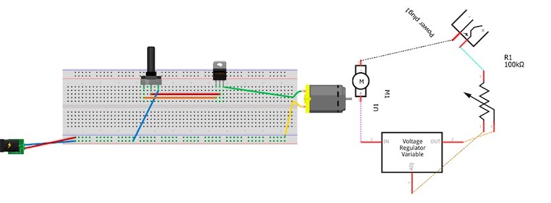
After approving the changes, we got down to work and replaced the elements in the breadboard. We decidede to keep it in there and not soldering because we just had one transistor and if something breaks in it is easy to fix.
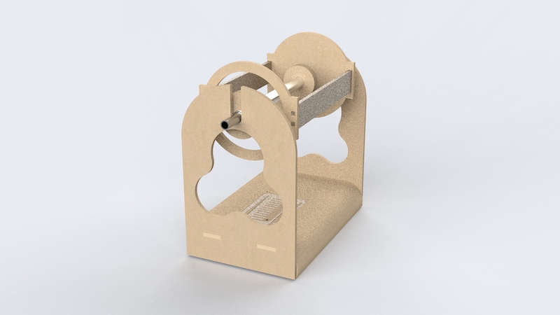
STRUCTURE OF THE LATHE
We started placing the pieces to optimise the space. We started to place the pieces in order to optimise the space. We saw that the long pieces of the lathe could fit between the pieces of the structure if we reduced their width.
So we reduced it because it didn't affect the operation and it was to our advantage to do so. Instead of having 3 tabs, it would have 2 because they would be too thin and they could break easily.
HOLES
We added some holes to be able to regulate the speed with the potentiometer and another one to pass the power supply cable through.
URSULA
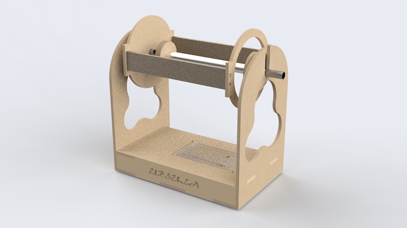
REDUCING WASTE AND MATERIAL
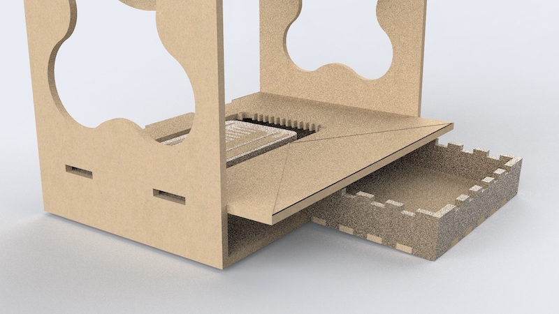
This was the distribution to save material. It is true that we managed to save a little bit, however, we made a 2x1 machine: an hilo spinning machine and a mini loom, plus we added a small box to store tools.
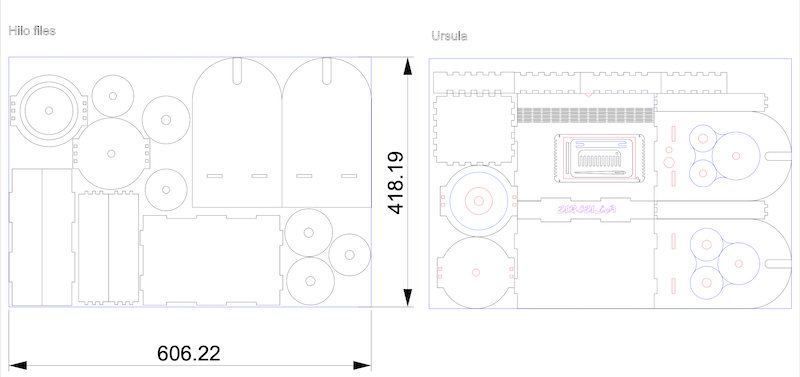
LASER CUTTING
For laser cutting the file was very important to be clear and organized with the layers and colors. As we optimized the space in the material, a lot of components needed to be cut before the perimeter. This is as simple as divide them in many layers.
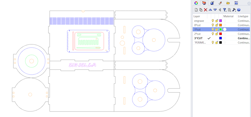
We used a MDF of 5 mm. The parameters for the laser cut were:
For cutting:
- Min power: 70
- Max power: 75
- Speed: 25
For engraving:
- Min power: 35
- Max power: 35
- Speed: 400
SPINNING
OTHER TEAM TOOLS
-Edu’s hook and circular loom - Marisa’s loom
Manual
We saw the necessity, based in our experience, of making a user manual. This little book includes how to build the machine, step by step; the electronics circuit and where it is placed; and a little explanation on how the spinning machine works and how to use the yarn created in the loom.
Dowloadable files
Here you can find the downloadable files for Ursula. There are many files where you can edit the measures in order to cut it, see the 3D in Rhino
Useful links
Lara Campos assigment Lara Campos project reGrounded Living spinning machine