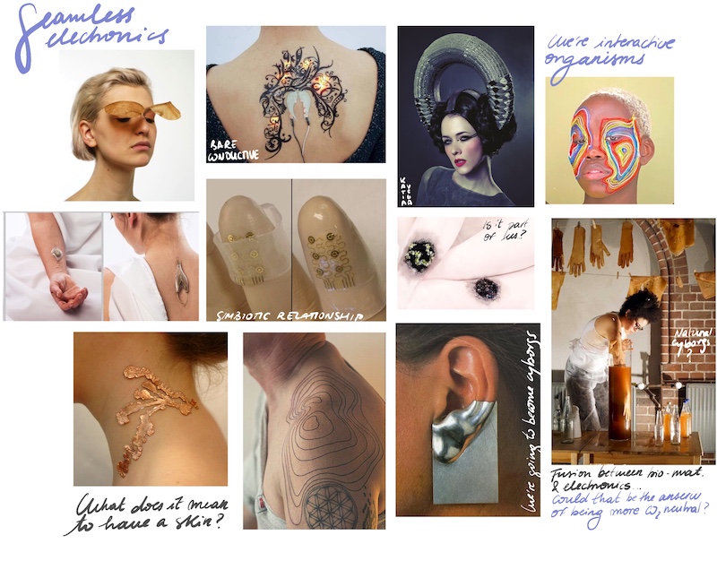
13. Skin electronics
WHAT DOES IT MEAN TO HAVE A SKIN?
Arantza and I decided to work together for this week as we were a little lost with how many incredible things we could do (of course); but also, because we wanted to conmemorate the last week. It was our last chance to do something together.
ONE IS THE CYBORG

Arantza has the initial idea of bringing hugs to another level. As we all know, we can distinguish different hugs that depending on how you’re attached to the other person; or what you want to express. She wanted to integrate this hugs as our actuator of the circuit, that would have been read by capacitive sensors placed on the body. Depending on the hug (so a different part of the body is touched) a different color will bright.
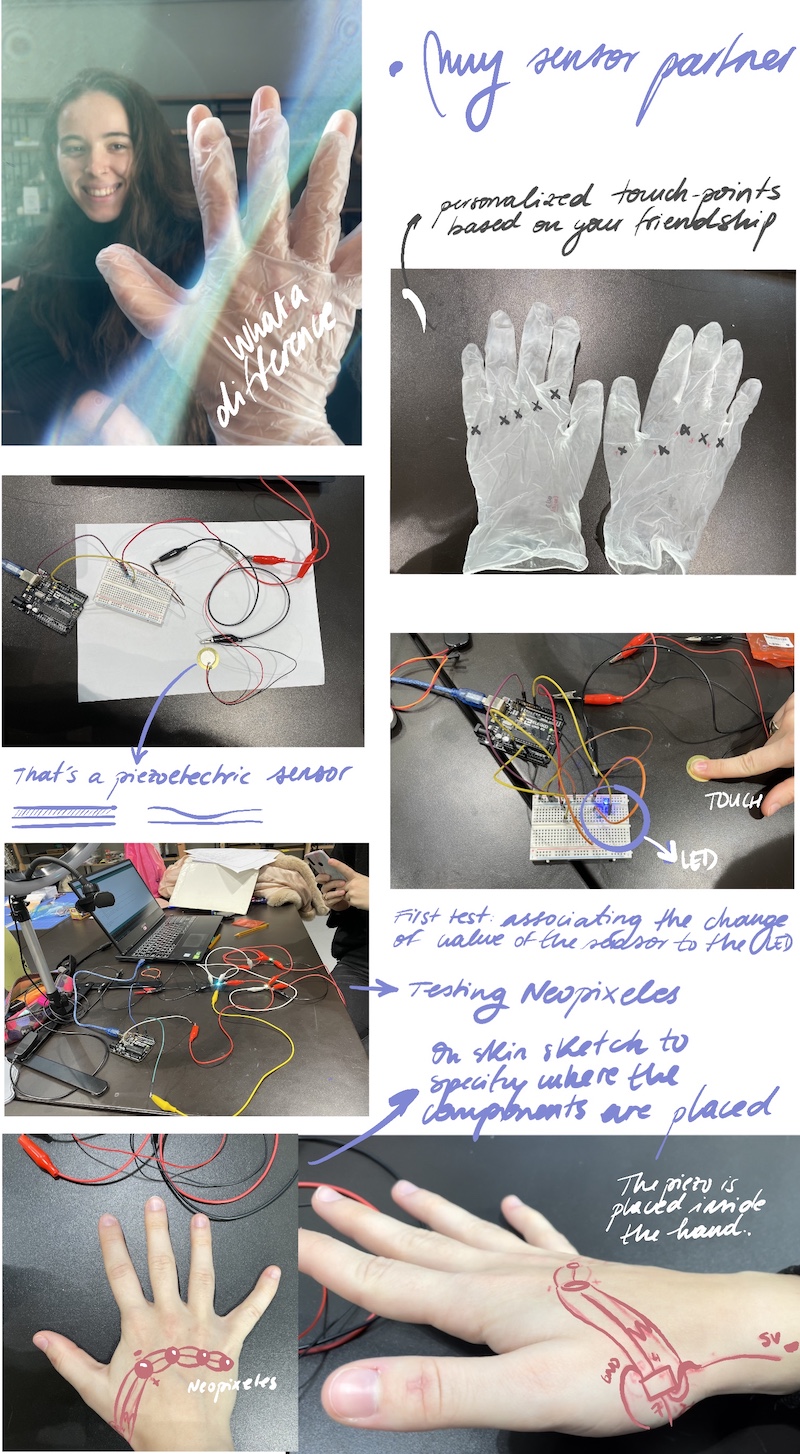
However, this idea apart from awesome, was a bit difficult for us to accomplish as it would be very big and the complexities of the resistances, components and connections would have increased exponentially. That’s why we decided to focus on the hands in order to make it simpler and as a sign of our friendship as we are regularly holding hands :)

After changing the area of work we thought about making an instrument with our hands. One would be the instrument and the other one, the player. To create the sound we started with a piezoelectric sensor, but as an actuator (its vibration generates sound). We programmed it with Arduino with just random noises, but the sound wasn’t very loud, so we decided to use it as a sensor. This decision was accurate because we were also working with external pressure. The updated actuator would be a neopixel: the more the pressure the more the light. We used a neopixel instead of a LED in order to improve from other weeks as we didn’t have the chance to test it yet.
WORKFLOW IN TESTING ELECTRONICS SEPARETLY
Here is a little video of the different steps
Skin electronics.mp4 from elsa tfg on Vimeo.
CODES THAT WERE USED DURING THE PROCESS
-
Read the piezoelectric sensor and map the value
int analog_sensor_pin = A0; //change the pin, where the sensor is connected? int analog_sensor_value = 0; void setup() { pinMode(analog_sensor_pin, INPUT); Serial.begin(9600); } void loop() { analog_sensor_value = analogRead(analog_sensor_pin); //read the Voltage of the pin sensor Serial.println(analog_sensor_value); // print the value on the Serial monitor delay(100); } -
Associate the range read to a LED (we first try with this because it was easier to test the interaction)
int sensorPin = A0; // select the input pin for the potentiometer int ledPin = 10; // select the pin for the LED int sensorValue = 0; // variable to store the value coming from the sensor int newSensorValue; void setup() { // declare the ledPin as an OUTPUT: pinMode(ledPin, OUTPUT); pinMode(sensorPin, INPUT); Serial.begin(9600); } void loop() { // read the value from the sensor: sensorValue = analogRead(sensorPin); //map the values to something usable //map(value, fromLow, fromHigh, toLow, toHigh) newSensorValue = map(sensorValue, 900, 1023, 0, 255); //write the new value to the LED analogWrite(ledPin, -newSensorValue); //print the new value to the serial monitor Serial.print("newSensorValue = "); Serial.println(newSensorValue); } -
Connect and program apart the neopixels: understand how they work, and add more.
        #include <Adafruit_NeoPixel.h>

        #define LED_PIN    10

        // How many NeoPixels are attached to the Arduino?
        #define LED_COUNT 2

        // Declare our NeoPixel strip object:
        Adafruit_NeoPixel strip(LED_COUNT, LED_PIN, NEO_GRB + NEO_KHZ800);

        uint32_t off = strip.Color(0, 0, 0);
        int num_rainbow = 15;

        void setup() {

        strip.begin();           // INITIALIZE NeoPixel strip object (REQUIRED)
        strip.show();            // Turn OFF all pixels ASAP
        strip.setBrightness(50); // Set BRIGHTNESS to about 1/5 (max = 255)
        }

        void loop() {

        rainbow(10);             // Flowing rainbow cycle along the whole strip

        //strip.fill(off, 0, 10);  // turn the strip off
        //strip.show();  //display the color
        //delay(1000);

        }

        // Rainbow cycle along whole strip. Pass delay time (in ms) between frames.
        void rainbow(int wait) {

        for(long firstPixelHue = 0; firstPixelHue < num_rainbow*65536; firstPixelHue += 256) {
        for(int i=0; i<strip.numPixels(); i++) { // For each pixel in strip...

        int pixelHue = firstPixelHue + (i * 65536L / strip.numPixels());

        strip.setPixelColor(i, strip.gamma32(strip.ColorHSV(pixelHue)));
        }
        strip.show(); // Update strip with new contents
        delay(wait);  // Pause for a moment
        }
        }
- Join analog sensor with neopixels (Emma's code, because we needed a lot of help)
            #include <Adafruit_NeoPixel.h>

            // constants won't change. They're used here to
            // set pin numbers:
            const int ledPin = 10;     // the number of the neopixel strip
            const int numLeds = 2;

            //Adafruit_NeoPixel pixels = Adafruit_NeoPixel(8, ledPin);
            Adafruit_NeoPixel strip = Adafruit_NeoPixel(numLeds, ledPin, NEO_GRB + NEO_KHZ800);

            float brightness = 0;
            uint32_t color;

            int sensorPin = A0;    // select the input pin for the potentiometer
            int sensorValue = 0;  // variable to store the value coming from the sensor

            void setup() {
            pinMode(sensorPin, INPUT);
            Serial.begin(9600);
            strip.begin();
            //strip.setBrightness(80); // 1/3 brightness

            }

            void loop() {
            brightness = 50;
            for(uint16_t j=0; j<256; j++) {

            //Serial.print(" ");
            //brightness = map(sensorValue, 0, 70, 255, 0);

            for(uint16_t i=0; i<strip.numPixels(); i++) {

            sensorValue = analogRead(sensorPin);
            Serial.println(sensorValue);
            brightness = map(sensorValue, 0, 70, 255, 50);
            brightness = constrain(brightness,0, 255);

            byte WheelPos = (i*1+j) & 255;

            if(WheelPos < 85){
                    color = strip.Color(brightness/255 * (WheelPos * 3), brightness/255 * (255 - WheelPos * 3), brightness/255 * (0));
            }
            else if(WheelPos < 170) {
                    WheelPos -= 85;
                    color = strip.Color(brightness/255 * (255 - WheelPos * 3), brightness/255 * 0, brightness/255 * (WheelPos * 3));
            }
            else {
                    WheelPos -= 170;
                    color = strip.Color(brightness/255 * 0, brightness/255 * (WheelPos * 3), brightness/255 * (255 - WheelPos * 3));
            }

            strip.setPixelColor(i, Wheel((i*1+j) & 255));

            }
            strip.show();
            delay(30);
            }

            }

            // Input a value 0 to 255 to get a color value.
            // The colours are a transition r - g - b - back to r.
            uint32_t Wheel(byte WheelPos) {
            if(WheelPos < 85) {
            return strip.Color(brightness/255 * (WheelPos * 3), brightness/255 * (255 - WheelPos * 3), brightness/255 * (0));
            }
            else if(WheelPos < 170) {
            WheelPos -= 85;
            return strip.Color(brightness/255 * (255 - WheelPos * 3), brightness/255 * 0, brightness/255 * (WheelPos * 3));
            }
            else {
            WheelPos -= 170;
            return strip.Color(brightness/255 * 0, brightness/255 * (WheelPos * 3), brightness/255 * (255 - WheelPos * 3));
            }
            }
ATTiny
We used an USBTinyISP to programm the microcontroller. It’s easier than doing it with Arduino: connect the ATtiny85 to the board and then the usb to the computer.
We followed this page and of course Emma's tutorial. The most important things are:
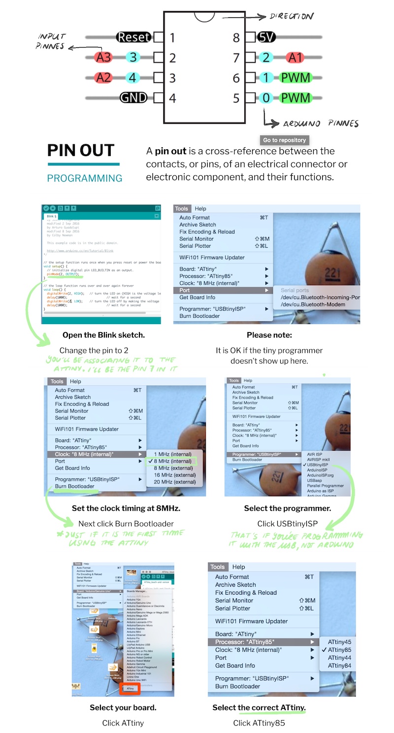
Make sure you select all parameters according to your component
Unfortunatly we had many troubles programing the code with Attiny because our USB didn't work with our computers. We tried though :(.
EMBROIDERING AN OLD CIRCUIT AS A SECOND SKIN
As we couldn't continue with our "cyborg friendship" project going, we decided to embed an Arantza's old circuit from Wearables week to a silicone layer. We had some leftover silicone discs from the jars from the soft robotics, and I took some of them and start sewing random things on. That's how we came with the idea of joining the two things together as the ATtiny from her circuit was already programmed. In her documentation you can find all the steps to programm this micro controller.
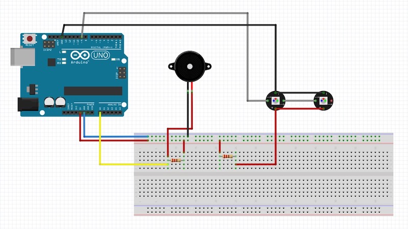
This is how the circuit was built in the breadboard:
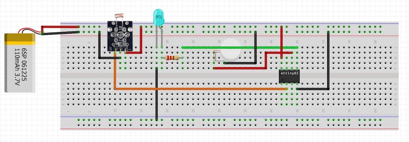
Transfering the circuit to an actual garment allowed us to include an interaction with the user. The idea was placing the LDR inside the palm of the hand, so when there is a need to activate the brething therapy (see more of the project in Arantza's wearable), you just need to close the hand and the LED will start the color and breath rythm.
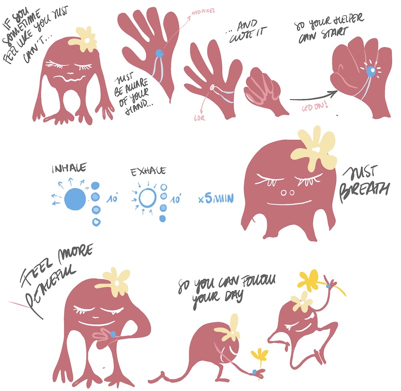
We made a little sketch in order to clarify how the components will be placed in a soft circuit made by conductive thread so it could be on the hand.
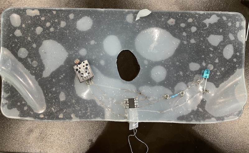
Here is a little video on how I sew the circuit on a layer of silicone (as it can't be in touch with the skin). It was hard to embroid the components to it, as it seemed that they weren't fully attached. But after finishing and connecting it to the batterie it worked!! but just until we put it on the hand were it broke haha.
So after this first try we decided to sew the circuit in a normal glove, so that at least we could see how the circuit worked embroided. It wasn't as dificult as the silicone and the connections were more reliable. However something wasn't very good in contact so after powering it, sometimes it worked, sometimes it didn't. But sometimes it did! haha
TATOOING MYCELLIUM SKIN
Of course I needed my living experimentation that I did back home. I took with me some conductive ink (from Bare conductive) and some silicone layers as the ones as Arantza and I used. I principal idea was tatooing the silicone, as I am a tatooist, and paint my own circuits. First I tried mixing the two inks, but I realized from previous experiences with the conductive ink, that it already has a lot of resistance, so mixing it with another one, will give a lot more. However the silicone doesn't respond very good with tattos as it doesn't welcome the ink and leave it inside.
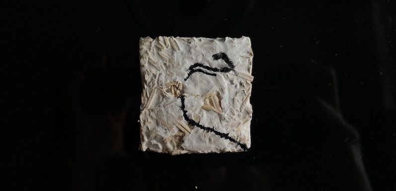
But, as I was at home, in the same room were all my first mycellium test were made; I had a bunch of dried pieces that were asking me to tatoo them. So I thought that skin electronics are not closed to human skin, if not that it can embrace other living organisms skins such as mycellium. And morever as the pieces that could be used are already dead there will be no harm in the organism. So I decided to give it a try: first a test how the needle worked in fungi skin as I didn't know if it would break it or not. As it worked incredibly good (so pleasant too), I tried with the conductive ink a simple negative and positive circuit to connect a LED. I couldn't test it as I forgot some jumpers to connect it to the power bank but as soon as I'm bck to the BDC, I'll try it.
Research
Useful links
- Loes Borges. Capacitive crystals
- Catherin Euale
- Ana Laura San Roman -Jessica Stanley