5. E-textiles
This week is all about E-Textiles and to learn the basics. It took a bit of effort to scale down my knowledge and go back to basics, but that's great. Fab Academy demanded making your own PCB's which was mostly a hassle, but great fun when it actually worked. But mostly it took up so much time... Glad to let the board making be done by pro's and use their boards to work with E-textiles.
The basics
Working with electronics
Microprocessors and computers are purely digital components. But when it comes to our wearable projects, we most likely want them to interact with the world we live in. This means having to deal with different kinds of electronic languages: analogue and digital. One could state that working with electronics means having to deal with these analogue and digital signals in the form of inputs as well as outputs.
What is a digital / analogue signal?
The world is analogue, thankfully.
Our world has an infinite amount of colours, with an evenly infinite amount of gradations. There are so many that even our eyes cannot seem to tell the difference. That's fine. Same goes for tones we can(not) hear, smells we can(not) smell, ...
The one thing all of these analogue signals have, is that they have infinite possibilities.

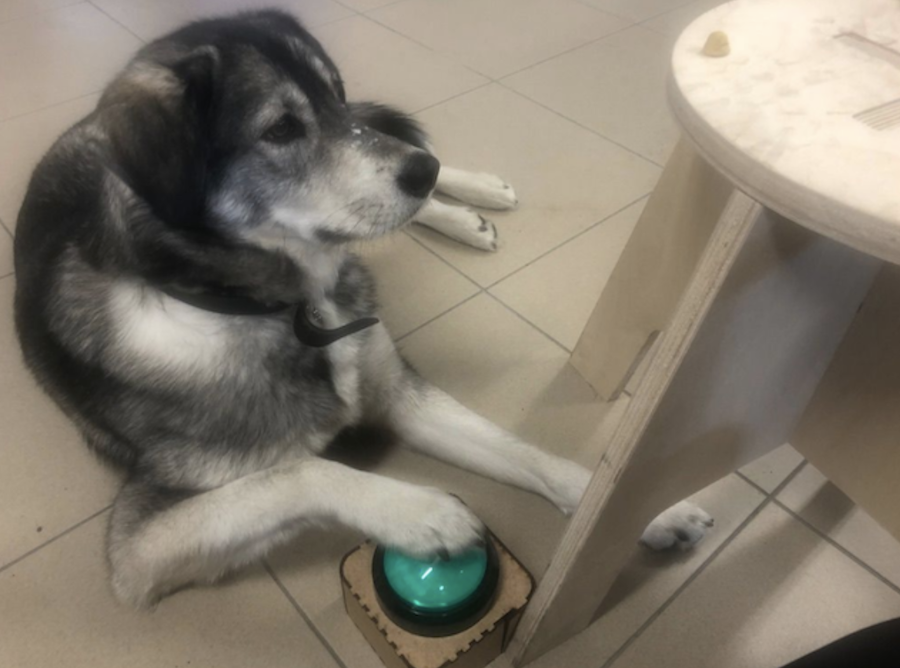
Digital signals on the other hand are rather simple and straightforward. They have a limited set of values, therefor they ar finite. Mostly you have two: 1 and 0. (But in coding they could be defined as any number, as long as it's not infinity or ∞) One value that pops up quite often is 255 as we refer to this value when labeling colours. The easiest example is an on/off switch: on gives power to your project, off allows you to save power and go do something else. For example, you might want to use big buttons to train your dog. Works like a charm!
Combining analogue and digital
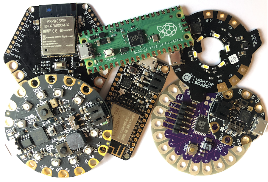
In come the microcontrollers. These little beasts are small computers that are able to read an analogue input and all the shades of gray that defines the world we live in. (Or at least, once we've programmed it correctly.) These readings are possible because most microcontrollers have a device built in that allows us to convert analogue signals into values. Upon defining these values, we will be able to use them in our program later on to declare a decision. This device is called the ADC or Analogue to digital converter.
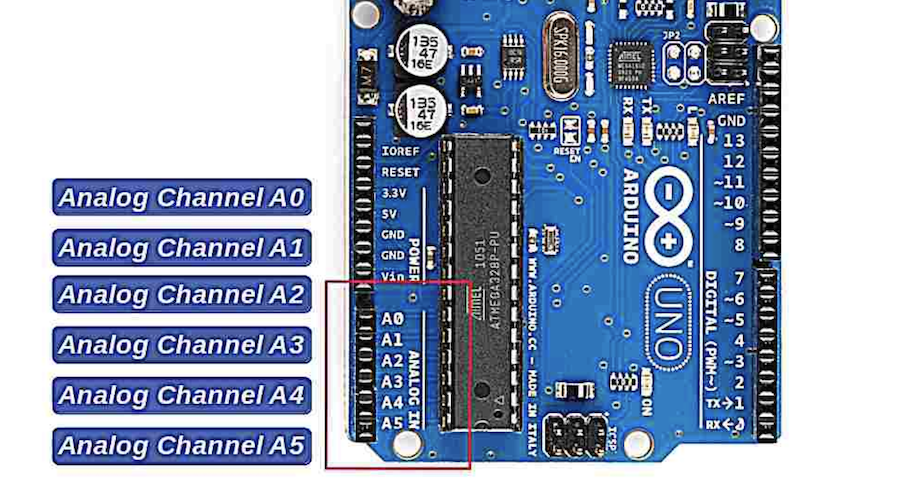
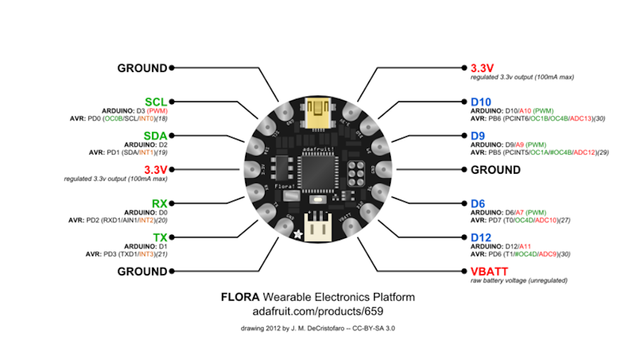
You can recognise the ADC on your controllers by looking for pins that have an 'A' before there pin number. On Arduinos they are clearly marked and grouped together as 'Analog in' with 6 A-pins.
When in doubt, you can always look up the pin-out of your microcontroller and check. This is the pin out for the microcontroller I'll be using for this assignment.
Sensors
In order to interact with you surroundings, you need senses. Humans have five basic senses (seeing, tasting, touching, hearing, smelling). But there are far more that allow us to live the way we do. and Proprioception for example allows us to have a sense of space and know were we are. Humans also have neuron sensors that detect our movements. Kinetic sensors that allow us to control our muscles. And so on. I find it fascinating!
In electronics a sensor is a tool (module, device, ...) with a mission set out by other electronics as a sensor can never work by itself. It's mission is to detect changes in its environment, gather the data the change generates and send it to other electronic. This particular piece of electronics will most lickely be a computer processor like your microcontroller.
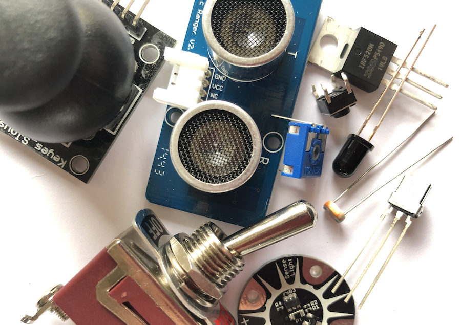
You have sensors in different sizes and forms and you can make them yourself as well! Let's get started.
Analogue sensor
Under pressure
Children in the lab often ask how a trackpad works. Basically it's a pressure sensor that detects different gestures as well as hidden buttons underneath to detect when you click left or right. I will focus on the first sensor and make my own pressure sensor.
(Simple bare) necessities of life?
Step-by-step
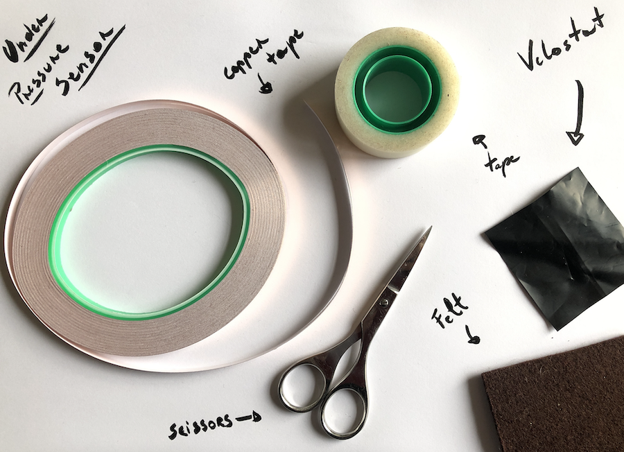
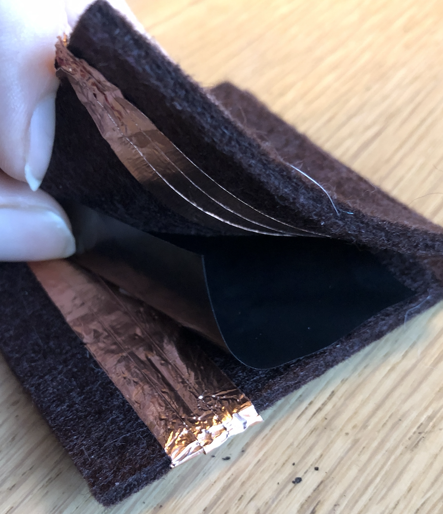
- Cut out two evenly big pieces of felt.
- Stick on the conductive copper tape to that both pieces have a small overlap when putting them on top of each other. Keep in mind to face the copper tape to each other!
- Cut out a piece of Velostat that's a tiny bit smaller than the felt pieces.
- Optional: sew the two pieces together. (For this small project I used double sided tape.)
- Ta da!
Digital sensor
Hook the loop
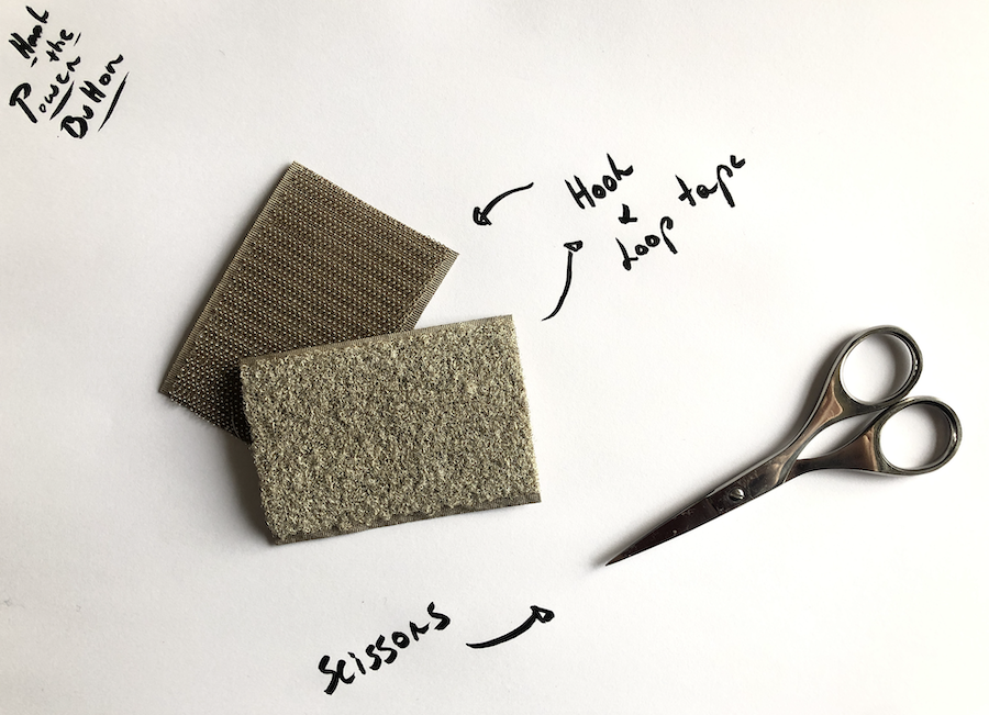
For the digital sensor I kept things rather simple. Upon ordering a bit of electronics for the Fabricademy I discovered conductive hook and loop tape. It's super simple, but it works extremely well. I'm impressed and I will most definitely continue to use this material for future projects!
Necessities
Step-by-step
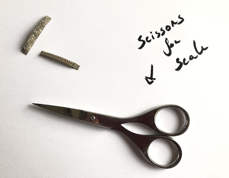
- Cut off a small piece of both the hook and the loop side.
- Ta da!
Hook up Flora
For this project I'm not working with an Arduino but with a Flora module by Adafruit. The Flora module is a wearable microcontroller. It's sewable as well which makes it perfect for wearables.
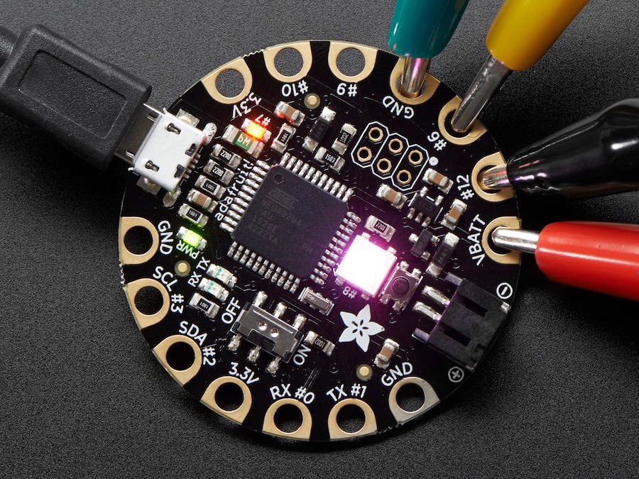
With it's Atmega32U4-chip, it acts like an Arduino and you can code it in the similar way as Arduino. Make sure to install the correct library in the software, select the board and port. Follow the Adafruit tutorial and you're all set!
Attach Flora's senses
To read the analogue input in the serial monitor in Arduino using the Flora, we need to connect the sensor to the Flora microcontroller.
For this set-up I used alligator clips which you can find in nearly any hardware store were they sell electronics as they are often used to test circuits. In order to detect the input from your analogue sensor, you will also need a resistor that's quite 'resisting'. Look for a resistor with 50K - 50M Ohm. The resistor value affects the sensitivity of the touch sensor.
If you don't know the colour codes by heart, have a look here
Necessities
The attach the Flora you need the following pieces, as well as the FLora itself of course.
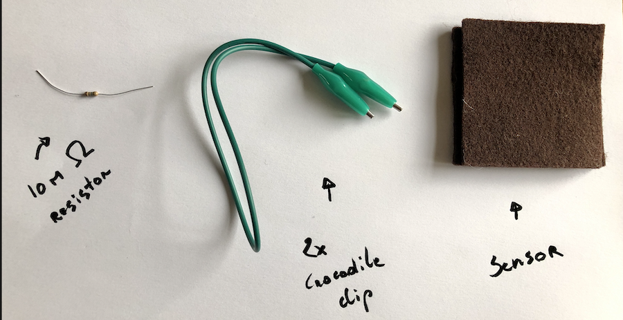
I used a 10M Ohm resistor with a 5% tolerance.
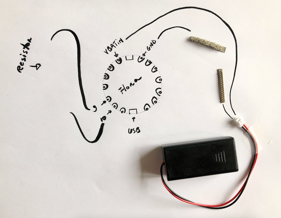
Schematics
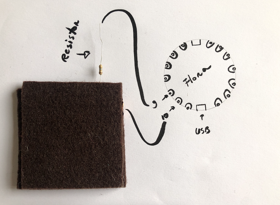
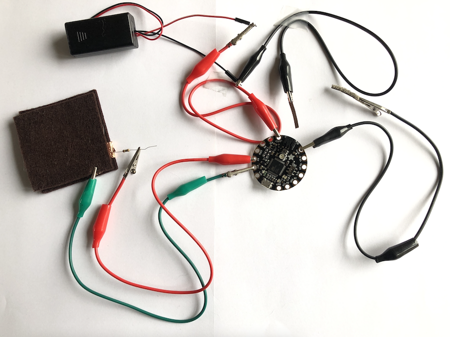
Step-by-step
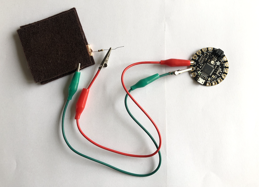
- Attach the resistor to a crocodile clip, attach the other end to the Flora. (I used pin 9.)
- Attach the other end of the resistor to the copper tape on the sensor, make sure it's connected to one side only.
- Attach the second crocodile clip to the other side of the pressure sensor, also touching the copper tape but not each other, and attach the other end of the crocodile clip to your Flora. I used pin 10 in the example.
- Ta da!
Test the sensor
To test the sensor, I used an existing library in that I added in Arduino.
I used the example code and adapted it to my sensor by changing the pins as well as the output name. I named it sensor1 in order to be able to add other sensors rather quickly in the future.
    #include <CapacitiveSensor.h>

        CapacitiveSensor   cs_9_10 = CapacitiveSensor(9,10);

        void setup()
        {
          cs_4_2.set_CS_AutocaL_Millis(0xFFFFFFFF);     // turn off autocalibrate on channel 1 - just as an example
          Serial.begin(9600);
        }

        void loop()
        {
            long start = millis();
            long total1 =  cs_9_10.capacitiveSensor(30);

            Serial.print(millis() - start);        // check on performance in milliseconds
            Serial.print("\t");                    // tab character for debug windown spacing

            Serial.print(sensor1);                  // print sensor output 1

            delay(10);                             // arbitrary delay to limit data to serial port
        }
Upon reading the input in the serial monitor it's clear that the sensor works and generates input. Great!
Attach the battery
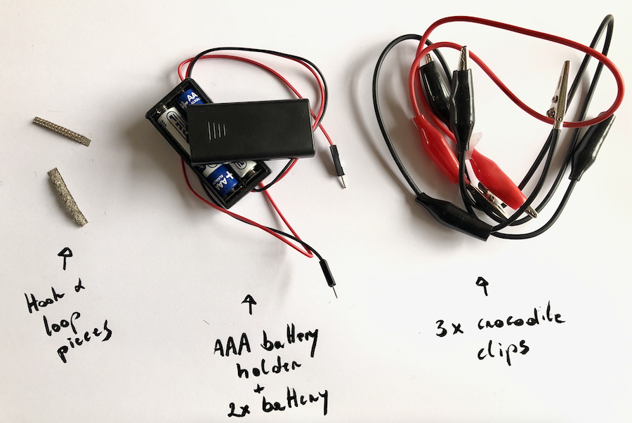
In order to use the set-up on it's own, you need a battery pack. I used a small one with two tripple A batteries (3V) which is perfect to power both FLora as well as the NeoPixel.
Necessities
Schematics
Step-by-step
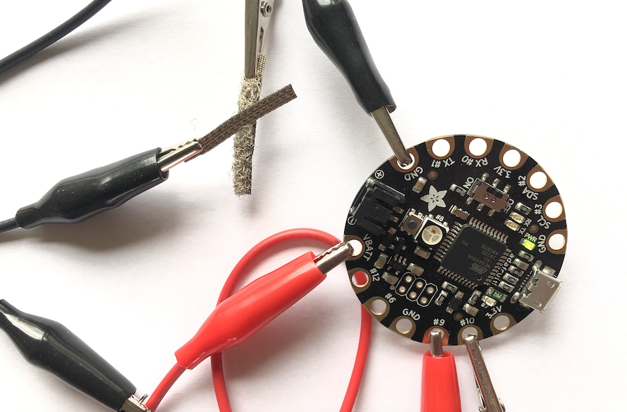
- Attach a crocodile clip (I would suggest to use two black ones) to both pieces of the hook and loop tape we cut earlier.
- Attach the other end of one of the black clips to the battery holder, on the black wire or ground cable/clip depending on your battery holder. (Doesn't matter if you pick the hook or loop piece.)
- Attach the second black clip to the Flora board. Check the board for one of the ground (GND) pins and attach the cable to one of these. (Doesn't matter if you pick the hook or loop piece.)
- Take a third crocodile clip, preferably a red one. Connect it to the red wire of the battery holder and on the VBATIN pin of the board.
- All set and ready to go!
Test the sensor
Testing a simple digital sensor is rather simple. In this case you simple connect both pieces of hook and loop tape and your board should power up. At least if you don't forget to put in batteries :-)
Time to cut battery power temporary now by detaching the hook and loop sensor and code our Flora to work as a stand alone project.
Code Flora's senses
With all the sensors and cables in place, it's time to code. Attach your Flora to the computer using a USB-cable. (Make sure the battery is not connected!) and start the Arduino software. Your board's power on LED should light up.
In order to programme the I used, you will need to install the NeoPixel library if you intend to use it.
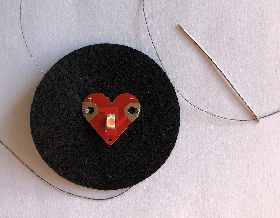
As we've already used part of the code to test the pressure sensor, it's a matter of adding the NeoPixel. First we need to hook it up to the board, but it's up to you if you rather use the one on the board of the simple LED on pin 7.
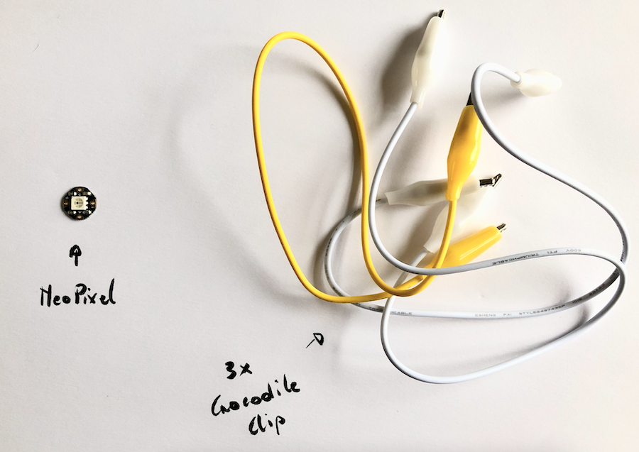
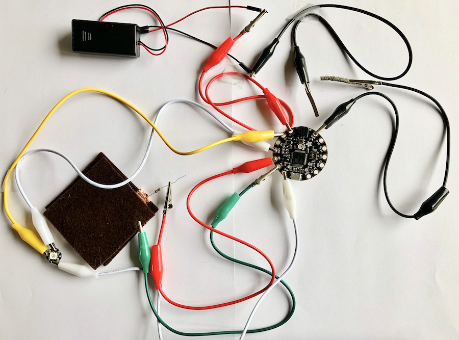
I hooked up the NeoPixel with three crocodile clips. The first one going from the + side of the NeoPixel to the 3,3V pin on the board. The second going from the - pin to a ground pin. The third one going from pin 12 to the NeoPixel on the side of the inward facing arrow.
All done!
Now it's a matter off adjusting the code by adding the NeoPixel and adjust the code so that the sensor input (sensor1) defines the colour of the pixel.
This is it:
  #include <CapacitiveSensor.h>
  #include <Adafruit_NeoPixel.h>

  CapacitiveSensor   cs_9_10 = CapacitiveSensor(10, 9);

  #define LED_PIN    12
  #define LED_COUNT 1

  Adafruit_NeoPixel strip(LED_COUNT, LED_PIN, NEO_GRB + NEO_KHZ800);


  void setup()
  {
    cs_9_10.set_CS_AutocaL_Millis(0xFFFFFFFF);     // turn off autocalibrate on channel 1 - just as an example
    Serial.begin(9600);

    strip.begin();           // INITIALIZE NeoPixel strip object (REQUIRED)
    strip.show();            // Turn OFF all pixels ASAP
    strip.setBrightness(15); // Set BRIGHTNESS to about 1/5 (max = 255)
  }

  void loop()
  {
    long start = millis();
    long sensor1 =  cs_9_10.capacitiveSensor(30);


    Serial.print(millis() - start);        // check on performance in milliseconds
    Serial.print("\t");                    // tab character for debug windown spacing

    Serial.print(sensor1);                  // print sensor output 1
    Serial.print("\t");

    strip.setPixelColor(0, strip.Color(0, 0, sensor1));

    strip.show();

    }
After uploading this code your NeoPixel should change it's colour depending on how hard you press the button. I only changed one value for now, but you could add another sensor or use the same input to change the colours of all three led's in you NeoPixel by using the follow code "strip.setPixelColor(, strip.Color(sensor1, sensor1, sensor1));".
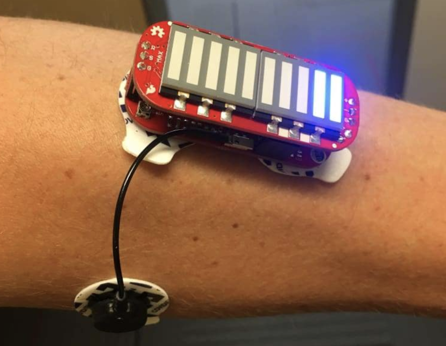
Time to detach the Flora and reconnect the battery. If all went well, your board and NeoPixel should power up and the light will change upon applying different pressures to the sensor.
Good luck!