7. Computational Couture
Research and inspiration
During the digital bodies week I already wrote that I'm not into bodies. It shouldn't be too surprising that I'm not into couture either. Oops! However, computational thinking is is right up my alley! Thankfully :-) Fab academy made me explore loads of different software packages last year and I discovered then and there that grasshopper is not my cup of tea. I discussed this with Ceciilya and she gave me an okay go for working with a different software package. So going off road and go full on computational coding using Processing. Yeay! (At least for me ;-))
Nature is where everything starts. There’s beautiful growing patterns to be found all around. Things like algae, corals, ...
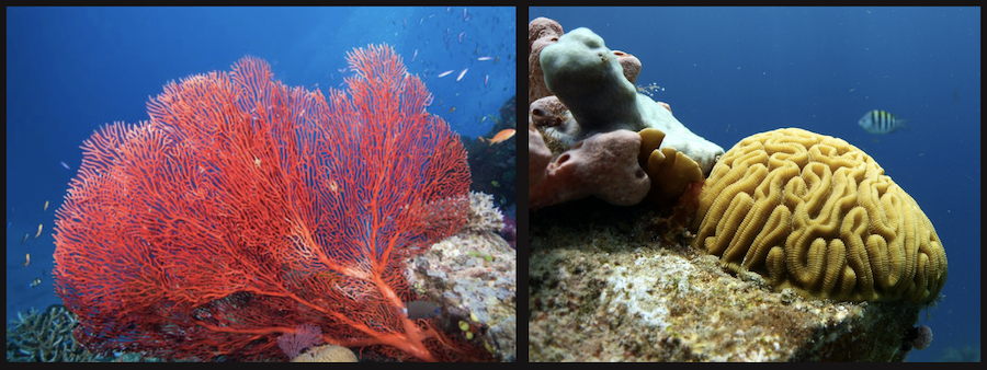
Beautiful, no?
Of course I have to mention Ernst Haeckel. He did a bit of everything, he was a zoologist, philosopher, professor, marine biologist, … and and artist! What a combo! He discovered and named so many new species, relating and connecting them and by doing so creating all new genealogical trees. I would’ve loved talking to him. Cause he created some of the most beautiful research drawing ever. Like really, ever. No doubts there. Ever. Period 🙂
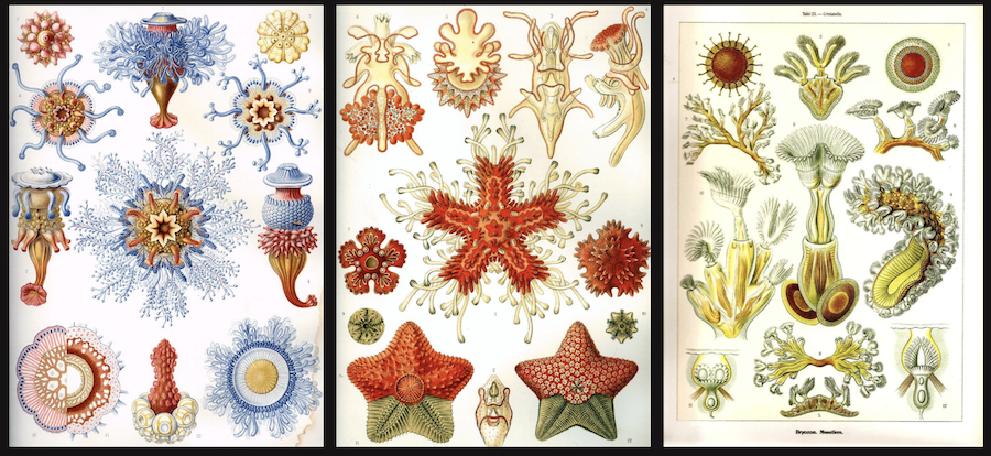
These drawings have been an inspiration forever. I love the combination of science and art and bringing the two of them together. If you’ve never heard of him, look him up!
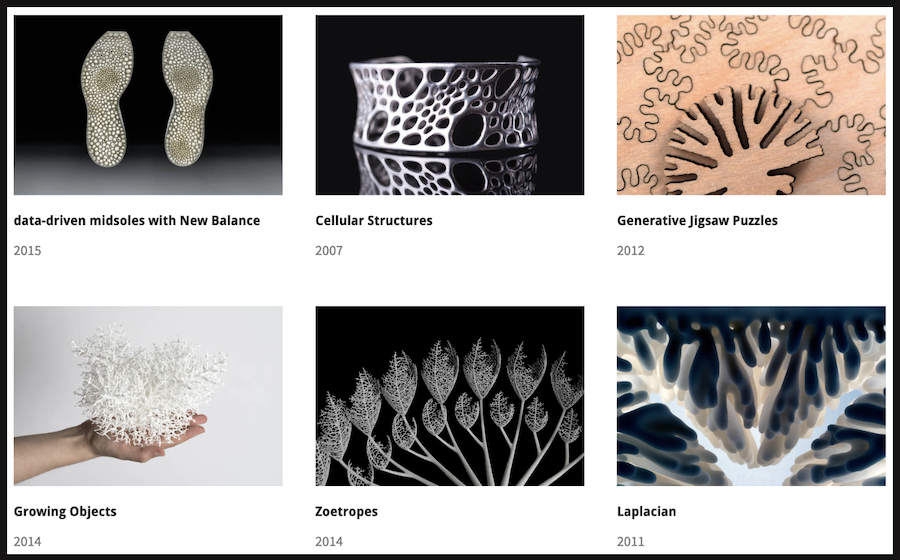
And I cannot write about inspirations for computational coding without mentioning Nervous systems. Nervous System is a generative design studio that works at the intersection of science, art, and technology.
Founded by Jessica and Jesse they’ve been making beautiful things using code. They start from computer simulations to generate patterns, taking them through digital fabrication processes to create actual objects. It’s mind blowingly beautiful!
Code your plastic
My goal: create a coral growth in code and 3D-print it on fabric. Phew, with our goal in sight, it’s time to find the right help. Luckily my best friend Kurt is a bit of a coding wizard, so he offered to help me dive into this. Stumbling onto Codeplastic we found everything we needed to create a first draft.
Write your code
Basically what we set out to do was pretty straightforward: create a differential line growth and export it as a curve. Finding inspiration here and [here](https://natureofcode.com/book/chapter-10-neural-networks/](https://www.andylomas.com/cellularFormImages.html) it was time to get coding. But not without making a cup of coffee first, we wouldn’t skip preparing for our final projects whilst doing this assignment now wouldn’t we?
With the coffee at hand, let’s open processing and start a new project. The whole goal is to create a line or a circle that grows, randomly and infinitely. But with respect for keeping a distance from the closest bends. Each bend has nodes, points of a curve let’s say. New nodes will be added on the line randomly between a pair of existing nodes, but you don’t want your neighbours building in your back yard? So each new pair of nodes will require for the original line to grow in different directions, keeping the neighbours happy by keeping a set distance. Same way the corals grow: in their respectful place and at a distance from their neighbour, but always leaving room for more coral. In written text it seems more complicating than it actually is, thankfully!
First, we need to set out a few parameters. These will be necessary for defining our line, the growth, at what speed, ….
// PARAMETERS
float _maxForce = 0.6; // Maximum steering force
float _maxSpeed = 1; // Maximum speed
float _desiredSeparation = 9;
float _separationCohesionRation = 1;
float _maxEdgeLen = 4;
The “void run()” is where you define your functions and is the main part of the code. Same as in arduino.
void run() {

// this is the function that defines the nodes

for (Node n : nodes) {
n.run(nodes);
}
growth();
}
void addNode(Node n) {
nodes.add(n);
}
void addNodeAt(Node n, int index) {
nodes.add(index, n);
}

// the following lines of code define where the nodes land

void growth() {
Node lastNode = nodes.get(0);

for (int i=0; i<nodes.size()-1; i++) {
  Node n1 = nodes.get(i);
  Node n2 = nodes.get(i+1);
  float d = PVector.dist(n1.position, n2.position);
  if (d>maxEdgeLen) { // Can add more rules for inserting nodes
    int index = nodes.indexOf(n2);
    PVector middleNode = PVector.add(n1.position, n2.position).div(2);
    addNodeAt(new Node(middleNode.x, middleNode.y, maxForce, maxSpeed, desiredSeparation, separationCohesionRation), index);
  }
}

// these lines of code make sure the new nodes and the old ones are connected with a line

}
void render() {
for (int i=0; i<nodes.size()-1; i++) {
PVector p1 = nodes.get(i).position;
PVector p2 = nodes.get(i+1).position;
line(p1.x, p1.y, p2.x, p2.y);
if (i==nodes.size()-2) {
}
}
}
These lines of code will run the program and refer to everything you’ve defined beforehand.
PVector separate(ArrayList nodes) {
PVector steer = new PVector(0, 0);
  int count = 0;
    for (Node other : nodes) {
        float d = PVector.dist(position, other.position);
    if (d>0 && d < desiredSeparation) {

PVector diff = PVector.sub(position, other.position);
  diff.normalize();
  diff.div(d); // Weight by distance
  steer.add(diff);
  count++;
  }
}

  if (count>0) {
  steer.div((float)count);
  }

  if (steer.mag() > 0) {
  steer.setMag(maxSpeed);
  steer.sub(velocity);
  steer.limit(maxForce);
}

return steer;
}

PVector edgeCohesion (ArrayList nodes) {
PVector sum = new PVector(0, 0);
int this_index = nodes.indexOf(this);
  if (this_index!=0 && this_index!=nodes.size()-1) {
  sum.add(nodes.get(this_index-1).position).add(nodes.get(this_index+1).position);
}

  else if (this_index == 0) {
sum.add(nodes.get(nodes.size()-1).position).add(nodes.get(this_index+1).position);
}

  else if (this_index == nodes.size()-1) {
sum.add(nodes.get(this_index-1).position).add(nodes.get(0).position);
  }
sum.div(2);

return seek(sum);
  }
}
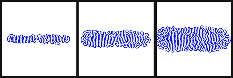
When all goes according to plan, you should end up with some very beautiful growing lines when you press the play button 🙂
If you would like to be able to export screenshots during the growth, you can simply add these lines of code in your “void run()’ command:
void exportFrame() {
    saveFrame(day()+""+hour()+""+minute()+""+second()+".png");
}
This will leave you a print screen of every node added.
Export your curve
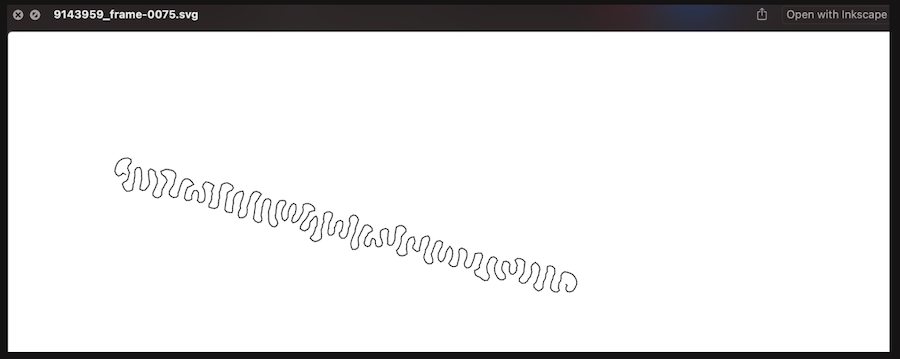
With the following lines of code in place, Processing will give you an svg file to work from.
First you have to import the svg library. Loading a library needs to be done at the beginning of your code. It only takes a simple line of code:
import processing.svg.*;
Here you can find a lot more information on the different possibilities this library gives you. For this assignment I wanted to go for an export of a single frame, but see the animation on my screen as well. Cause really, it’s too beautiful to run it hidden in the back :-)
The code and explanation in the comments (the lines with // in front):
boolean record;

// this defines the size of the window where your animation will run
void setup() {
  size(400, 400);
}

// colors of the window and the color and size of your line
void draw() {
   background(255);
   stroke(0, 0,255);
   strokeWeight(4);

// this defines how your svg will be saved
 strokeJoin(ROUND);
     if (record) {
    beginRecord(SVG, day()+""+hour()+""+minute()+""+second()+"_frame-####.svg");

}

// in order to avoid having thousands of svg's, you might want to add a line of code that only saves when you press a key
// in my case the letter s

void keyPressed() {

  if (key == 's') {
    _diff_line.exportFrame();
     record = true;
  }
}
While this gives you an svg, so not a 3D file, it only takes two smaller steps to create a 3D-printable file from this point.
In the future I might want to try and use a library based on the nervous systems OBJExport, but at the moment this doesn’t seem to be compatible anymore.
SVG to printable file
The path is there, great! Now you need to have a software that can create a closed offset curve of the path exported. I use Illustrator as it’s been my go to software for as long as I can remember, but the steps are similar in Inkscape, which is free downloadable vector software.
The steps are fairly simple.
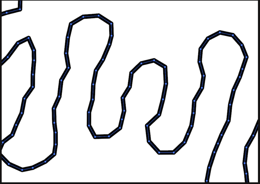
First you open your svg in your software. If you zoom in, you will see there is only one path. In order to print is, you will need a double one. The logic behind this is that a 3D-printer fills the gaps between two lines in order to create an object. One open line doesn’t do the trick. To achieve this, you will need to create an outline.
-
The next step would be to create an offset of your original path. This means that you create a closed path around the selected path with the parameters that you choose. In Illustrator this is hidden under Object > Path > Offset Path…
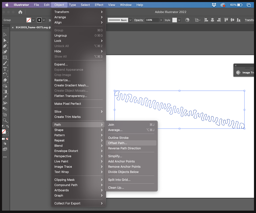
This leaves you with one closed path. Save your file as an svg and you’re all set for Tinkercad!

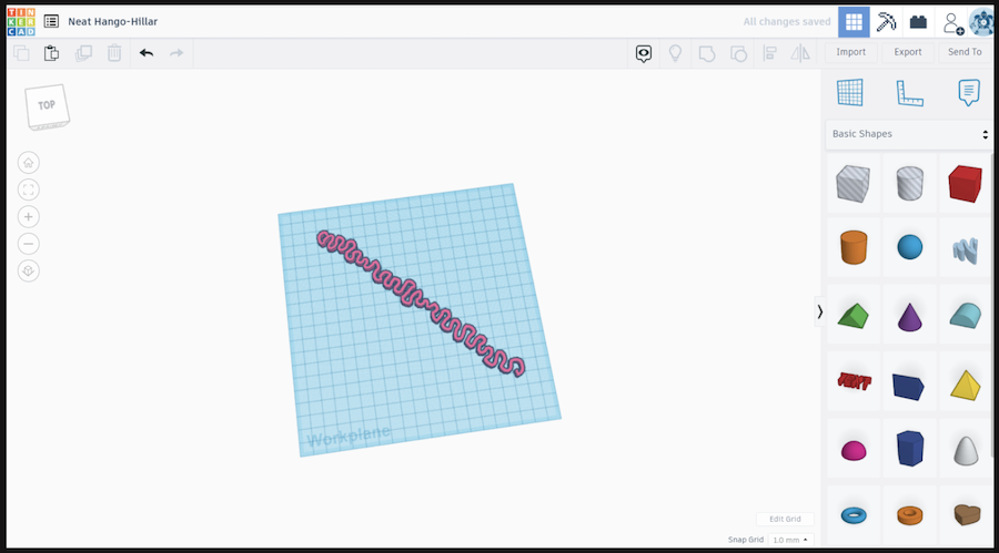
In Tinkercad you can make a new project and then select “Import” on the top right. You can simply select your svg and it will be imported onto your workplane. Depending on the size and number of pen point on the curve, this could take a while.
But once loaded, you should have something like this.
Export it to an obj, run it through the software you use for exporting the gcode necessary for your printer and go heath up the printer :-) I described the steps for my printer here.
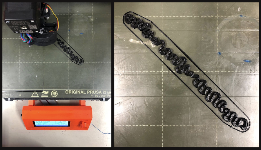
I did a couple of tests, all with fairly flexible TPU filament. The black tests are done with ColorFabb nGen Flex with a temperature of 260 degrees Celcius and a bed temperature of 85 degrees Celcius.
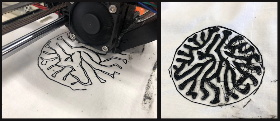
Of course there was a test done on some cotton as well with a different linear growth model. Isn’t is gorgeous?
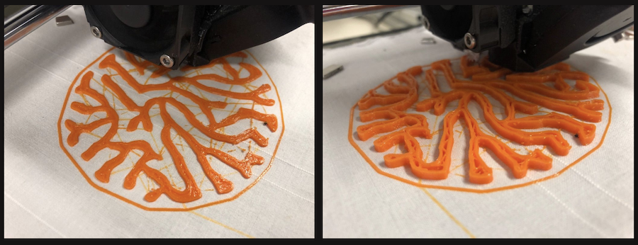
But corals aren’t black, aren’t they? So here’s for orange! The orange filament is Filaflex, the nozzle has a temperature of 240 degrees Celcius and the bed a temperature of 60 degrees Celcius.
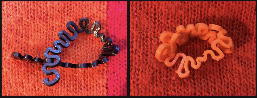
Aren’t they amazing? Did I mention they’re flexible as well? Yes baby! Flex and stretch it like you mean it!
Make your own 🙂
You can find the whole processing file here.
But if you only want to print, go with the coral OBJ number 1 and coral OBJ number 2
Enjoy tweaking!