2. Digital bodies
Research
The second week of Fabricademy journey has begun!
After the lecture on Digital Bodies, it left me a little bit overwhelmed with the volume of the information and the beautiful examples of digital sculptures.
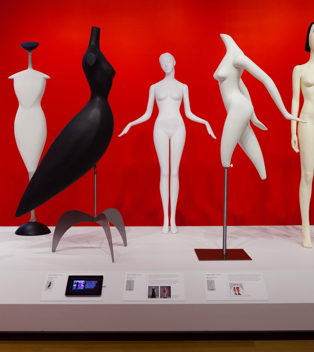
Ralph Pucci: The Art of the Mannequin
References & Inspiration
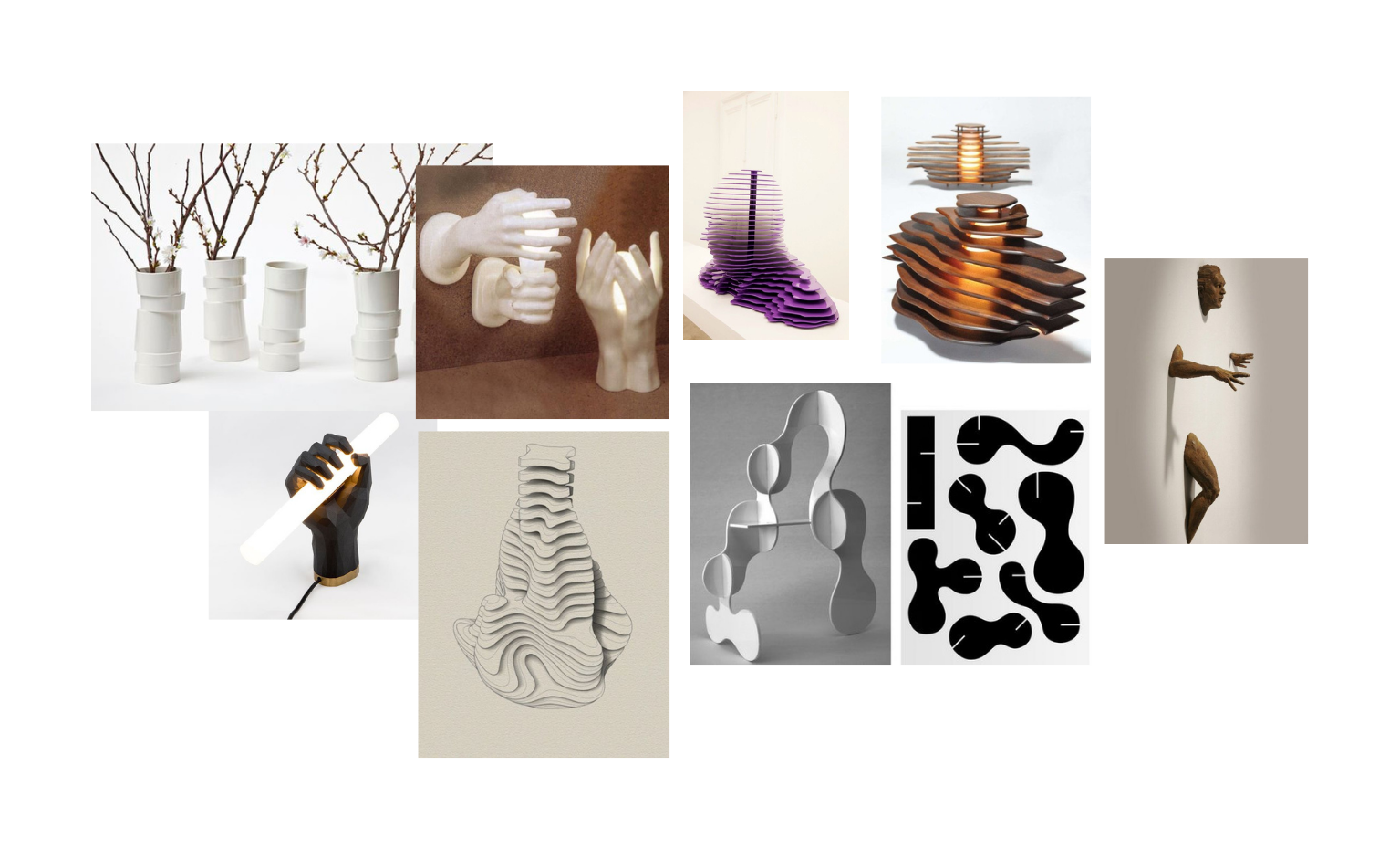
Right from the beginning, I wanted to reproduce the shape of my hand and integrate a simple circuit to use it as a lamp. Here is the moodboard that represents a selection of works that formed the inspiration for the creation of the desired product.
Process and workflow
3D scanning's process
3D scanning is the process of analyzing an object or environment, and collecting data about its appearance. The scanning tool then creates a 3D digital object, which can then be replicated with a 3D printer, CNC mill or it can be used for digital display.
Professional 3D scanning can be divided into two categories: contact and non-contact. Contact scanning places the object on a precision surface and probes the object with touch. Non-contact active scanning uses light to probe an object, while non-contact passive scanning detects ambient radiation.
Sometimes these types of 3D scanning require expensive hardware and software, but a more accessible option is to 3D scan with photogrammetry, for example, with a smartphone app. There are a lot of different apps, the full list you can find here.
I used the Polycam App for scanning my hand. For a better result I took a white A1 paper, made a hole in the middle of it and with the help of my colegues scanned my hand. The program takes multiple pictures. It is important to take as many as possible and from different angles. After this takes a few minutes and the 3D object is generated. It can be shared as a USDZ file. I used an online convertor Aspose to transform it in a STL file.
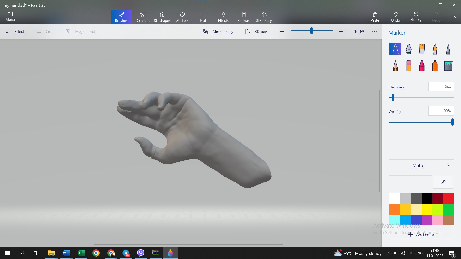
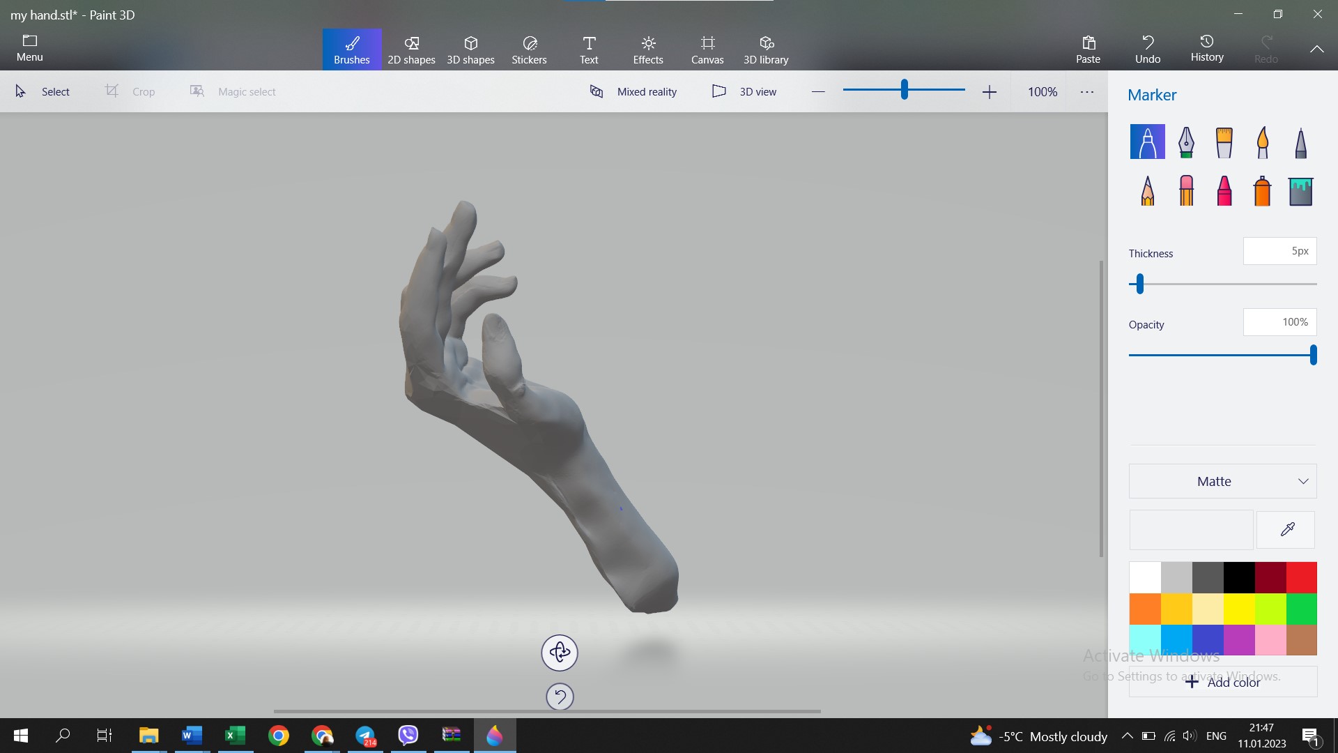
The detalization of the hand is not such accurate. But it was fun experimenting with this app.
MakeHuman
So, because the scanning went not so well, I started to work on the process of creation of an avatar in MakeHuman - an open source 3D computer graphics middleware designed for the prototyping of photorealistic humanoids. This software allows you to create a personalized avatars, with the shapes and sizes you want, also with the possibility of choosing different features, position of the body (running, sitting, etc.).
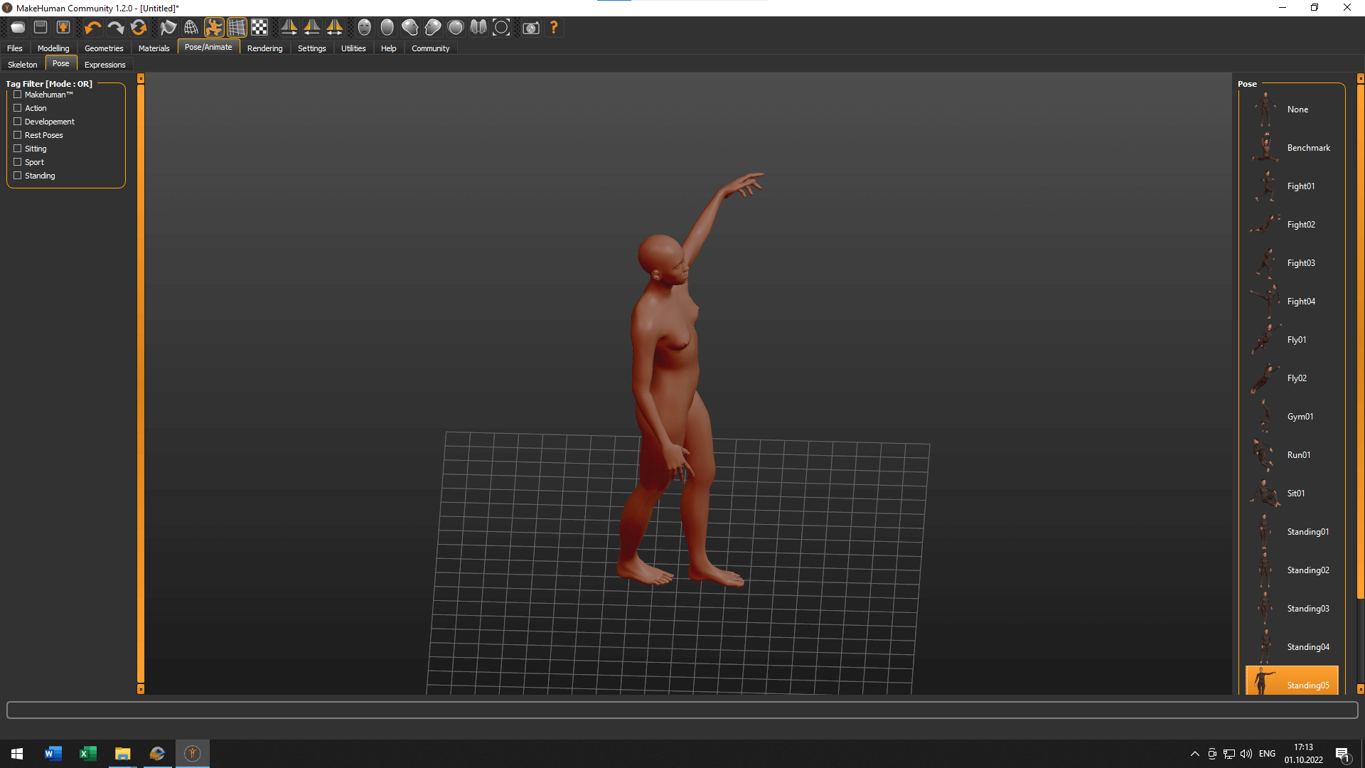
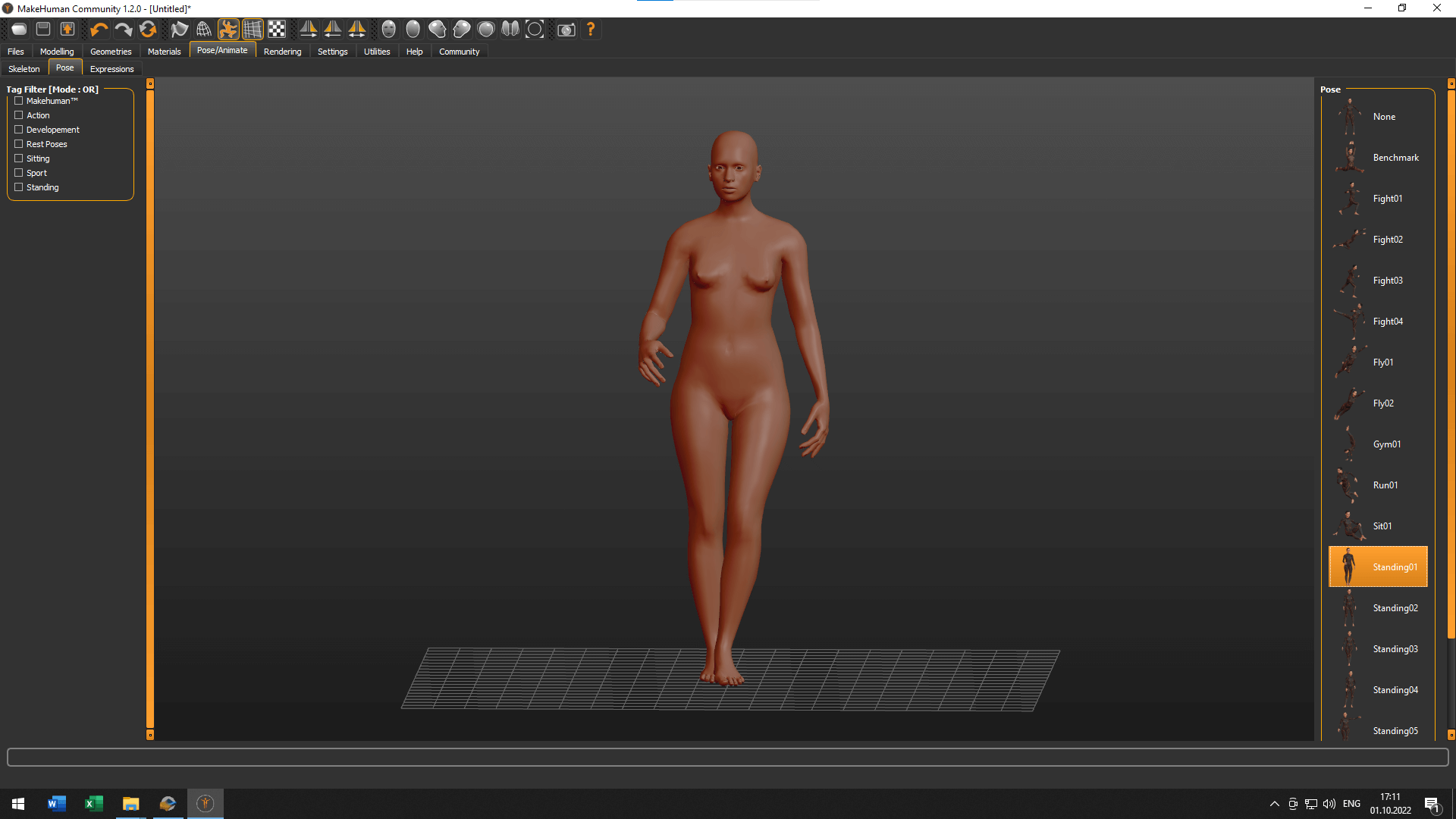
After watching the Make Human tutorial with Diane Wakim, I played a little with this software and gave it my parametres to make it similar to me1.
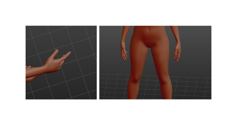
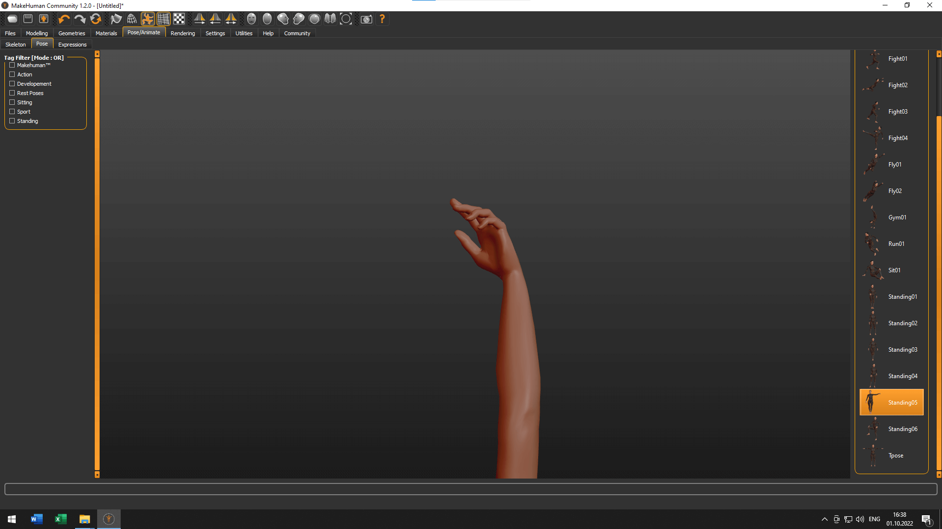
I liked the idea to make a functional object out of some part of the body, so I choose to make a hand sculpture that will hold a light bulb. I selected the position that had a more relaxed position of hands, you can see it below.
Rhino
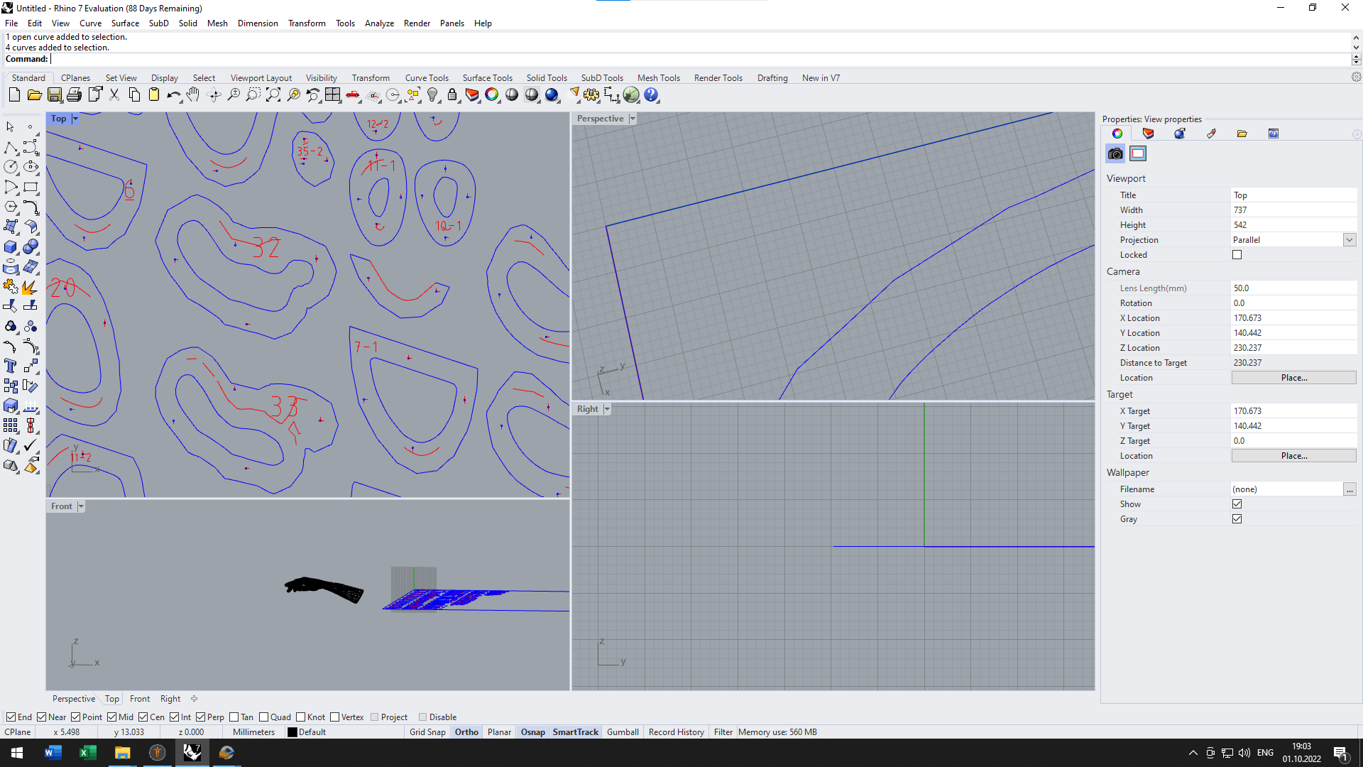
After creating the avatar1, I exported my model in the formats .OBJ and .STL to be able to open them in Rhino, afterwards. I used Rhino to cut the parts I did not need to laser cut, keeping only the left hand of the body2. Using various tools like Line, Polyline, Rotate, Trim, Cap, MeshToNURB, I got the following result.
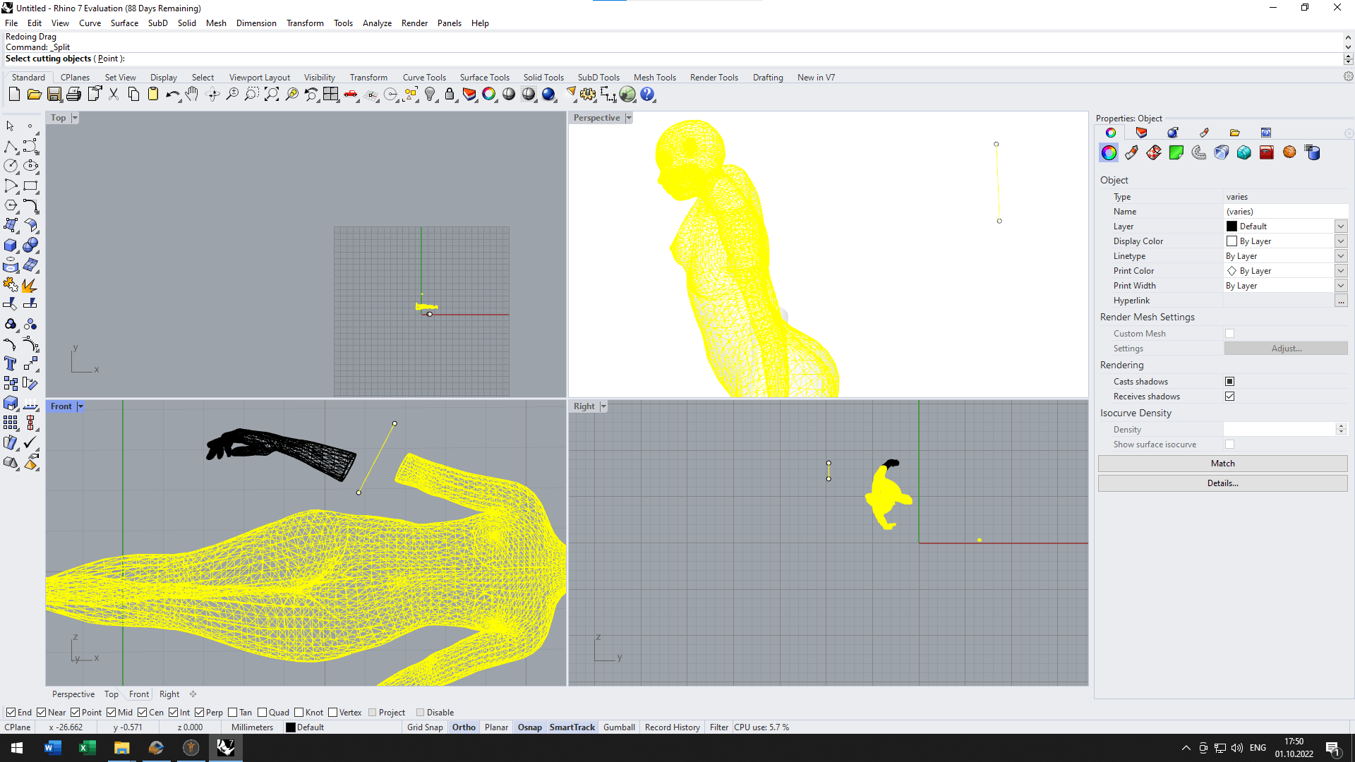
Before importing the 3D model to Slicer, I corrected the opening of the fingers in Blender. There were too little space between the thumb and the rest of the hand to fit a light bulb.
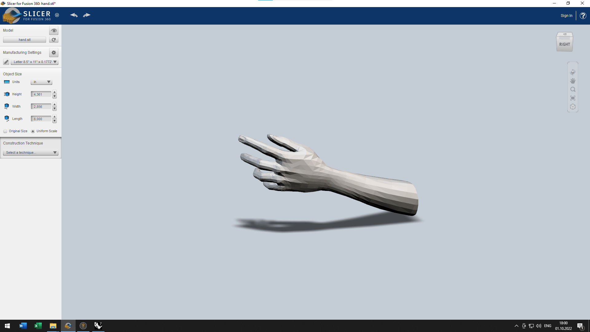
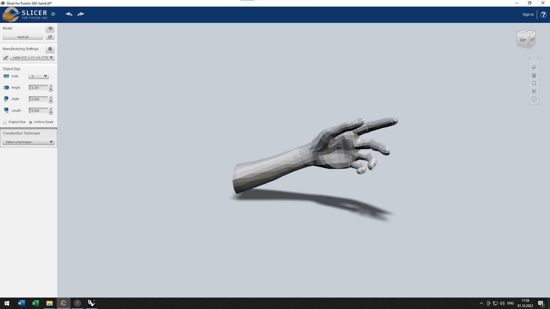
Slicer
The next step is to use the exported file in Slicer for Fusion 360 to obtain the needed pieces for cutting.
We set the needed size of the board, 740mm x 1520 mm and height = 4 mm. After this I experimented with diferent types of construction (stacked slicing, interlocked slices, curve construction) and the directions of slices. But, because my body part was not so big (a hand with tiny fingers) the best of the option was to choose the stacked slicing, and do it by diagonal to make it more dinamic.
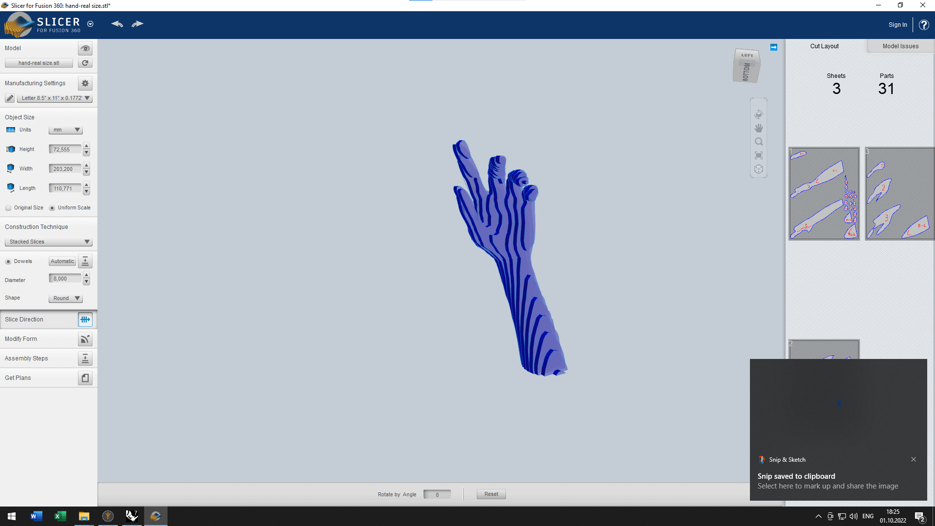
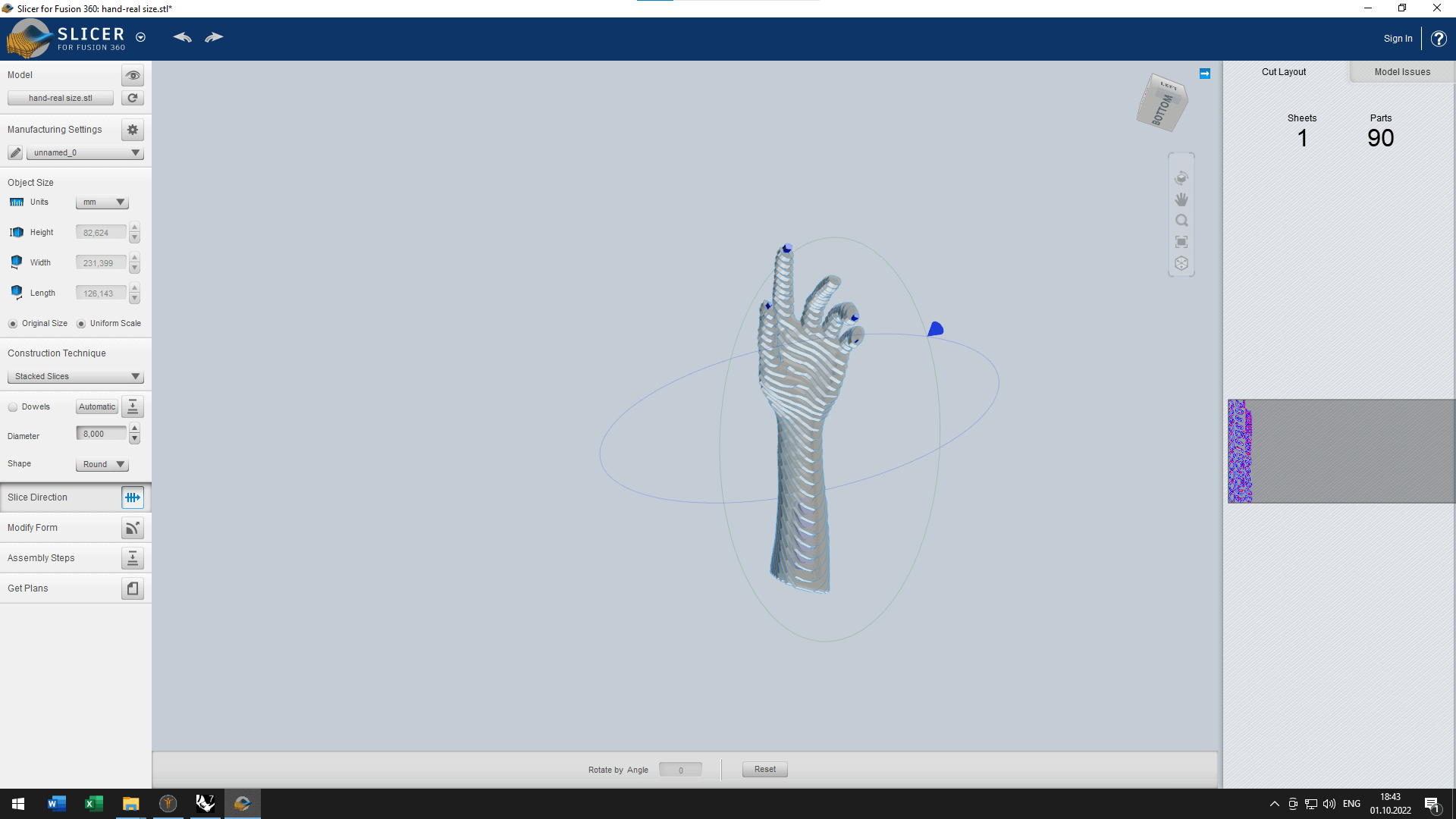
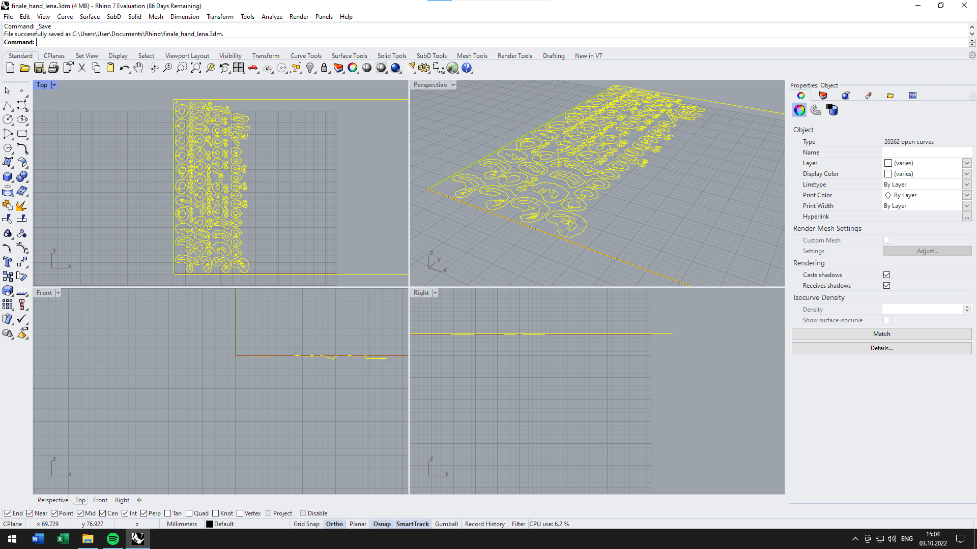
Then saved the final file as a [.dxf] file ready to be cut3. These are the final pieces I sent to the laser cutting machine. I still needed to import once again in Rhino to make sure that the holes in the middle of my hand are wide enough for the cable.
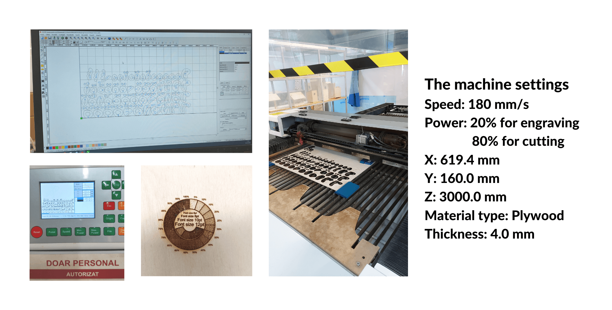
After preparing all the files and cheecking the simulation of the assembling, I went to our FabLab to use the laser cutter. There I got the help of the local instructor and together with him we prepared the needed surfaces for cutting, set the parameters, prepared the files and started to cut.
We experimented with the speed and saw that if we use a 6 mm/s speed, the pieces will cut very fast and easy.
Thanks to the size of my work, there was no need of a big sheet of polywood. I had 129 little pieses. The laser cut the pieces for about 40 minutes.
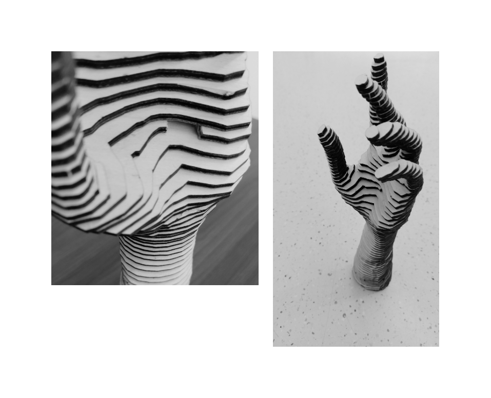
Assembling
 The fabrication process was basically glueing the parts based on number. It was tricky as the pieces were very thin and confusing to assemble.
I had to remember to insert the cable for the light bulb while glueing the parts. So, by the end to have only to rotate the bulb in the socket.
The fabrication process was basically glueing the parts based on number. It was tricky as the pieces were very thin and confusing to assemble.
I had to remember to insert the cable for the light bulb while glueing the parts. So, by the end to have only to rotate the bulb in the socket.
Tools
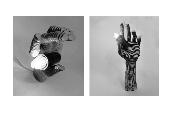
Final Results
Videos
Laser cutting process from Lena Bannaia on Vimeo.
Fabrication files
-
File: MakeHuman avatar ↩↩
-
File: Laser cut sheets ↩