08. WEARABLES
During the workshops with Emma I noticed that good thing is to be prepared with materials as it let's to have more quality workshop. We made the sound and heat drivers and magnetic flip dot coil actuator.
This time I was inspired by the works of these Fabricademy students: Jessica Stanley and Loes Bogers.
![]()
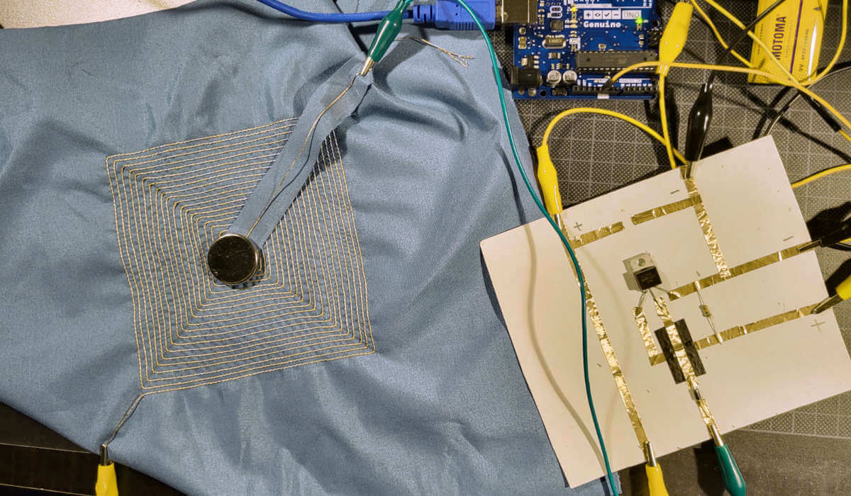
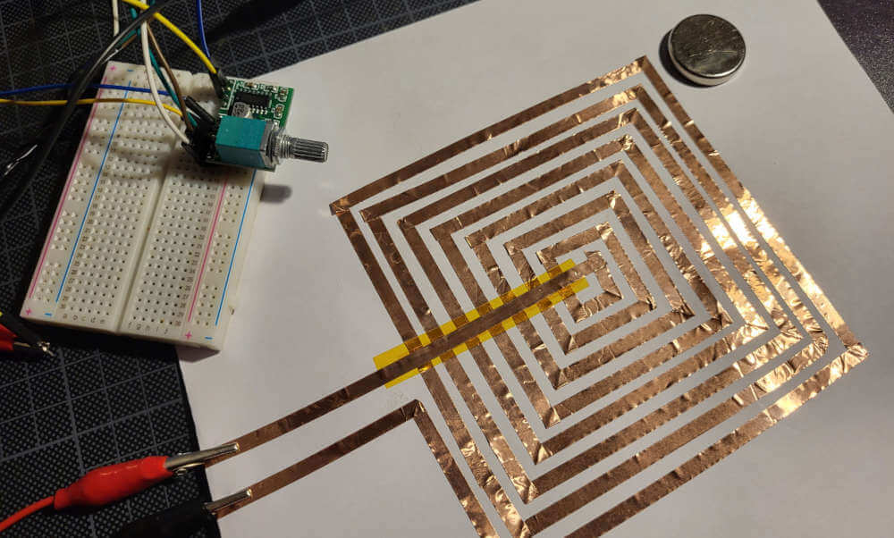
Magnetic flip-dot
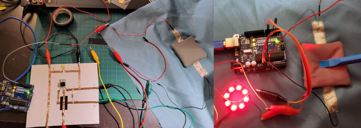
Prototyped coil flip dot during Ema's tutorial class.
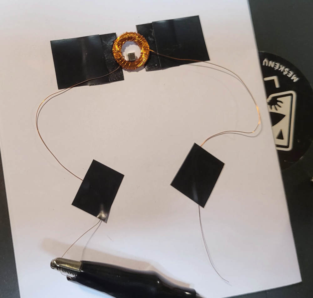
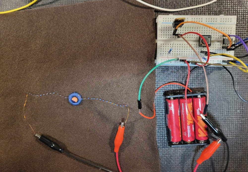
Magnetic flip-dot with ATtiny and swich button.
For the next step Nuria advised that polarity can be controlled with transistors. The ball jumps out because it would have to be threaded through the wire and attached to the coil.
int blinkPin = 0;

void setup()
{
  pinMode(blinkPin, OUTPUT);
}

void loop()
{
  digitalWrite(blinkPin, HIGH);
  delay(500);
  digitalWrite(blinkPin, LOW);
  delay(500);
}
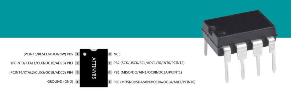
ATtiny 85
Programing with Arduino UNO
materials
- ATtiny85 20PU
- Arduino UNO
- USB cable
- breadboard
- jumper wires M-M
- LED diode 2 pins
- 3V battery and battery holder
Step 1: set Arduino Uno in ISP mode
Connect your Arduino Uno. In Arduino IDE open the ArduinoISP example file (File -> Examples -> ArduinoISP) and upload it.
Step 2: install ATtiny support to Arduino IDE
OPEN: File -> Preferences and in the Additional Boards Manager URLs put this url: https://raw.githubusercontent.com/damellis/attiny/ide-1.6.x-boards-manager/package_damellis_attiny_index.json
Step 3: add support for ATtiny family
OPEN: Tools → Boards → Board Manager...
In white field type “attiny”, install “attiny by David A. Mellis”.
Step 4: connect ATtiny85 with Arduino Uno
- 5V – Vcc
- Gnd – Gnd
- Pin 13 – Pin 2
- Pin 12 – Pin 1
- Pin 11 – Pin 0
- Pin 10 – Reset
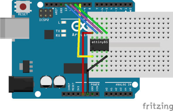
Step 5: add 10uF capacitor
Add a 10uF capacitor between RESET and GND in arduino. This is to avoid arduino from being auto reset when we upload the program to ATtiny85. If you are using a electrolytic capacitor make sure the anode goes in GND of uno.
Step 6: upload program to ATtiny85
In Arduino IDE select these options
1. ATtiny: Tools -> Board
2. ATtiny85: Tools -> Processor
3. Internal 8 MHz: Tools -> Clock
4. Arduino as ISP: Tools -> Programmer
Step 7: Burn Bootloader
By default ATtiny85 runs at 1MHz. To make it to run at 8MHz select Tools -> Burn Bootloader.
Step 8: upload Blink example
1. Open Blink example File -> Examples -> 01.Basics -> Blink
2. Change the pin number from 13 to 0 and upload
Test
Programing with Tiny AVR Programmer
The Tiny AVR Programmer plugs directly into your USB port and provides a programming socket for the ATTiny45 and 85. Tiny AVR Programmer Hookup Guide is easy to start.
materials
- ATtiny85 20PU
- Tiny AVR Programmer
Step 1: install ATtiny support to Arduino IDE
OPEN: File -> Preferences and in the Additional Boards Manager URLs put this url: https://raw.githubusercontent.com/damellis/attiny/ide-1.6.x-boards-manager/package_damellis_attiny_index.json
SOUND
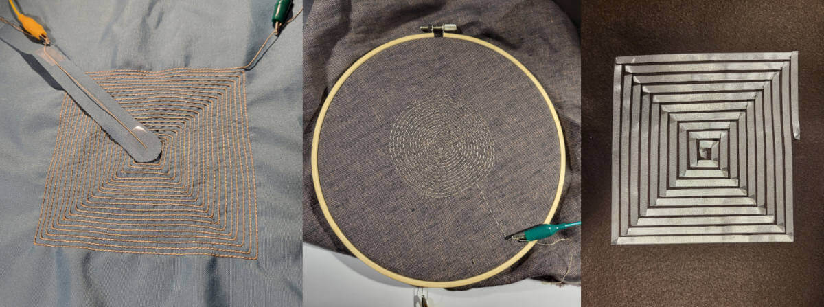
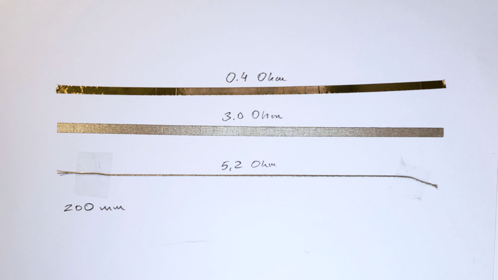
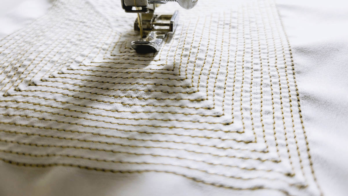
I tried different materials to make the speakers. Shieldex conductive thread on linen sewed by hand and on syntetic fabric with sewing machine. Also textile conductive sticky tape on felt and cooper foil on paper.
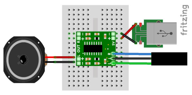
Speaker circuit
For the speakers, I used PAM8403 amplifier. Before that, I tried PAM8403 amplifier with an integrated potentiometer and the sound was better. Bellow is the picture of the circuit.
INSTRUCTIONS how to solder the AUX and USB cables.
materials
- AUX cable (half)
- USB cable (half)
- insulating tape
- solder
- M-M type prototyping wires
tools
- soldering iron
- needle
- cutter
- multimeter
- wire stripper
- permanent marker
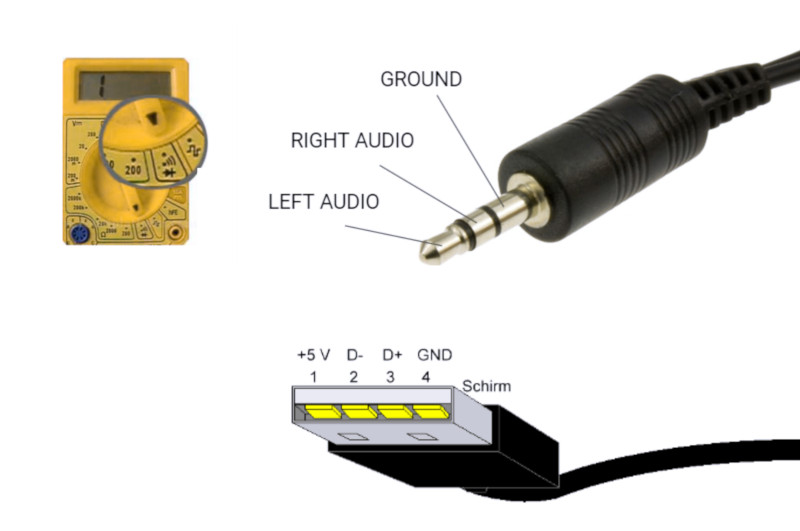
STEP 1 / AUX and USB cables: Cutted both cables in half as only one connector of each is needed.
STEP 2 / AUX and USB cables: Gently removed the top layer of the cable plastic leeving aprox. 4 cm of each wire. Stripped all the wires using wire stripper. If wires very thin it is possible to do that with finger nails. Additionaly I coated the stripped wires with solder to have thicker and stronger wires.
STEP 3 / AUX cable: determined which cable is ground, left and rihgt channels. For this I used the multimeter which was put on the CONTINUITY MODE. The picture bellow shows which part of the AUX cable connector connects the wire. If multimeter is beeping while you touch left audio channel on the connector and blue cable (might be any colour depending on the manufacturer) it indicates that this is left audio channel. So I checked all cables and marked them using insulating tape and permanent marker.
STEP 4 / USB cable: repeated the same process only for two channels - ground and power.
STEP 5 / AUX and USB cables: soldered the M-M type prototyping wires to each connection as I used them on the breadboard. As to connect to sewed amplifier I used the crocodile clip wires.
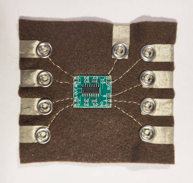
PAM8403 audio amplifier soft circuit
Using beading needle sewed amplifier to the 1.5 mm thickness felt with Shieldex conductive thread and used the metal snap-fasteners and 5 mm sticky conductive fabric tape for the connections.
materials
- PAM8403 audio amplifier
- conductive thread
- sticky conductive fabric tape (5 mm)
- felt (1.5 mm)
- snap-fasteners
tools
- needle
- beading needle
- scissors
- multimeter (to check the connections)
- press for the snap-fasteners
THERMOCHROMIC
I used thermochromic dyed fabrics saved from the workshop at Shemakes project in Discovery path about thermochromic e-textiles and the speakers made during wearables week.