8. Wearables
DIGITAL MEDIA

The potential of digital media in the field of creation have increased. Pathways have been opened for new and open dynamic interactive artworks and a more active audience. Its effects on the world of museums and galleries are highlighted, as well as are incorporating this type of work into their exhibition spaces and into art market.
This week is the second part of the Electronics.
It is getting more and more frustrating that I dont have enough time to explore and dig into each subject deeply as we have such short time and it is always hard to choose and try 1 thing during the week while we see ocean of possibilities, it makes me feel lost.
buuuuut,
let's talk about this week and Arduino's software. I would really love to be a programming professional to create big installations and digital works for being able to make excited experiences with interactions.
INSPIRATION
Joanie Lamercier
![[Espacio fundación Telefónica]](../../images/week8/JoanieLemercier.jpg)
Trying to capture the beauty of nature through digital tools, creating a paranoid experience is what the French artist wants to achieve.
Lull
In the center of an unlit 6,000-square-foot warehouse, waves of liquid light undulate wistfully across the walls of a semitransparent triangular structure. Simple rules shape this ever-evolving animation, giving rise to organic abstracted patterns with complex behavior that teeter between order and chaos
lull from Vincent Houze on Vimeo.
CONDUCTIVE WEEK
OUTPUT - ACTUATORS
Choosing between the following actuators we will create a circuit using hard-soft conections.
VISUAL
-
LEDs
-
Neopixels
-
Optical fibers
-
Thermochromic ink + heated circuit/code
SOUND
- Fabric speakers + amplifier circuits
MOTION
-
Shape memory alloy + high load circuit
-
Flip dot
-
Flapping wing
-
Mini vibration motors
SOUND ACTUATOR
We incorporate a transistor to the circuit that allows us to control the voltage. There are different type of transistors, the one we used was N-Channel, a type of Mosfet. The transistor has three legs: G (gate), D (drain) and S (Source).
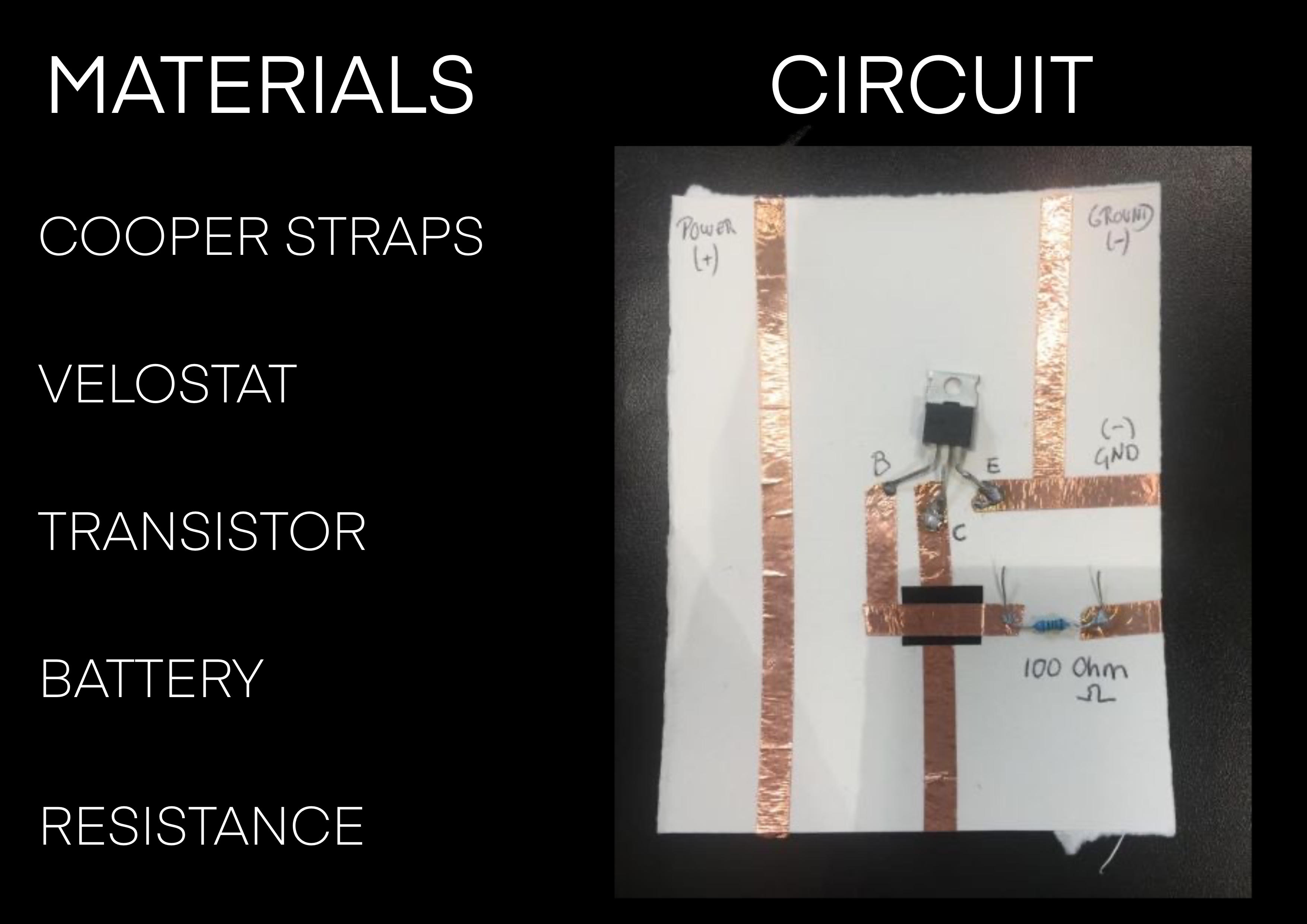
We had trouble to manage the power flowing all over the circuit) As you can see in the video, once we programmed the speaker in Arduino we verified (with the multimeter) that the signal adjusted to the programmed pace in Arduino. When we measured with the multimeter, no current was seen flowing after the resistance.
VISUAL ACTUATOR (LEDS)
Within the visual actuators, we worked with LEDs, NEOPIXELs and with HC-SR04 DISTANCE SENSOR
This sensor provides to 400cm of ultrasonic distance measuring. Each module includes an ultrasonic transmitter/receiver control circuit and it contains 4 pines: Power/Trigger/Receive/Ground
To communicate with the sensor I installed the sensor codification from ARDUINO LIBRARY
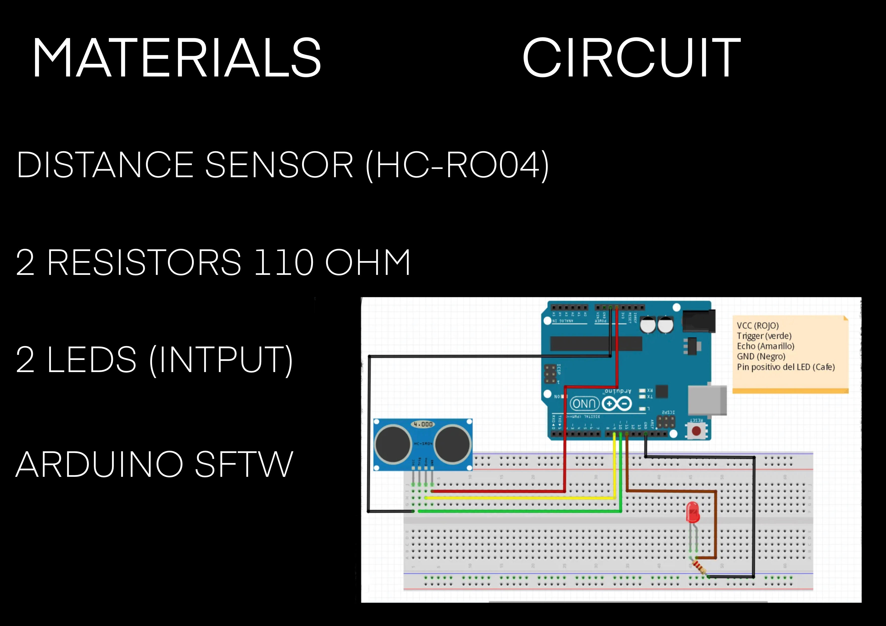
Depending the lecture of the sensor, the intention is to light up one LED or the other.
HOW TO CODIFY ARDUINO
-
I assign Pines to two LEDs
-
I assign Pines to Distance Sensor
-
I identify the pines form the sensor
-
I generate a variable that saves the lecture from the sensor in cm
-
We start the series communication and we define PinMode from the LEDs as an OUTPUT
-
We ascribe the following functioning to the LEDs: we use IF and ELSE to communicate that, if there is a distance superior to 10cm from the sensor, LED1 will turn on and, in consequence, LED2 will turn off
-
We mark a “delay” of 1000 (one thousand), which corresponds to 1 second
Usefun link: ARDUINO LANGUAGE
ARDUINO CODE
int baudrate = 9600;

int triggerPin = 5; // el data Trigger del sensor se aloja en el Pin 5

int echoPin = 6; // el data Echo del sensor se aloja en el Pin 6

int LED1= 12;

int LED2= 7;


float lecsen= 0; // lectura del sensor en esta variable (0)

float maplesen= 0;  // variable del valor del mapeo


SR04 sensor(triggerPin, echoPin);
double cm;


void setup()
{

    Serial.begin(baudrate);

pinMode (TriggerPin, INPUT);

pinMode (EchoPin, INPUT);

pinMode (LED1, OUTPUT);

pinMode (LED2, OUTPUT);


void loop()

{
digitalRead

    cm = sensor.centimeters();

    Serial.print("cm: ");

    Serial.println(cm);

    delay(1000);
}
VISUAL ACTUATOR (NEOPIXEL)
In this case we change LEDs for 30 neopixels.
Like we did on the last exercise, chek in Arduino Library to create the code. We will use Adafruit Neopixel
Interacting with the Distance Sensor we want to achieve the following reaction:
When stimulating the sensor with a distance inferior to 10cm , the Neopixels will turn on one by one JUST if there is a previous sensor stimulation. Without stimulating the sensor, the light will not go on.
The materials are the same as the last one, but we got neopixels insted of Leds
HOW TO CODIFY ARDUINO
-
Include the Distance Sensor library (HC-SR04) and Adafruit_Neopixel
-
Connect Pin 10 with the Neopixel
-
Define the number of Neopixels to 30
-
Generate a variable that holds the number of pixels
-
Generate variables for each rgb value
-
DELAY 0.5sec as pause time between pixels
-
PIXELS.CLEAR(); Set all pixel colors to 'off'
-
Start serial communication
-
We give value to the RGB variables (Random), from 0,0,0 to 255,255,255
-
The Neopixel wiring, one goes to Ground and the other to the signal
-
It is powered by an external power supply (5v)
ARDUINO CODE
//Incluyo liubrería de sensor de proximidad.
#include <NHCSR04.h>


#include <Adafruit_NeoPixel.h>
#ifdef __AVR__
 #include <avr/power.h> // Required for 16 MHz Adafruit Trinket
#endif

// Which pin on the Arduino is connected to the NeoPixels?
#define PIN        10 // On Trinket or Gemma, suggest changing this to 1

// How many NeoPixels are attached to the Arduino?
#define NUMPIXELS 30 // Popular NeoPixel ring size

// When setting up the NeoPixel library, we tell it how many pixels,
// and which pin to use to send signals. Note that for older NeoPixel
// strips you might need to change the third parameter -- see the
// strandtest example for more information on possible values.
Adafruit_NeoPixel pixels(NUMPIXELS, PIN, NEO_GRB + NEO_KHZ800);

#define DELAYVAL 500 // Time (in milliseconds) to pause between pixels

//Genero variable para el valor de comunicación serie.
int baudrate = 9600;


// Asigno pines a Proximity sensors
int triggerPin = 5;
int echoPin = 6;

//referencio los pines del sensor
SR04 sensor(triggerPin, echoPin);

//Genero una variable que aloje la lectura del sensor en cm.
double cm;

// Genero una variable que aloja el numero de pixeles
int numPixel = 0;
// Genero variables para cada valor de rgb
int r = 50;
int g = 57;
int b = 70;

void setup()
{
  //Iniciamos comunicación serie
    Serial.begin(baudrate);
//Definimos pinmode de LEDs como Output


 // These lines are specifically to support the Adafruit Trinket 5V 16 MHz.
  // Any other board, you can remove this part (but no harm leaving it):
#if defined(__AVR_ATtiny85__) && (F_CPU == 16000000)
  clock_prescale_set(clock_div_1);
#endif
  // END of Trinket-specific code.

  pixels.begin(); // INITIALIZE NeoPixel strip object (REQUIRED)
// Set all pixel colors to 'off'
 pixels.clear();
}

void loop()
{
  //HAcemos lectura del sensor en cm.
    cm = sensor.centimeters();


// si hay un estimulo <10 se genera este estímulo
if (cm<10){


  numPixel ++;
   r= random (155,255);
   g= random (175,255);
   b= random (100,255);

    // pixels.Color() takes RGB values, from 0,0,0 up to 255,255,255
    // Here we're using a moderately bright green color:
    pixels.setPixelColor(numPixel, pixels.Color(r, g, b));

    pixels.show();   // Send the updated pixel colors to the hardware.

    delay(DELAYVAL); // Pause before next pass through loop
 if(numPixel ==30){
numPixel=0;
pixels.clear();}

  if(r >=255){r=10;}
  if(g >=255){g=75;}
   if(b>=255){b=0;}
}
  }
I show you the result
My intention is to continue exploring with Arduino and try to test different possibilities of creating circuits. With a lot of work I hope to be able to integrate programming into my final project.