13. Skin Electronics
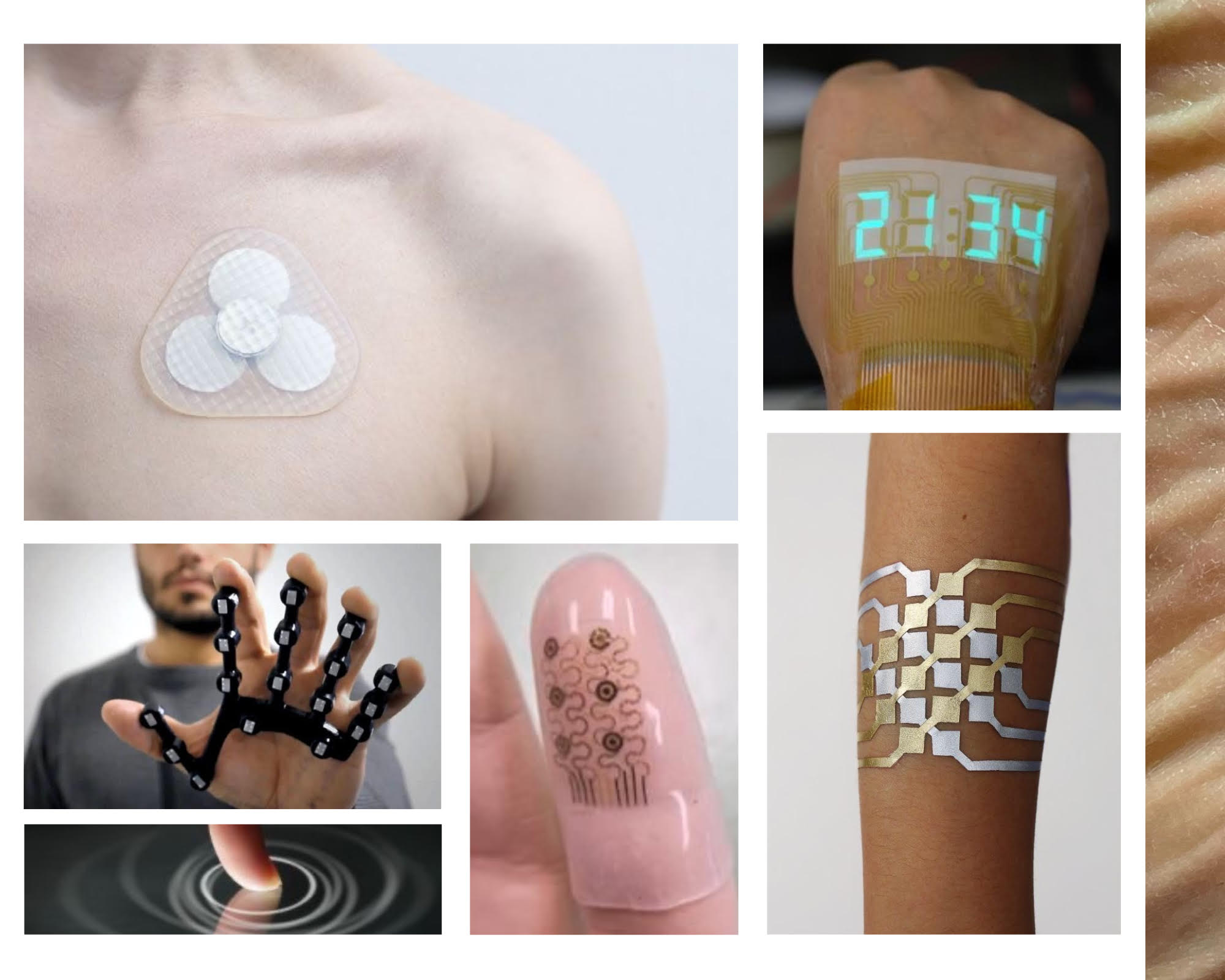
A SECOND SKIN
The skin envelops us. It is a mirror of many invisible emotions that live within us. It is the most sincere way to talk about ourselves, revealing our way of being and existing in this world
INSPIRATION
 made by canvas
Tuvie/ Padraig Belton / DuoSkin / Hal Hodson
Weekly inspo Folder
This week Katia Vega has given us a very interesting and fun tutorial warning us of the present and future partnerships between technology and skin professionals, such as makeup artists, prosthetic experts and tattoo artists, to embrace the idea of human-device symbiosis. FX e-makeup made use of special effects makeup to hide electronic components that detect facial muscle movements, acting like a second skin.
KINISI by Katia Vega
PROCESS AND WORKFLOW
We start the week practicing different arduino codes and different microcontrollers. Next I show how I have worked with the Matrix code and the steps to follow to make the analog sensor.
ANALOG SENSOR
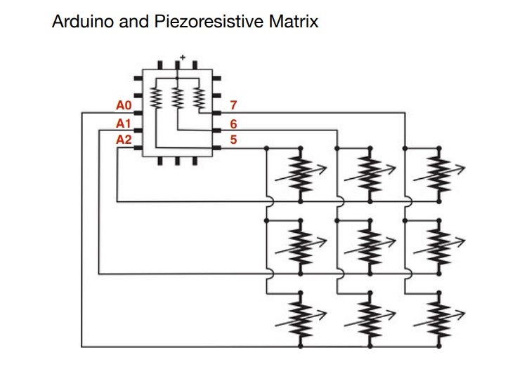
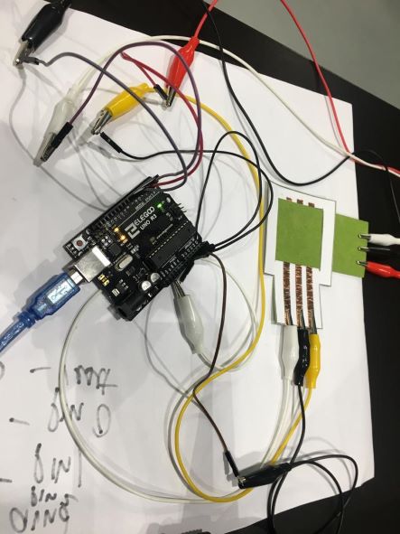
These are the steps we have followed to make the analog sensor link
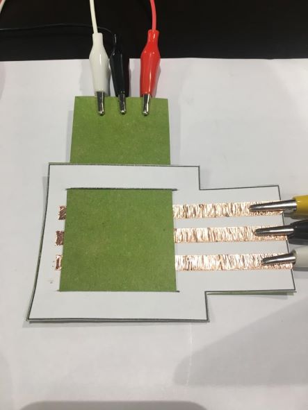
Matetrials:
-
paper
-
velostat
-
copper tape
And here Emma's Code
//Emma Pareschi- Dec 2020
//Modify example from Pressure Sensor Matrix Code
//parsing through a pressure sensor matrix grid by switching individual
//rows/columns to be HIGH, LOW or INPUT (high impedance) to detect
//location and pressure.
//>> https://www.kobakant.at/DIY/?p=7443

#define numRows 5
#define numCols 5
#define sensorPoints numRows*numCols

int rows[] = {A0, A1, A2};
int cols[] = {5,6,7};
int incomingValues[sensorPoints] = {};

void setup() {
// set all rows and columns to INPUT (high impedance):
for (int i = 0; i < numRows; i++) {
  pinMode(rows[i], INPUT_PULLUP);
}
for (int i = 0; i < numCols; i++) {
  pinMode(cols[i], INPUT);
}
  Serial.begin(9600);
}

void loop() {

for (int colCount = 0; colCount < numCols; colCount++) {
  pinMode(cols[colCount], OUTPUT); // set as OUTPUT
  digitalWrite(cols[colCount], LOW); // set LOW

  for (int rowCount = 0; rowCount < numRows; rowCount++) {
  incomingValues[colCount * numRows + rowCount] = analogRead(rows[rowCount]); // read INPUT
}// end rowCount

pinMode(cols[colCount], INPUT); // set back to INPUT!

}// end colCount

// Print the incoming values of the grid:
for (int i = 0; i < sensorPoints; i++) {

  Serial.print(incomingValues[i]);
  if (i < (sensorPoints-1)) {
    Serial.print("\t");}
//    Serial.println("");}
  }


Serial.println();
delay(10);
}
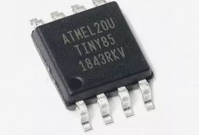
ATTINY
It is a small board with the ATTINY85 microcontroller chip that can function similar to an Arduino nano. It can be programmed with the Arduino IDE. One of the problems with this chip is that it only has 6 kB for our Sketch, so we can only make small programs.
We have not been able to work with attiny but below I show the steps to follow to install and configure with the computer
-
Up to 6 I/O pins available
-
8 kB flash program memory (2 kB is used by the system for the bootloader, so we have 6 kB left)
-
10-bit ADC, 4 channels (or 2 differential channels) and temperature measurement.
-
8-bit timer/counter, high speed and separate prescaler
-
Analog comparator.
-
Multiple sources of interruption
-
Configurable internal clock oscillator
1) We are going to make a blink the LED that the board has integrated.
2) First we are going to install the drivers so that our Windows recognizes it. Digistump.Drivers.zip
3)Now we are going to configure the IDE so that it recognizes the Digispark Tiny85 card, for this we click on Tools / Board: / Card manager...
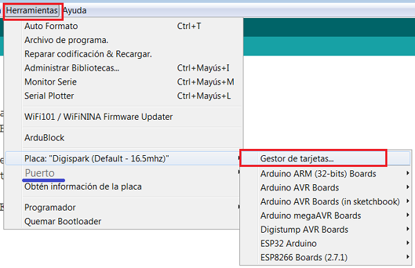
4)We go back to Tools / Board / and assign the Digispark (Default - 16.5mhz)
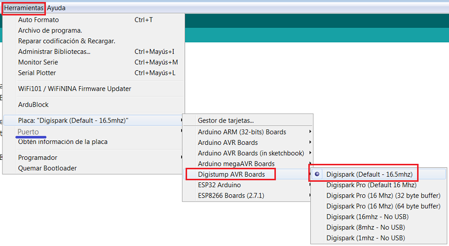
5)We already have our IDE ready to work with this card.
6) Let's load the Example Start
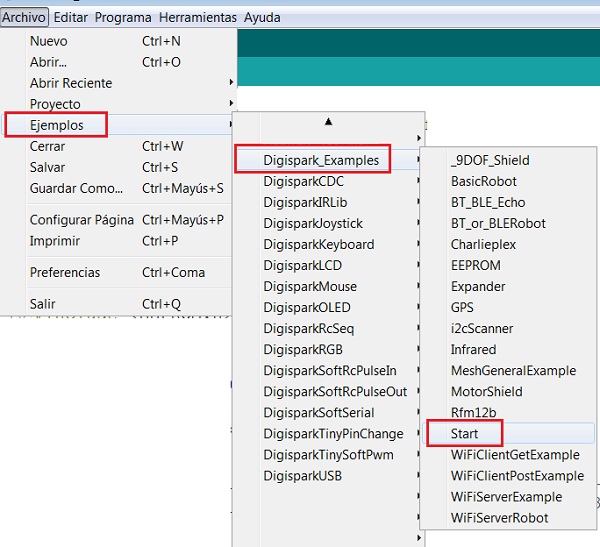
7)In this module the internal LED is connected to the P1 terminal of the module. It's terminal 6 of the chip.
8) Copy the code
// the setup routine runs once when you press reset:
void setup() {
  // initialize the digital pin as an output.
  pinMode(0, OUTPUT); //LED on Model B
  pinMode(1, OUTPUT); //LED on Model A  or Pro
}

// the loop routine runs over and over again forever:
void loop() {
  digitalWrite(0, HIGH);   // turn the LED on (HIGH is the voltage level)
  digitalWrite(1, HIGH);
  delay(1000);               // wait for a second
  digitalWrite(0, LOW);    // turn the LED off by making the voltage LOW
  digitalWrite(1, LOW);
  delay(1000);               // wait for a second
}
FINAL RESULT
I can feel the fatigue of the last week. We have been 13 days non-stop exploring and learning new things. Although this experience is being one of the best, I must also be honest: the nerves have taken out pimples and my back is like a crooked snail!!
Thats why Ziortza and I we decide to create something to improve our posture with electronics. Counting on the tools we have, we opted for the playground board which has many possibilities to work, its advantages are that it has introduced different actuators like an accelerometer. temperature sensor, motion, speaker and lighting.
STEP BY STEP
-
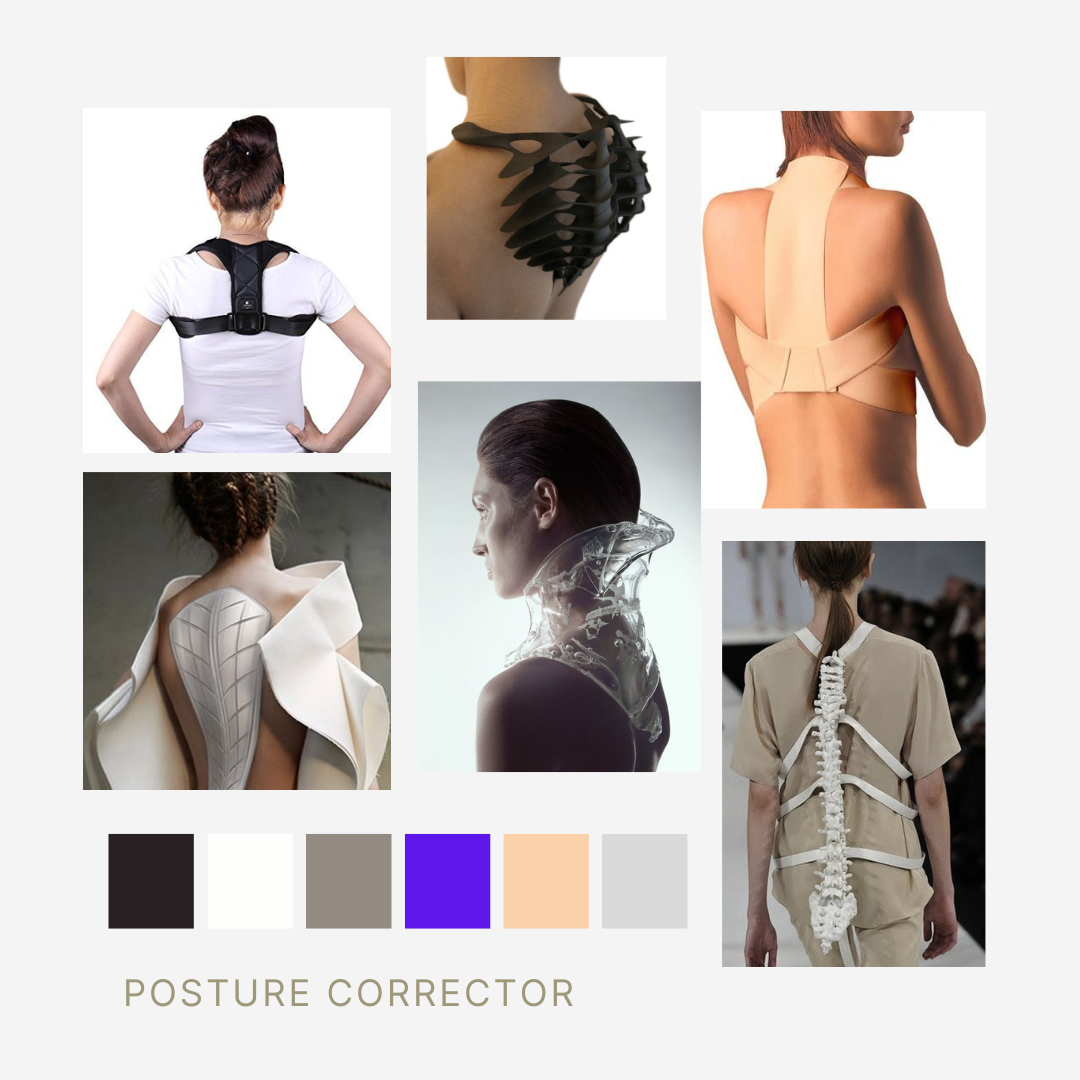
First of all it is important to define the pryect and search on internet for ideas that already exist
-
The posture correctors that I have found on the internet are a kind of mesh that what it does is make you pressure between the shoulder blades and so you can be more aware of your posture, but is it really feasible? In my case I wanted to give a chance but I did not see that it solved the problem.
-
Taking advantage of this week of electronics I wanted to improve this idea and introduce alarms to alert an incorrect posture
-
As I see at last weeks, is very important how you search de questions on internet to resolve dubs with electronics, so the first thing was to know our controler and how it works.
1)We will use the accelerometer on the Circuit Playground to measure the slouch angle.
 video taken by Adafruit Circuit Playground
Check here to see all the caracteristics of this microcontroler Adafruit Circuit Playground
Some of the Internally Used Pins:
-
D4 - Left Button A
-
D5 - Right Button B
-
D7 - Slide Switch
-
D8 - Built-in 10 NeoPixels
-
D13 - Red LED
-
D27 - Accelerometer interrupt
-
D25 - IR Transmitter
-
D26 - IR Receiver
-
A0 - Speaker analog output
-
A8 - Light Sensor
-
A9 - Temperature Sensor
-
A10 - IR Proximity Sensor
We use the Data Flow wire to program to the computer
2) I use the next code for Slouch Detector Angle Demo to see how it works
// Circuit Playground Slouch Detector Angle Demo
//
// Compute current angle using accelerometer.
// Compare asin() to atan2().
//
// Author: Carter Nelson
// MIT License (https://opensource.org/licenses/MIT)

#include <Adafruit_CircuitPlayground.h>

#define GRAVITY             9.80665   // standard gravity (m/s^s)
#define RAD2DEG             52.29578  // convert radians to degrees

float currentAngle1;
float currentAngle2;

///////////////////////////////////////////////////////////////////////////////
void setup() {
  Serial.begin(9600);

  // Initialize Circuit Playground
  CircuitPlayground.begin();
}

///////////////////////////////////////////////////////////////////////////////
void loop() {
  // Compute current angle
  currentAngle1 = RAD2DEG * asin(-CircuitPlayground.motionZ() / GRAVITY);
  currentAngle2 = RAD2DEG * atan2(-CircuitPlayground.motionZ() ,
                                   CircuitPlayground.motionX() );

  // Print current angle
  Serial.println(currentAngle1);
  Serial.print(",");
  Serial.println(currentAngle2);

  // But not too fast
  delay(100);
}
3) Then open the serial plotter: Tools -> Serial Plotter
4) If the current angle sensed by the Circuit Playground (currentAngle) exceeds a preset value (SLOUCH_ANGLE), then we are slouching and should sound an alarm
// Circuit Playground Slouch Detector Angle Demo
//
// Compute current angle using accelerometer.
// Compare asin() to atan2().
//
// Author: Carter Nelson
// MIT License (https://opensource.org/licenses/MIT)

#include <Adafruit_CircuitPlayground.h>

#define SLOUCH_ANGLEMAX       10
#define SLOUCH_ANGLEMIN       -30
#define GRAVITY             9.80665   // standard gravity (m/s^s)
#define RAD2DEG             52.29578  // convert radians to degrees

int currentAngle;

//int currentAngle1;
//int currentAngle2;

///////////////////////////////////////////////////////////////////////////////
void setup() {
  Serial.begin(9600);

  // Initialize Circuit Playground
  CircuitPlayground.begin();
}

///////////////////////////////////////////////////////////////////////////////
void loop() {
  // Compute current angle
  //currentAngle1 = RAD2DEG * asin(-CircuitPlayground.motionZ() / GRAVITY);
  //currentAngle2 = RAD2DEG * atan2(-CircuitPlayground.motionZ() ,


  // Compute current angle
  currentAngle = RAD2DEG * asin(-CircuitPlayground.motionZ() / GRAVITY);

 // Check if slouching
  if (currentAngle > SLOUCH_ANGLEMAX || currentAngle <SLOUCH_ANGLEMIN ) {
    // Sound alarm
    CircuitPlayground.playTone(800, 500);
  }


  // Print current angle
  Serial.println(currentAngle);


  // real movement
  delay(50);
}
5) With the previous sketch loaded and running in the Circuit Playground, you should hear the alarm sound if the tilt angle (hunched over) is greater than 10 degrees.
6) Next step is to introduce a red light to alert the curvature. For that I start programing a small Red LED in the protoboard to see if the code works.
7) Include NeoPixel.h librari
#include <Adafruit_NeoPixel.h>
#ifdef __AVR__
 #include <avr/power.h> // Required for 16 MHz Adafruit Trinket
#endif

//


//Seccion de declaracion de parametros fijos.
#define ALARM 10
#define NUMPIXELS 1 //
Adafruit_NeoPixel pixels(NUMPIXELS, ALARM, NEO_GRB + NEO_KHZ800);
// Declaracion de variableds
POSTURE CORRECTOR
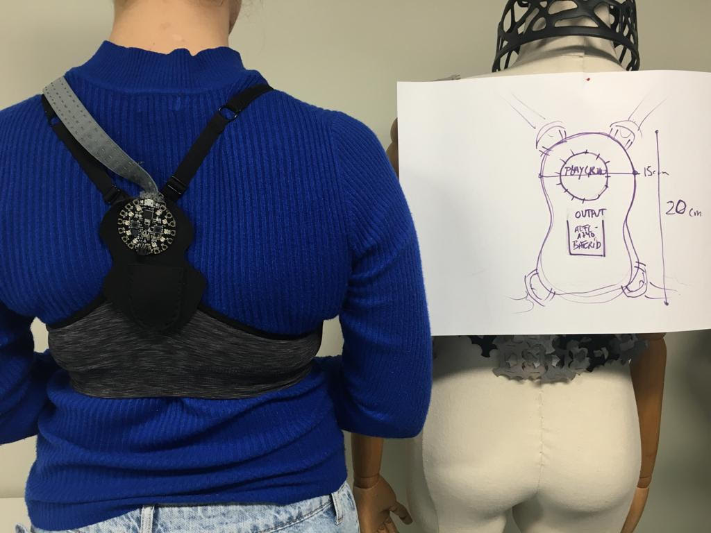
MATERIAL TABLE
| TOP | NEOPRENE | ELASTIC TAPE AND CONDUCTIVE THREADS | BED TEMPERATURE | SPEED RETRACTION | RETRACTON DISTANCE |
|---|---|---|---|---|---|
| Reuse a sports top so that it is well attached to the body and mobility is real | Neoprene fabric for sewing electronics components | The conductive threads are sewn into the elastic fabric so that movement does not break them. The three threads run to the small neopixel on the chest | 40mm/seg | 35mm/seg | 0,8mm/seg |
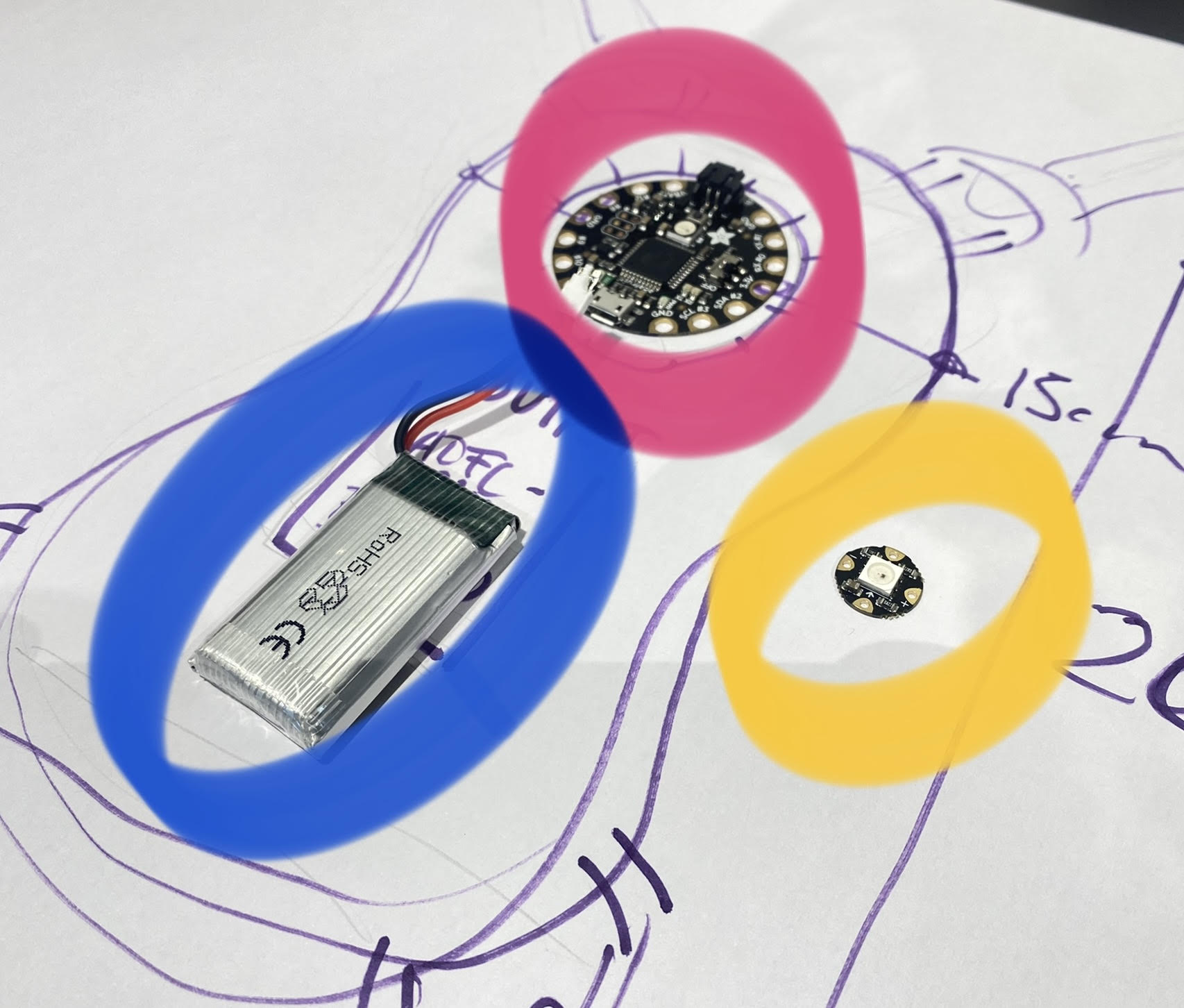
BLUE +3.7 V BATTERY
YELLOW FLORA NEOPIXEL V2
PINK ADAFRUIT PLAYGROUND