6. Computational Couture

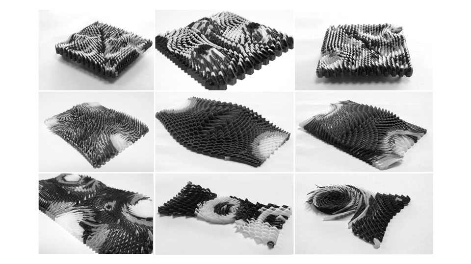
Figure 1: Different samples of 3D print / Caress of Gaze
Research & Ideation
Behnaz Farahi's work blends architecture, interaction design, and fashion, as demonstrated in her 3D-printed garment Caress of the Gaze. This innovative piece is designed to respond to the wearer's environment through a fascinating interactive feature. The garment incorporates sensors that detect when someone is staring at the wearer. Upon detecting this gaze, the garment reacts by moving in response, creating an interactive, dynamic experience. The piece explores themes of privacy, attention, and personal space, reflecting Farahi's interest in how technology can engage with the human body and social interactions. By using 3D printing, Farahi is able to create complex, responsive designs that push the boundaries of both fashion and interaction design, offering a new way to think about garments as more than just static objects but as responsive, living parts of a person's experience.
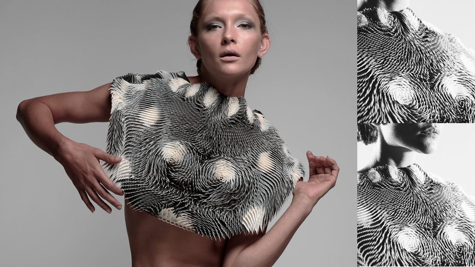
Figure 2: Behnaz Farahi / Caress of Gaze retrieved from Behnaz Farahi
References & Inspiration
Ganit Goldstein's work focuses on creating personalized and sustainable garments by combining 3D printing and embroidery. Her process involves using a 360-degree body scanner to obtain an accurate representation of the body, allowing the garments to be fully custom-made. She utilizes multicolor 3D printing to produce intricate and detailed pieces, merging advanced technologies with traditional techniques like embroidery. Her collection "WeAreAble" is an innovative proposal that challenges fast fashion by focusing on creating zero-waste clothing using recycled materials, promoting sustainability in the fashion industry. Additionally, her work is influenced by traditional weaving techniques, such as ikat, integrating them into her futuristic designs.
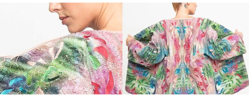
Figure 3: Goldstein / WeareAble retrieved from Ganit Goldtein
Anouk Wipprecht's work integrates technology and fashion in a groundbreaking way, as demonstrated in her 3D-printed fashion collection for Audi. The collection features garments embedded with advanced technological elements, such as parking sensors and headlights. These sensors allow the garments to respond to the wearer's environment, providing interactive and functional designs. For example, the pieces can light up or react when the wearer is near an object or person, mimicking the way cars' parking sensors and headlights function. This innovative fusion of fashion and technology explores the future of wearable tech, highlighting how 3D printing can be used to create not only visually striking but also interactive and functional fashion pieces. The collection emphasizes the potential for technology to enhance personal expression and provide new functionalities within the realm of design.
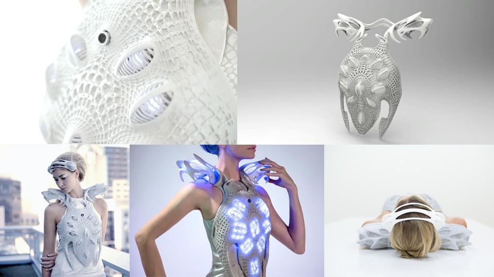
Figure 4: Wipprecht / Synapse Dress retrieved from Anouk Wipprecht

Figure 5: Wipprecht / Spider retrieved from Anouk Wipprecht
References
Tools
Process and Workflow
Parametric bracelet. Modeling and Surface Patterning in Rhino
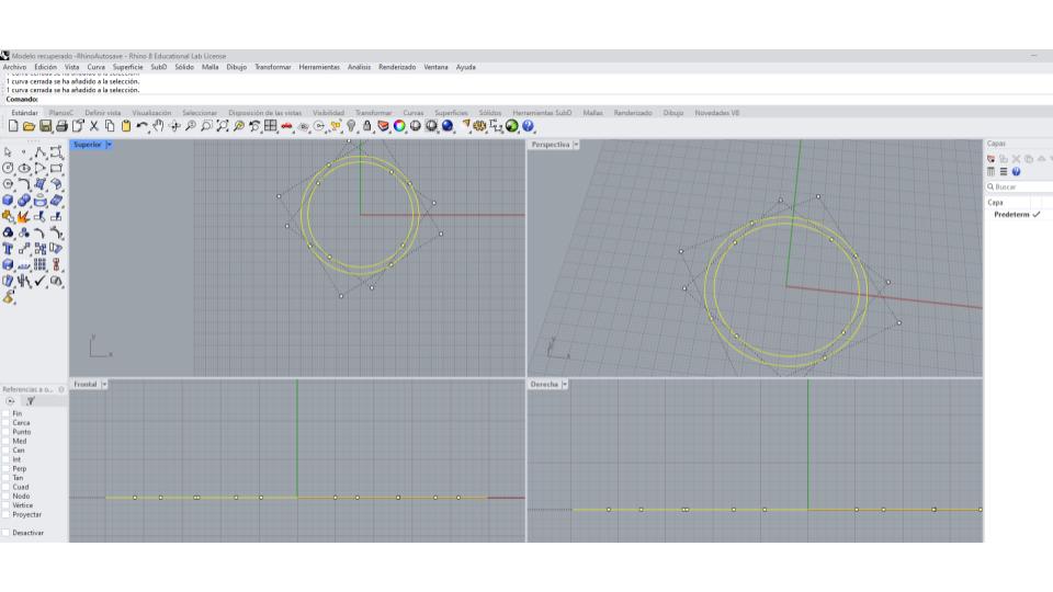
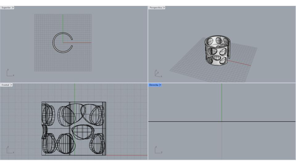
I began by creating the base geometry of the bracelet using the Circle tool. First, I drew a circle and then created a second concentric circle with a larger diameter to obtain a uniform wall thickness of approximately 4 mm. Once this initial profile was defined, I used the Line tool to draw two lines at an angle of about 15 degrees, which would later be used to create an opening in the ring.
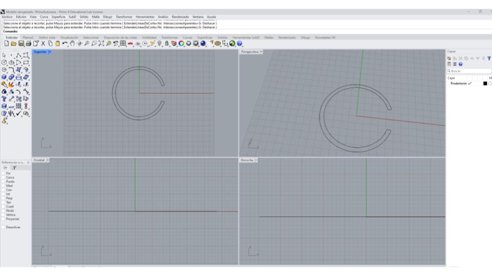
 Using these lines as references, I applied the Trim tool to cut the circular geometry. After removing the unnecessary construction lines, I obtained a shape similar to the letter "C." To ensure the geometry was continuous, I used the Join command to connect the remaining segments into a single closed curve.
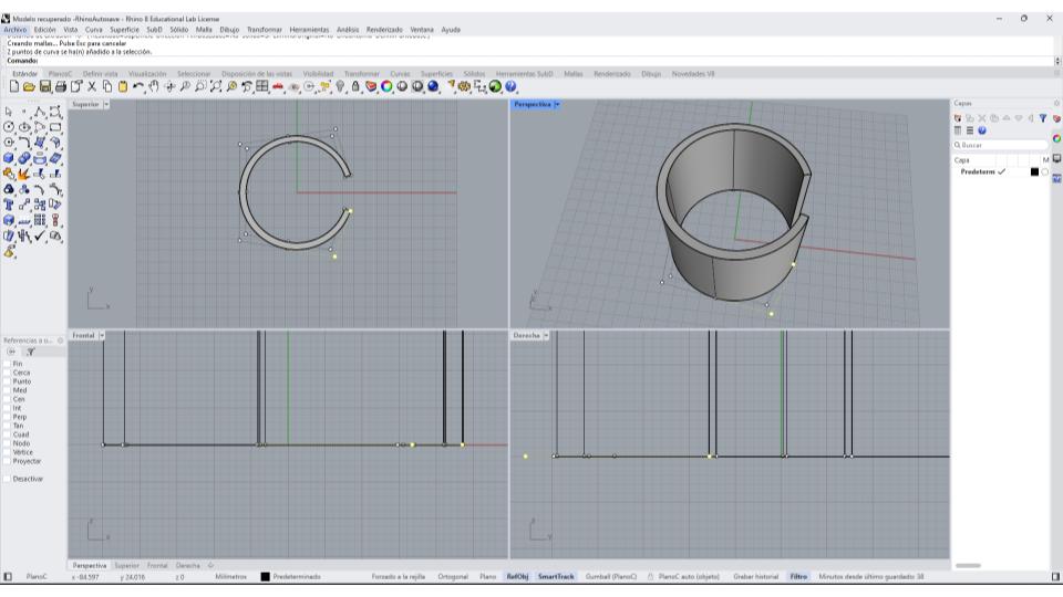
 Once the base shape was complete, I transformed it into a three-dimensional object using the Extrude Curve tool. I set the extrusion height to 40 mm, creating an open cylindrical form that would serve as the foundation for the patterned design.
 The next step was preparing the surface for the perforation pattern. To do this, I used the CreateUVCrv command, which generates a flat representation of a curved surface. This operation unrolled the cylindrical surface into a two-dimensional plane, allowing me to work on the pattern more accurately and efficiently.
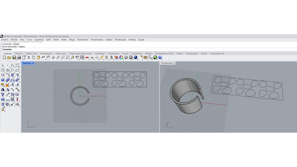 On this flattened surface, I began designing the perforation pattern. I primarily used the Circle and Line tools to create the elements that would form the openings. As the design evolved, I copied, aligned, and distributed the circles to create a balanced and repetitive composition. I carefully adjusted the spacing between the elements to ensure they remained within the boundaries of the surface and maintained a consistent visual rhythm.
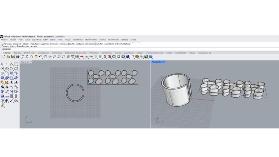 Once I was satisfied with the pattern, I converted the two-dimensional elements into solid volumes using Extrude Curve. These shapes were extruded with enough thickness to pass completely through the main body, extending approximately 4 mm above and 4 mm below the working surface.
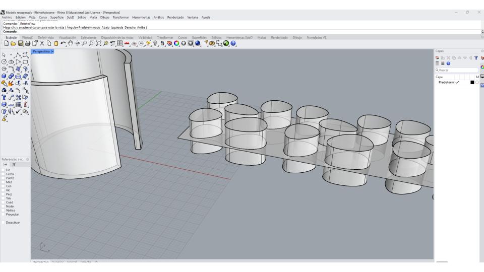 With the pattern volumes completed, I used the FlowAlongSrf (Flow Along Surface) command. I first selected the flattened UV surface as the base surface and then selected the curved ring surface as the target surface. This operation automatically mapped the entire pattern onto the cylindrical geometry while preserving its proportions and arrangement.
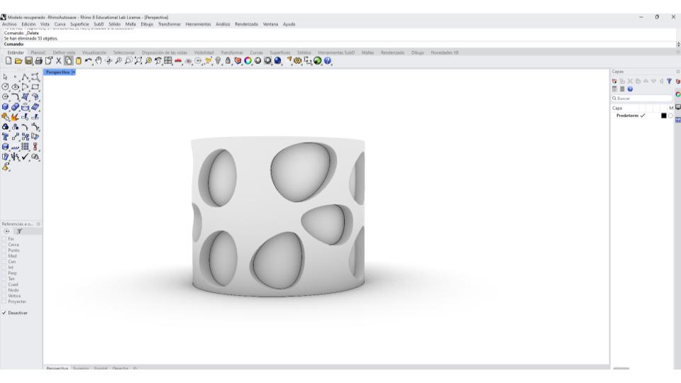
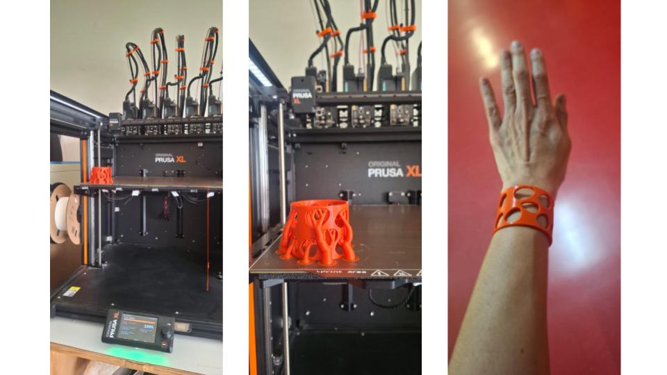
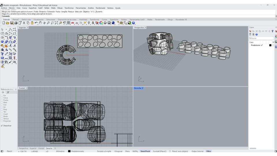 Finally, I used the Boolean operation to create the actual perforations. I selected the main ring body and then the extruded pattern volumes as the cutting objects. Rhino subtracted these volumes from the ring, producing a series of openings distributed across the surface. The result was a three-dimensional ring featuring a customized perforated pattern integrated into its geometry, ready for digital fabrication and 3D printing.
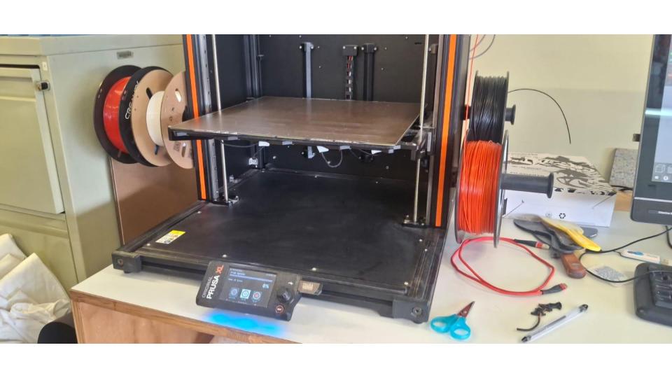
 To manufacture a part using a Prusa 3D printer, I first open the STL file in PrusaSlicer and verify that the dimensions are correct. Then, I check the orientation of the model to reduce the need for supports and improve print quality.
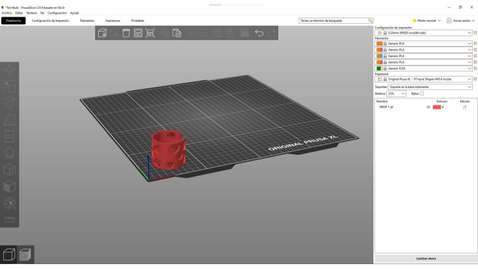 Once the model is properly positioned on the virtual build plate, I select the printer profile, material, and printing parameters, such as layer height and infill percentage. I also evaluate whether the part requires supports and adjust the settings according to its geometry.
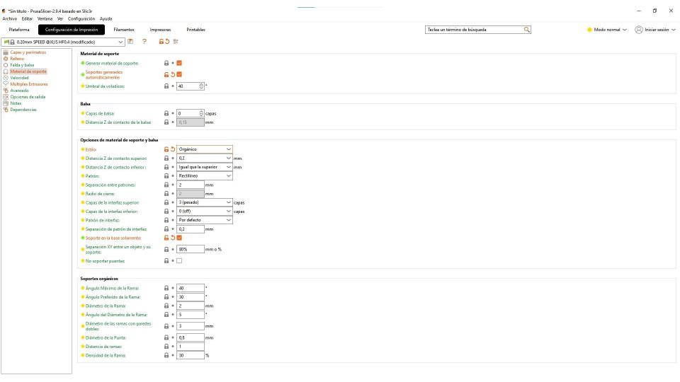 After the setup is complete, I use the Slice Now function, which converts the 3D model into layers and generates the toolpaths that the printer will follow. Before proceeding, I review the layer-by-layer preview to make sure there are no errors or potential printing issues.
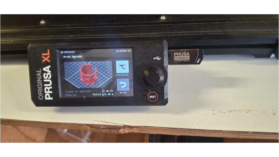
 Finally, I export the file as G-code, which contains all the instructions needed by the printer, including movements, temperatures, and printing speeds. I transfer the G-code to the printer, check that the print bed and filament are ready, and start the printing process. During the first few minutes, I carefully monitor the first layer, since proper adhesion is essential for a successful print. Once the print is finished, I remove the part, clean any supports if necessary, and evaluate the final result.
Adapting a Cults3D Pattern for Textile Fabrication
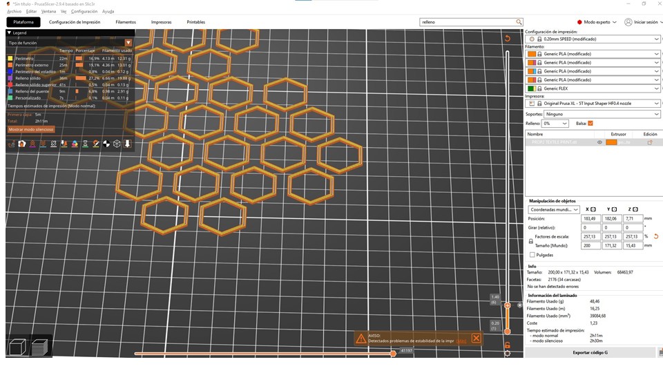
For this exercise, I downloaded a fabric-printing pattern from Cults3d, a platform where both free and paid designs created by different designers can be found. Specifically, I used a pattern designed by Milan Gajic.

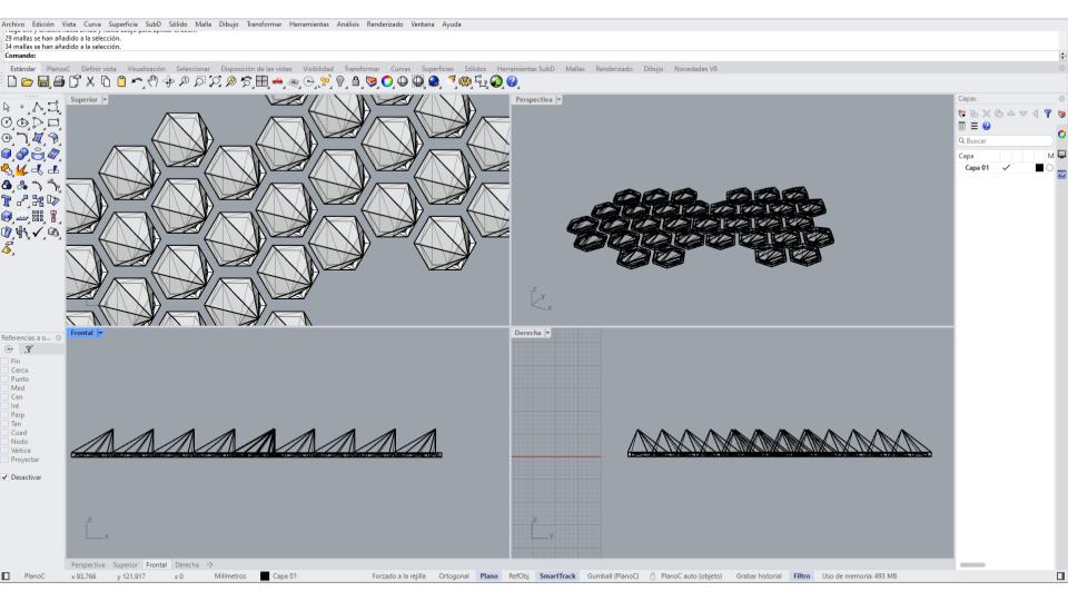
After downloading the file, I imported it into Rhino to prepare it for fabrication. To increase the printable surface area and produce a larger textile sample, I duplicated the original pattern and arranged the copies across the workspace. This modification allowed me to maximize the available printing area and create a larger fabric structure for subsequent fabrication tests.
I opened the file in Ultimaker Cura to prepare it for printing. After inspecting the model, I noticed that it was too small for the intended application, so I decided to scale it to 40%. Once the size was adjusted, I removed the brim and proceeded with the slicing process.
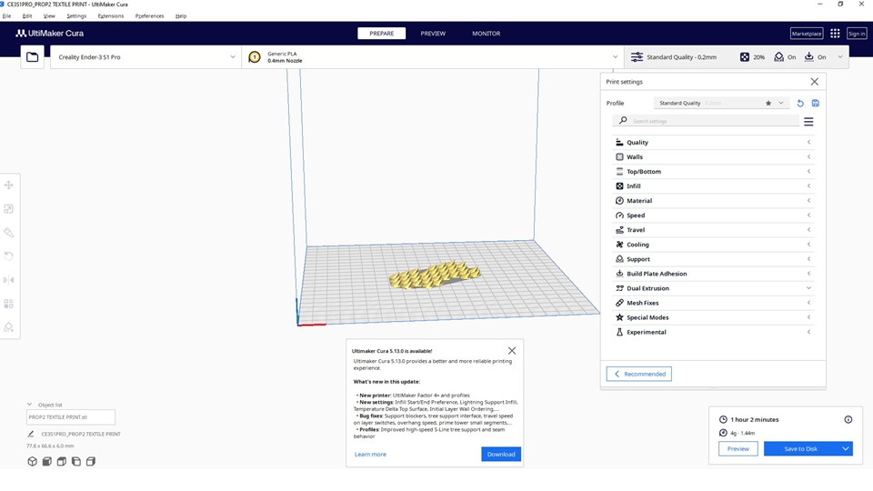
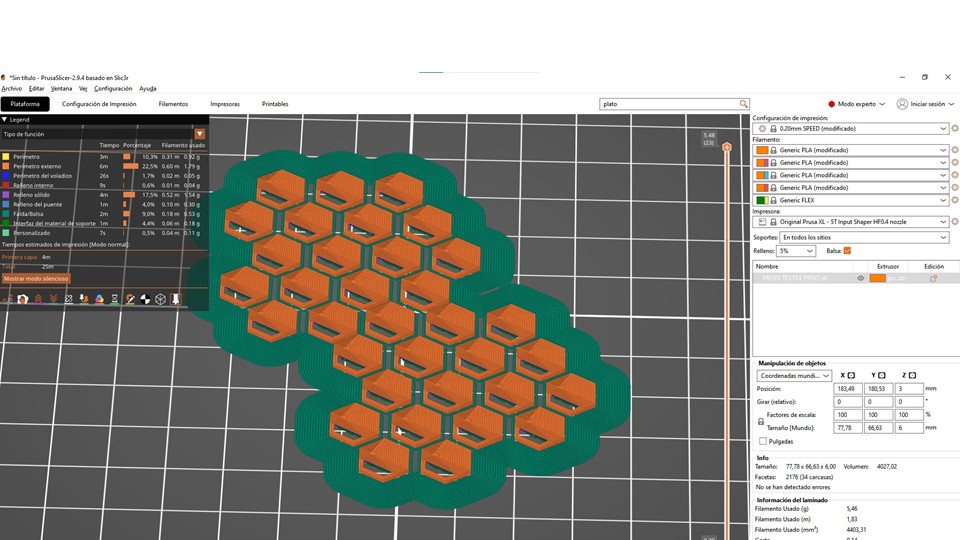
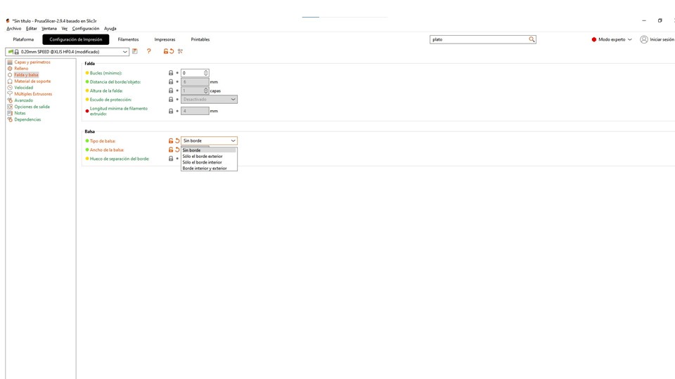
 During the slicing setup, I set the layer height to 0.24 mm, balancing print quality and printing time. I then carefully reviewed the first layer to ensure proper bed adhesion and to verify that the toolpaths were correct.
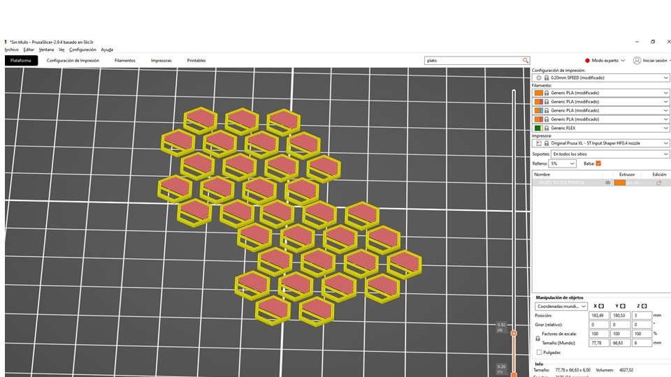
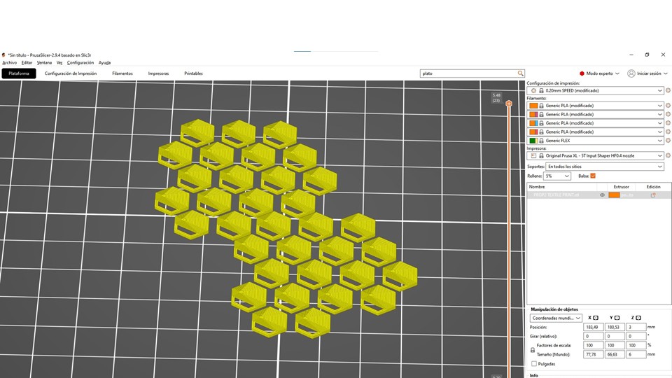
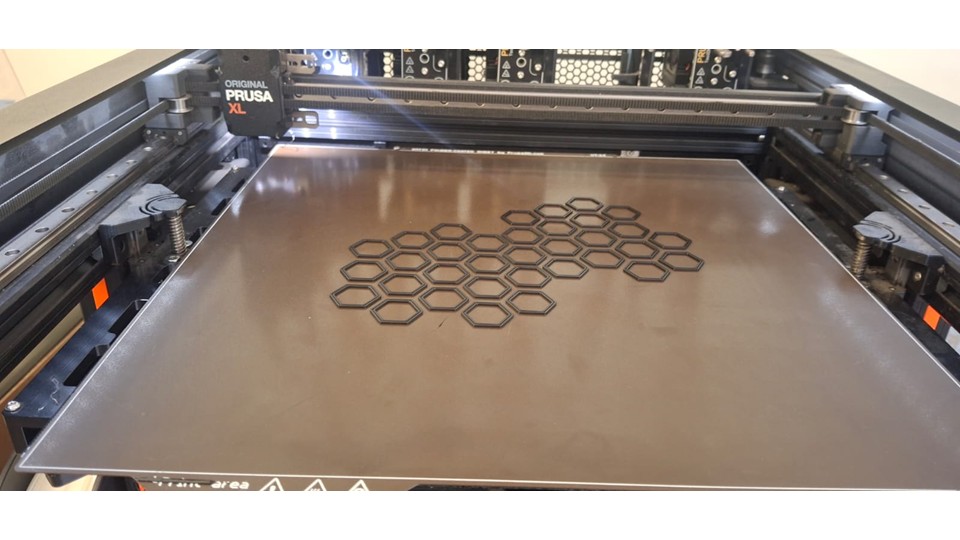
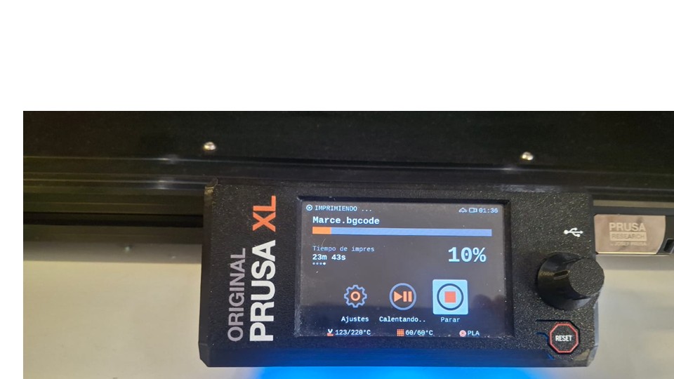
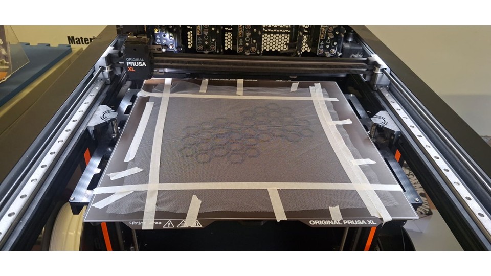
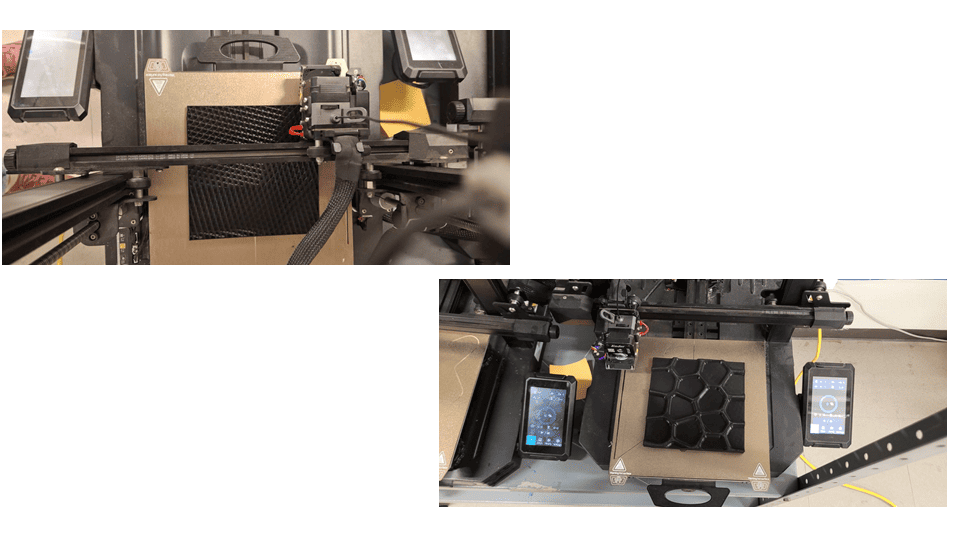
As part of the experimental process, I programmed a pause at 1 minute and 40 seconds into the print. When the printer reached that point, I manually placed the fabric onto the printed surface, making sure it was properly aligned and free of wrinkles. After positioning the fabric, I resumed the print, and the printing process continued normally, allowing the subsequent layers to embed and secure the textile material within the printed structure.
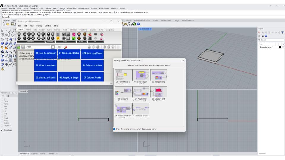
Creating a Voronoi Model in Rhino
When I started creating a Voronoi pattern in Rhino, my objective was not only to generate an organic visual texture but also to develop a geometry that could later be fabricated through 3D printing. For that reason, I worked in Grasshopper, where I could control the parameters and quickly modify the design according to fabrication requirements.
The first step was to create a rectangular surface in Rhino that would define the working area of the pattern. Once the surface was ready, I opened Grasshopper and referenced this surface using the Surface component. This surface acted as the boundary where all the Voronoi cells would be generated.
 Next, I needed points to define the Voronoi structure. To do this, I used the Populate Geometry component and connected the rectangular surface to it. By adjusting the number slider, I could control how many points were distributed across the surface. Increasing the number of points produced a denser and more complex pattern, while reducing the number created larger and more open cells.
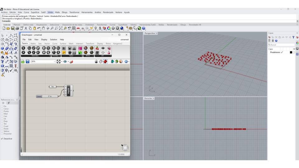
After generating the points, I connected them to the Voronoi 2D component. Grasshopper automatically calculated the regions of influence around each point, generating a network of cells where every area was defined by its proximity to a specific point. At this stage, the pattern extended beyond the limits of my working area, so it needed to be trimmed.
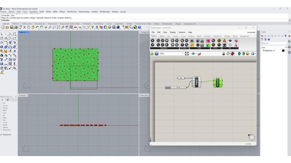 To keep the pattern inside the original boundary, I connected the rectangular surface boundary to the Voronoi component. This restricted the cells to the dimensions of the design area and created a cleaner result suitable for fabrication.
Once the Voronoi geometry was generated, I baked the curves into Rhino for further editing. The resulting lines represented only the center paths of the structure, which would not be suitable for 3D printing because they had no thickness. To solve this, I selected the Voronoi curves and applied the Offset command. By defining an offset distance, I transformed the single lines into enclosed shapes with measurable thickness.
After creating the offsets, I used CurveBoolean to clean intersections and remove unwanted geometry. In some cases, I exploded the curves and manually edited specific areas to improve the overall structure and avoid weak connections that could fail during printing.
With the geometry cleaned and thickened, I joined the curves and verified that all boundaries were closed. This step was essential because open curves can create errors when generating surfaces or preparing files for fabrication.
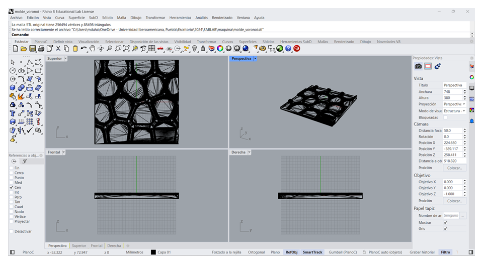
Finally, I converted the closed curves into surfaces using the PlanarSrf command and then applied Extrude Surface to give the pattern a physical thickness. This transformed the 2D Voronoi network into a three-dimensional object that could be exported as an STL file and prepared for 3D printing in Cura.
What became clear throughout the process is that it's not really about following a sequence of commands, but about understanding how each parameter influences the result. By adjusting point distribution, spacing, and thickness, I could move from a purely aesthetic pattern to something that actually works in a physical context. Without that level of control, the design might look interesting on screen but fail when brought into the real world.
Surface → Populate Geometry → Voronoi 2D → Boundary → Bake → Offset → CurveBoolean → PlanarSrf → Extrude → STL
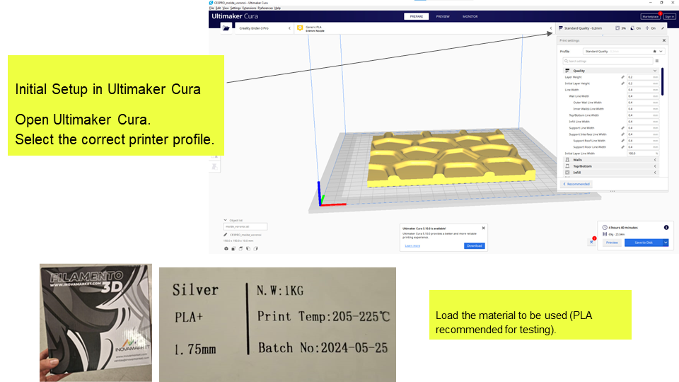
Ultimaker Cura Guide for FabLab Use
When I began testing print quality, wall thickness, and infill, I started by setting everything up in Ultimaker Cura, making sure I was working with the correct printer profile so the settings actually matched the machine I was using. I chose PLA as the base material since it's reliable and easy to work with for calibration tests, and then imported a simple test model—either a calibration cube or a small piece with flat surfaces and defined walls. Starting with something simple helped me focus on how each parameter affected the result, rather than getting distracted by complex geometry too early in the process.
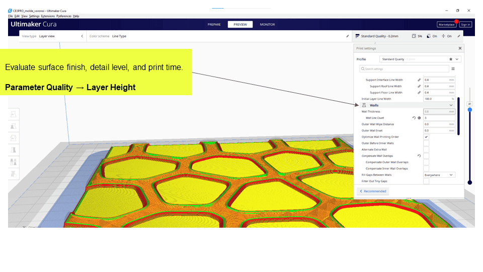
Test 1: Print Quality (Layer Height)
To evaluate print quality and efficiency in Ultimaker Cura, I tested two layer heights: 0.2 mm and 0.4 mm. The 0.2 mm setting produced smoother surfaces and better detail but took longer to print, while 0.4 mm was much faster with more visible layers. Considering surface quality, edge definition, and print time, I chose 0.4 mm as it offers a good balance for functional prototypes.
Test 2: Wall Thickness
To assess structural strength and edge quality in Ultimaker Cura, I tested two wall thickness settings: 0.2 mm and 0.4 mm. The thinner walls at 0.2 mm were too flexible and lacked structural resistance, while 0.4 mm provided better rigidity and more consistent wall formation. Evaluating flexibility, wall integrity, and layer bonding, I found that 0.4 mm offered a more reliable and durable result.
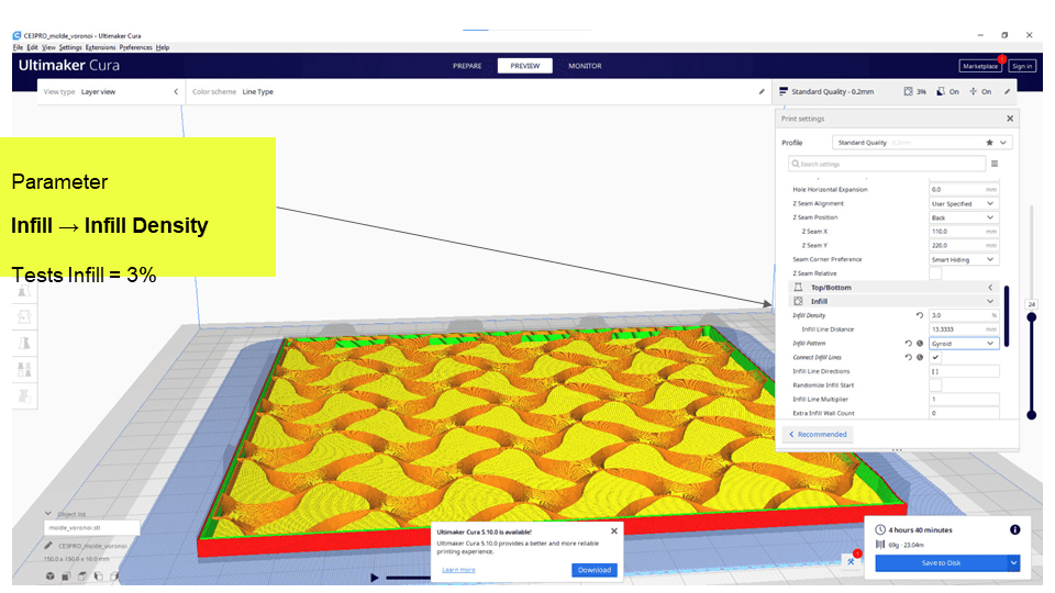
Test 3: Infill Density
To balance weight, strength, and material usage in Ultimaker Cura, I tested a low infill density of 3%. This setting produced a very lightweight piece, but with minimal internal support, making it less suitable for parts that require structural strength.
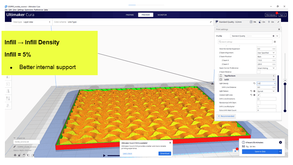
- Infill = 5% – Better internal support, still material-efficient.
I evaluated the infill test in Ultimaker Cura by focusing on structural rigidity, overall weight, and material consumption. With a very low infill like 3%, the piece was extremely lightweight and efficient in terms of material use, but it lacked the rigidity needed for more demanding applications, making it suitable only for non-structural or visual prototypes.
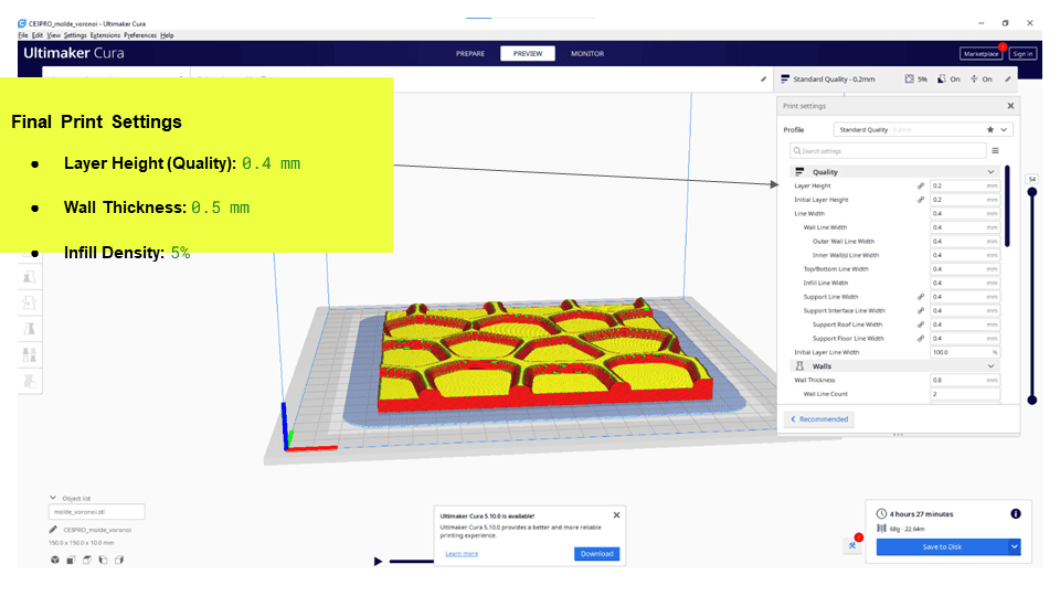
Final Selected Parameters
After testing and comparison, the following parameters were chosen:
| Parameter | Value |
|---|---|
| Layer Height (Quality) | 0.4 mm |
| Wall Thickness | 0.5 mm |
| Infill Density | 5% |
Printer Preparation Guide
1. General Printer Inspection (Before Printing)
Before starting any calibration or print, I make sure the printer is actually in good working condition, because skipping this step usually leads to errors that have nothing to do with slicer settings. I begin by placing the machine on a flat, stable surface and checking the general mechanics: belts need to be properly tensioned—not too loose, not too tight—and the axes should move smoothly without resistance. I also take a moment to look at the rods or rails to ensure they're clean and free of debris.
Then I move to the hotend and nozzle, making sure there's no burnt filament buildup that could affect extrusion. If I notice any clogging or irregular flow, I clean the nozzle, sometimes doing a cold pull to remove residue. After that, I check the filament itself and the extruder: the material should feed smoothly, without brittleness or moisture issues, and the extruder gear needs to be clean and gripping properly, without slipping.
Finally, I prepare the print bed. I clean it with isopropyl alcohol—especially when working with PLA—and avoid touching it afterward to prevent oils from affecting adhesion. I also verify that the build plate is firmly in place and not warped. Taking a few minutes to go through all of this saves a lot of time later, because it isolates problems before they show up in the print.
2. Preheating (Critical Step)
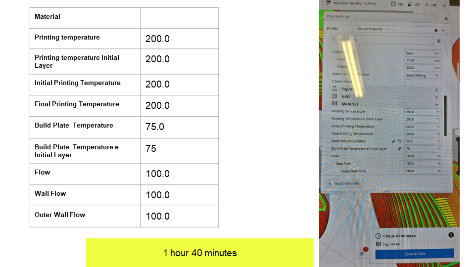
Before calibration, heat the printer to operating temperature:
- Nozzle: 200 °C (PLA)
- Bed: 75 °C
3. Bed Leveling
I start by homing the printer using Auto Home, making sure the nozzle moves correctly without scraping the bed. This helps confirm that the machine is properly aligned. Then I proceed with manual bed leveling using the paper method, adjusting the distance until I feel slight resistance—enough for good adhesion, but without the nozzle pressing too hard against the surface.
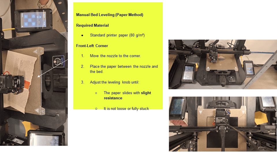
Required Material: Standard printer paper (80 g/m²)
For manual bed leveling, I move the nozzle to each corner of the bed one by one—starting with the front-left—and place a sheet of paper between the nozzle and the surface. At each point, I adjust the leveling knob until the paper slides with slight resistance, not too loose and not completely stuck. I repeat this same adjustment in the front-right, rear-right, and rear-left corners, keeping the feeling consistent across all points. After that, I check the center of the bed to confirm the height is even; if it feels too tight or too loose, I go through the whole cycle again. In practice, it usually takes two or three full passes to get a properly leveled bed.
4. Insert Memory Card
Before starting the print, I insert the SD or microSD card into the printer while it's idle, either on or off. I make sure it's fully seated in the slot and not loose, since a poor connection can cause the file not to load or interrupt the print.

5. Select File
Once the memory card is inserted, I go to the printer's screen and navigate to the print menu—usually labeled Print, Print from SD, or Media. From there, I browse the list of files on the card and select the corresponding .gcode file to start the job.
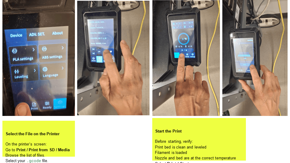
6. Start the Print
Common Issues and Solutions
| Issue | Possible Cause | Solution |
|---|---|---|
| Poor adhesion | Nozzle too high | Lower Z |
| Bed scratching | Nozzle too low | Raise Z |
| Uneven lines | Bed not level | Re-level bed |
| Rough first layer | Excess pressure | Adjust Z-offset |
| --- |