11. Open Source Hardware

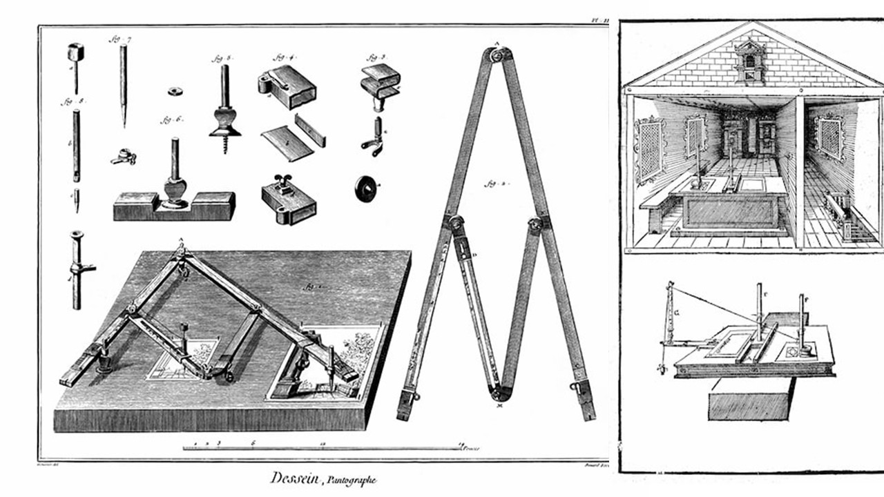
Figure 1: Pantographs, circa 1888. Mechanical drawing devices for scaling and reproducing images. Retrieved from drawingmachines.org
The website drawingmachines.org is a digital archive dedicated to collecting and documenting optical, mechanical, and automated drawing machines used over the past 500 years. Its goal is to uncover forgotten, obsolete, or little-known drawing technologies and to explore the historical relationship between art and technology through primary source materials.
I love the website because it showcases a variety of historical drawing instruments, such as harmonographs, ellipsographs, and camera lucidas, which were early attempts at automating the drawing process. These devices can be seen as precursors to modern CNC machines, highlighting the long-standing human fascination with mechanizing artistic creation.
Research & Ideation
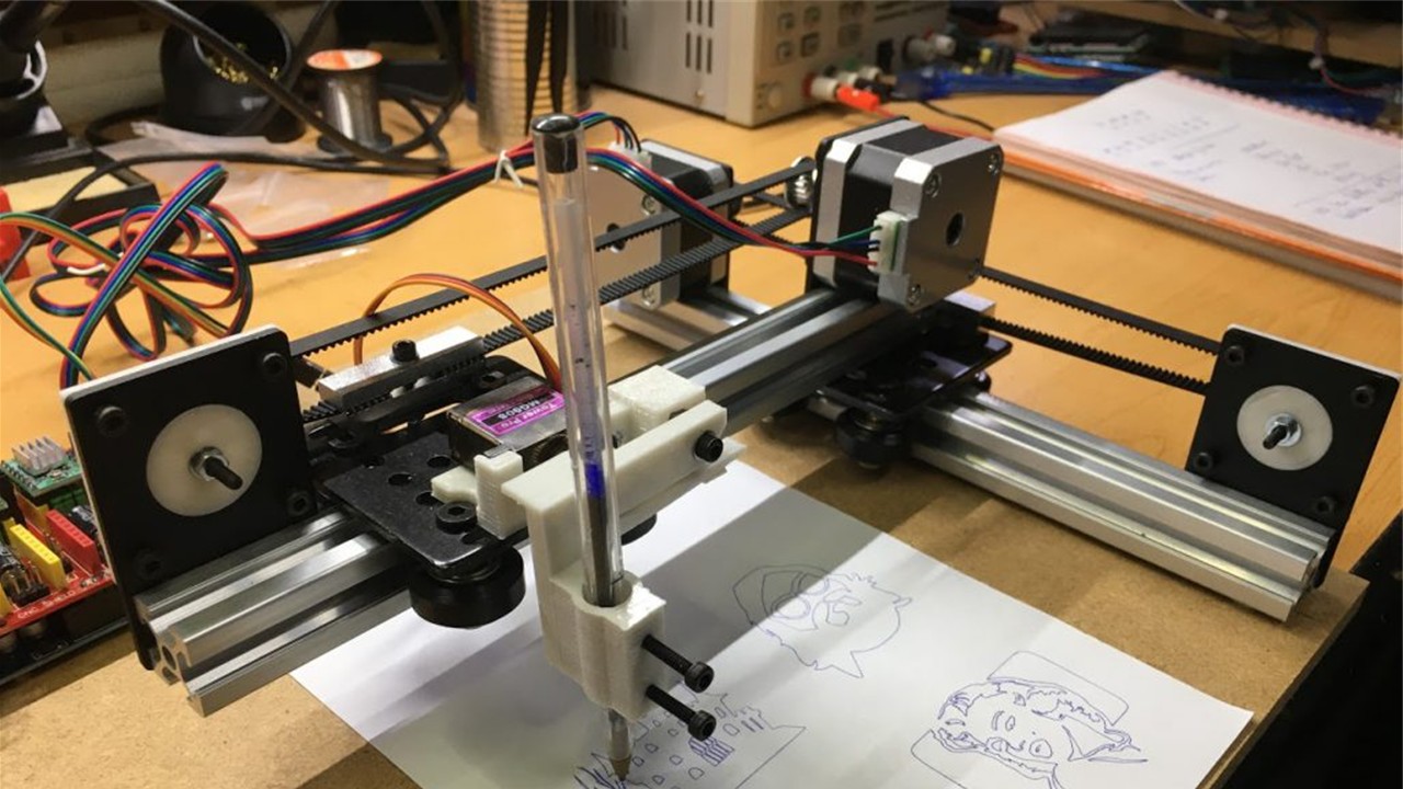
Figure 2: Das, A. K. (2018). How to make an Arduino drawing machine. Retrieved from Arnabkmardas
What is a CNC Machine?
From my perspective, CNC machines are valuable because they give me high precision and consistent results. They help reduce human error, although in reality the error just shifts to design and setup. I can use them for both custom pieces and mass production, which makes them essential in design, digital fabrication, and rapid prototyping.
Common Types of CNC Machines
| Machine Type | Description |
|---|---|
| CNC Milling Machine | Cuts or sculpts solid materials with rotating cutting tools. |
| CNC Lathe | Rotates a piece while a fixed tool shapes or cuts it. |
| Laser Cutter | Uses a focused laser beam to cut or engrave various materials. |
| Plasma Cutter | Cuts through metals using a high-temperature plasma jet. |
| 3D Printer (FDM) | Builds objects layer by layer from melted filament, following digital code. |
Typical Components
| Component | Description |
|---|---|
| Stepper motors | Control movement along X, Y (and sometimes Z) axes with precision. |
| Pen holder | Mount that grips the pen, marker, or brush securely. |
| Controller board | Microcontroller (e.g., Arduino with GRBL) that interprets G-code commands. |
| Belts and pulleys | Mechanism to transfer motion across the machine's frame. |
| Frame | Structural support, often made from aluminum, wood, or 3D-printed parts. |
For me, a CNC drawing machine, or plotter, translates digital designs into physical drawings using a pen instead of cutting tools. To use it, I first create a design in vector software like Inkscape or Illustrator, then export it as a G-code or SVG file. The machine follows those instructions by moving a pen along the X and Y axes (and sometimes Z), drawing the design with high accuracy.
Open-Source CNC Plotters
- Makelangelo Drawing Robot
- DrawBot from PlotterBot
- Final project - Pauline Gamore
References & Inspiration
The project Digital Grotesque by Michael Hansmeyer shows how architectural form can be generated through algorithms, creating highly complex geometries that would be nearly impossible to design manually.
The Plywood CNC Furniture by OpenDesk is a system of furniture designed specifically for CNC fabrication and distributed manufacturing. For a FabLab context, it's relevant because it focuses on efficient 2.5D cutting (flat sheets), precise joinery without screws, and local production. The designs are optimized so they can be cut anywhere with a CNC machine and assembled easily, reducing waste, transport, and complexity.
Tools
Process and Workflow
CNC Redesign for Soft Robotics
Overview
For this project, we redesigned a CNC machine from the lab to create figures from polypropylene sheets, a material suitable for soft robotics. The main challenge was building the machine using recycled components, which required careful inspection due to possible damage or faults. Fortunately, FABLAB Puebla provided access to multiple machines for reuse.
Team Members
- María José
- Aristarco
- Raúl
- Marcela
- Maricruz
Task Distribution
| N | Task | Responsible 1 | Responsible 2 | Responsible 3 |
|---|---|---|---|---|
| 1 | Investigation | María José | Raúl | Maricruz |
| 2 | Parts verification | Raúl | Aristarco | Maricruz |
| 3 | Machine assembly | Raúl | Marcela | Maricruz |
| 4 | Base design | Marcela | Raúl | - |
| 5 | Initial tests | Raúl | Aristarco | Maricruz |
| 6 | Adapter design | Marcela | Maricruz | - |
| 7 | G-code | Aristarco | Maricruz | - |
| 8 | Final tests | María José | Aristarco | Maricruz |
| 9 | Documentation | María José | Raúl | Maricruz |
Why a 3-Axis CNC?
We selected a 3-axis CNC (X, Y, Z) because of its versatility and simplicity:
- Compatible with multiple tools and adapters
- Easily integrable with other systems (e.g., temperature control)
- Capable of cutting, milling, drilling, and engraving
- Less complex than multi-axis machines while still highly functional
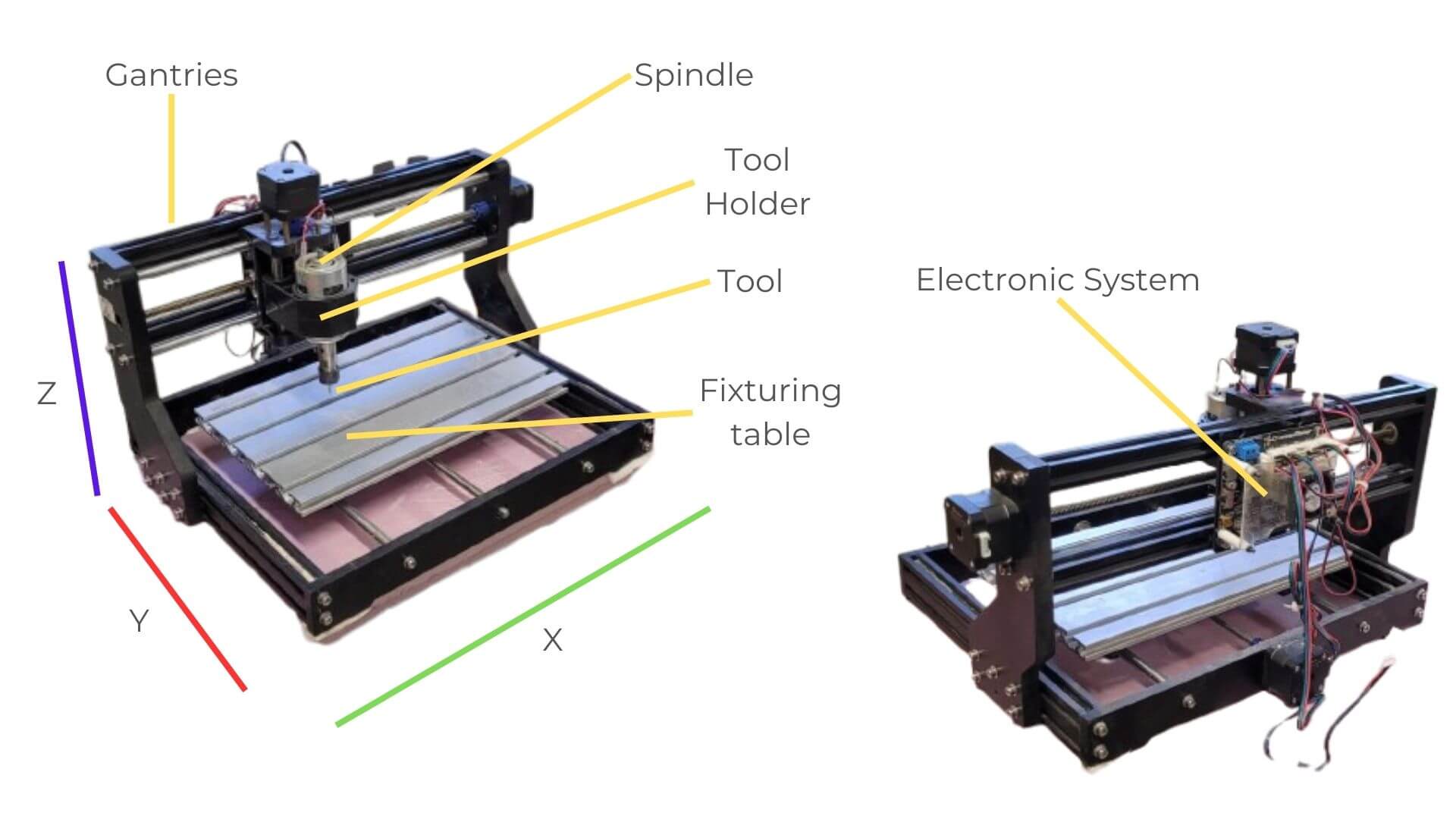
Figure 3: Image created by the team: María José, Aristarco, Raúl, Marcela, and Maricruz
Y-Axis: Components and Functionality
We built the Y-axis using two 10 mm calibrated rods, along which four linear blocks slide, allowing precise and stable movement. We mounted the main plate onto these blocks to create a compact structure, and we included an anti-backlash nut to reduce play. We transmit motion from the motor through a threaded rod connected by a coupling, while the blocks act as linear guides to ensure the bed moves smoothly.
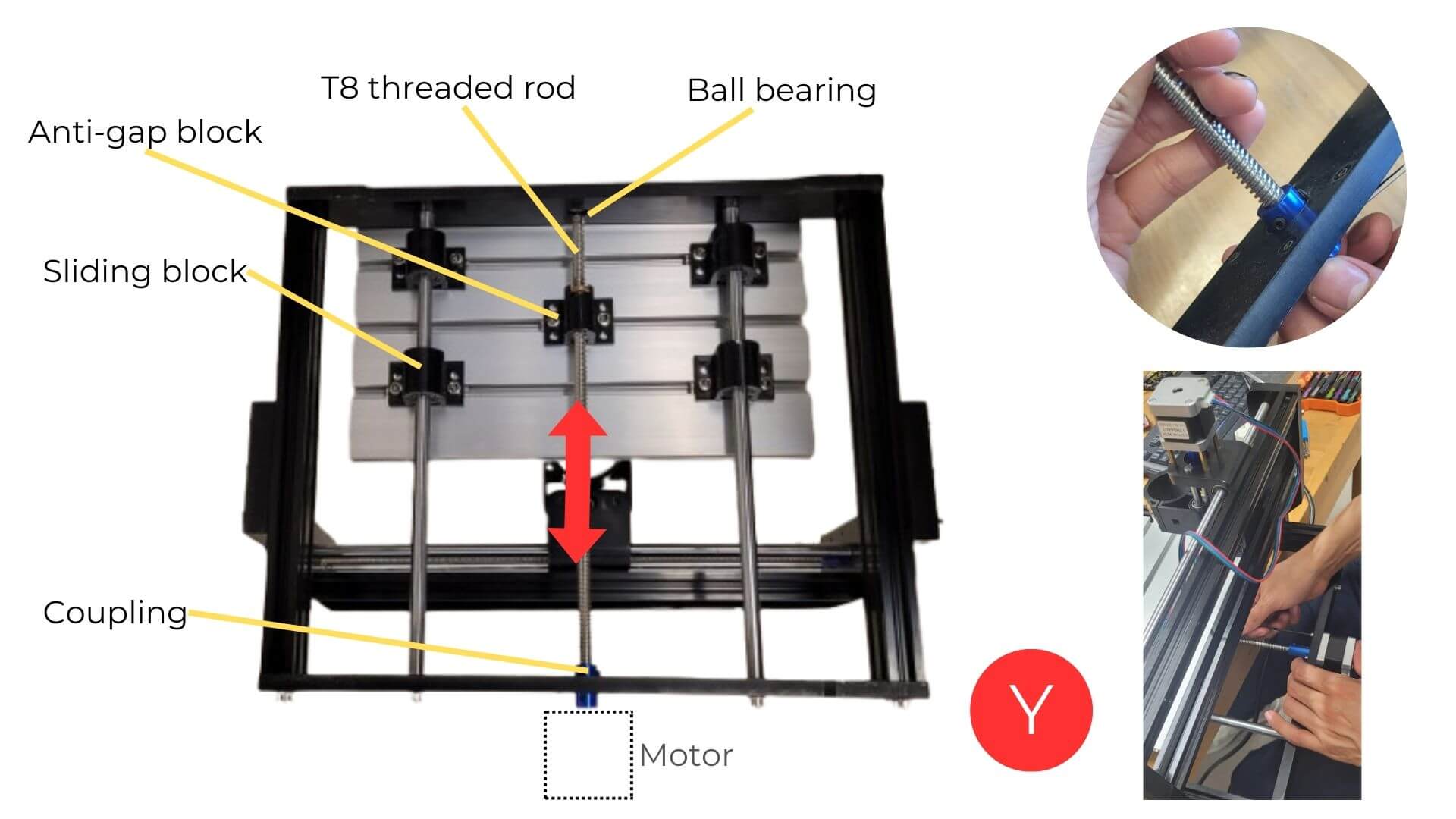
Figure 5: Image created by the team: María José, Aristarco, Raúl, Marcela, and Maricruz
Maricruz and Raúl checked that the leadscrew and other components were in good condition, without deformations that could affect performance. They also integrated a salvaged motor, which should be tested beforehand by connecting it to the control board and driver before installation.
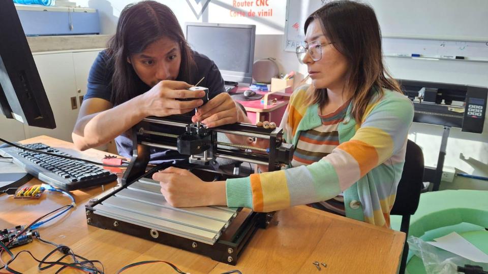
Figure 6: The image shows how Maricruz and Raúl manually checked that the leadscrew and other components were straight and free of dents or deformations.
X-Axis: Components and Functionality
The X-axis is built as a bridge using two chrome rods, support plates, a motor, and metal profiles for structure. The Z-axis body includes the anti-backlash nut, while linear bearings allow it to move smoothly and accurately along the rods.
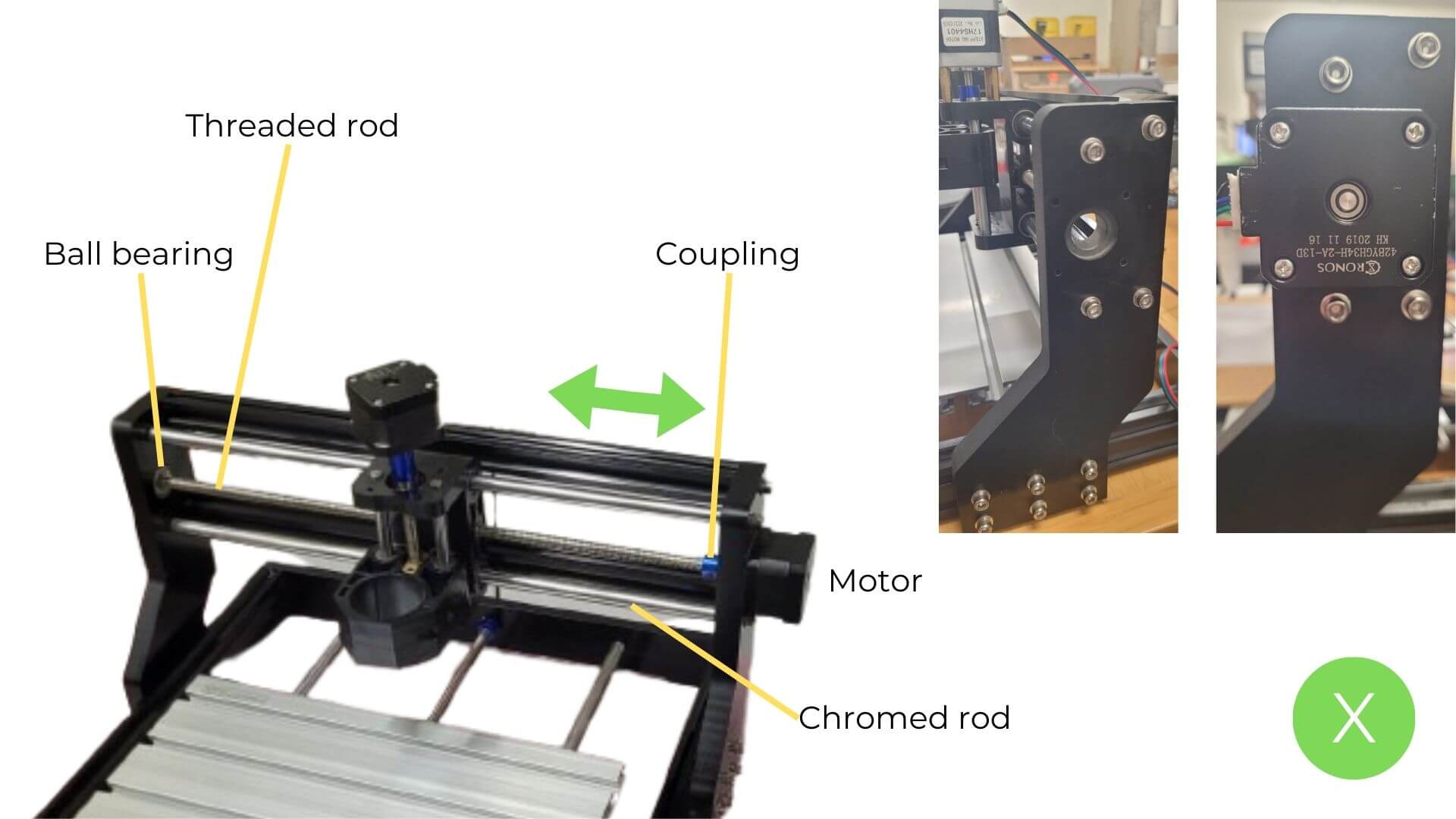
Figure 7: Image created by the team: María José, Aristarco, Raúl, Marcela, and Maricruz
Z-Axis: Components and Functionality
The Z-axis consists of a moving body along the X-axis, incorporating an anti-backlash nut for precise motion. Linear bearings and guides provide stability. During inspection, we identified a key issue: we did not have a compatible motor in working condition.
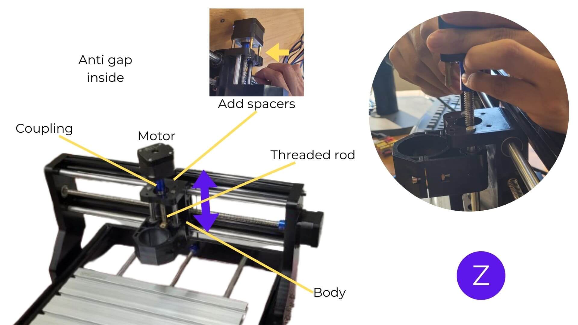
Figure 8: Image created by the team: María José, Aristarco, Raúl, Marcela, and Maricruz
Electronics
We used a GRBL 1.1 Cronos Maker board:
- Compatible with stepper motors (A4988 drivers)
- Supports CNC, laser, and spindle systems
- Controlled via Universal Gcode Sender (UGS)
Key Considerations
- Inspect reused components (pins, soldering, capacitors)
- Test drivers and connections
- Ensure proper power supply (12V–24V)
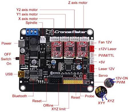
Figure 9: Image created by the team: María José, Aristarco, Raúl, Marcela, and Maricruz
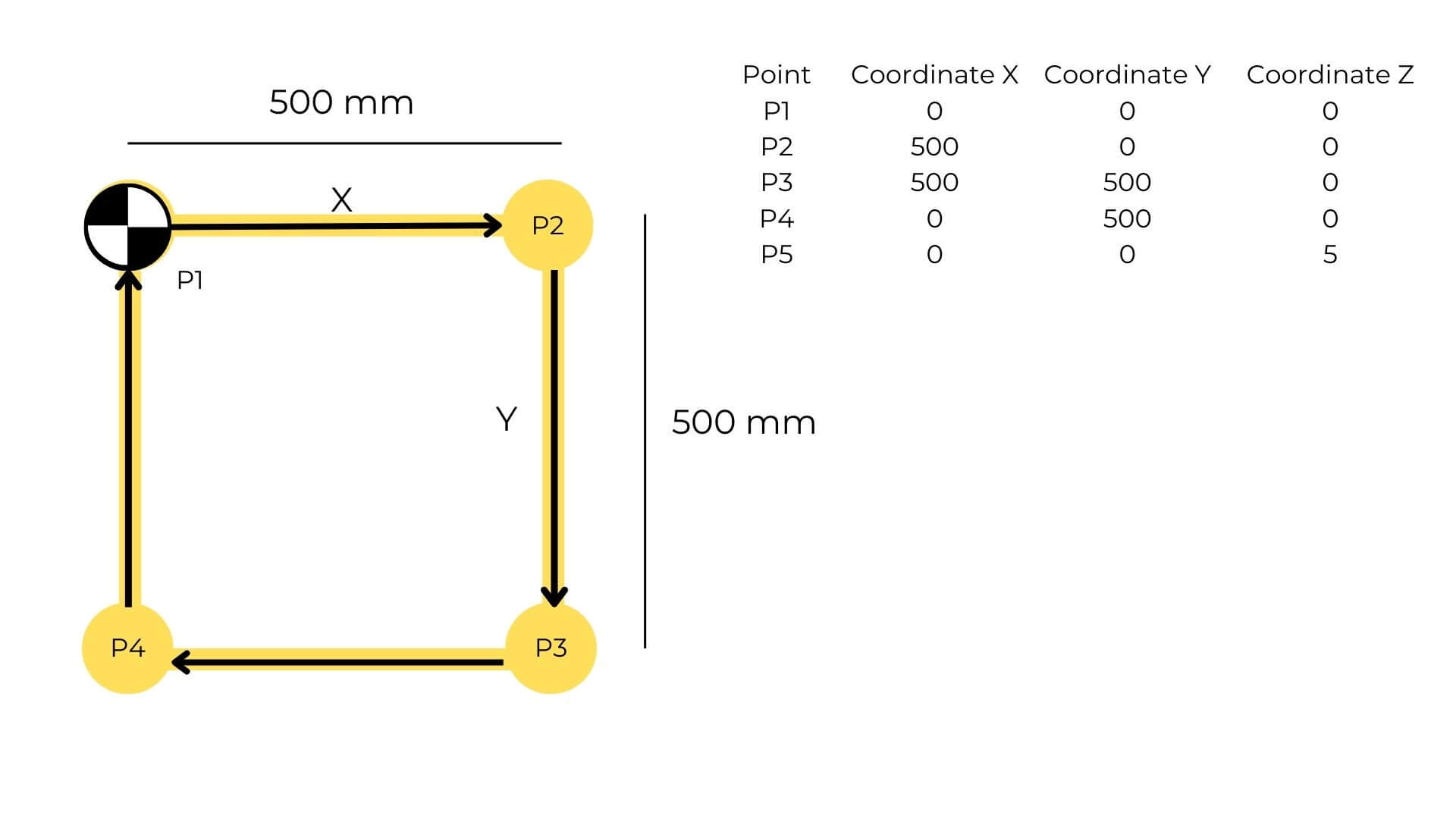
Figure 10: Image created by the team: María José, Aristarco, Raúl, Marcela, and Maricruz
Structural & Electronic Components
| Structural Component | Qty | Electronic Component | Qty |
|---|---|---|---|
| Aluminum profiles | 4 | CNC Controller (GRBL) | 1 |
| Aluminum bases | 4 | A4988 Drivers | 3 |
| Tool holder | 1 | Stepper cables | 3 |
| Fixturing table | 1 | USB cable | 1 |
| Leadscrews | 3 | Power cable | 1 |
| Stepper motors | 3 | ||
| Couplings | 3 | ||
| Linear bearings | 4 | ||
| Rod guides | 4 | ||
| Screws | 32 |
G-Code & Software
- Designed in AutoCAD → exported as DXF
- Toolpaths generated in VCarve
- Controlled with UGS
- Adjusted parameters (e.g., RPM = 0 for no spindle rotation)
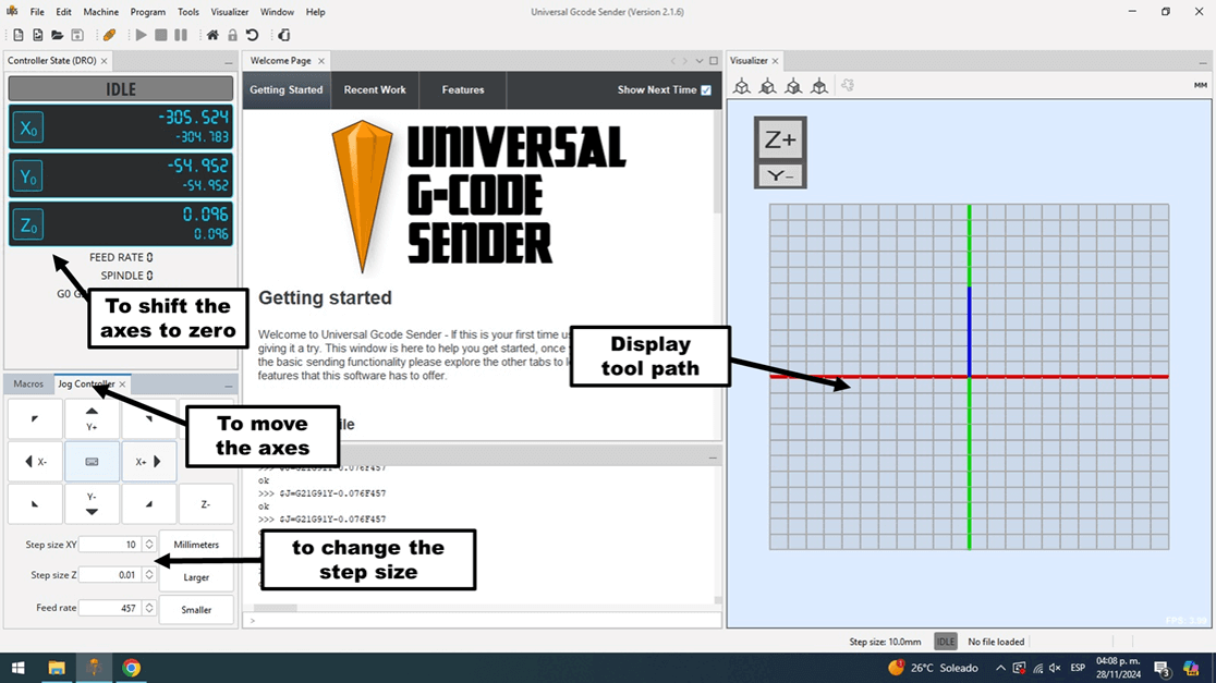
Universal Gcode Sender (UGS) is an open-source tool used to operate CNC machines with controllers such as GRBL or TinyG. It allows me to send and manage G-code instructions in real time, making precise machining possible. Since it runs on Windows, Mac, and Linux, and is easy to use, it's widely adopted by both beginners and professionals.
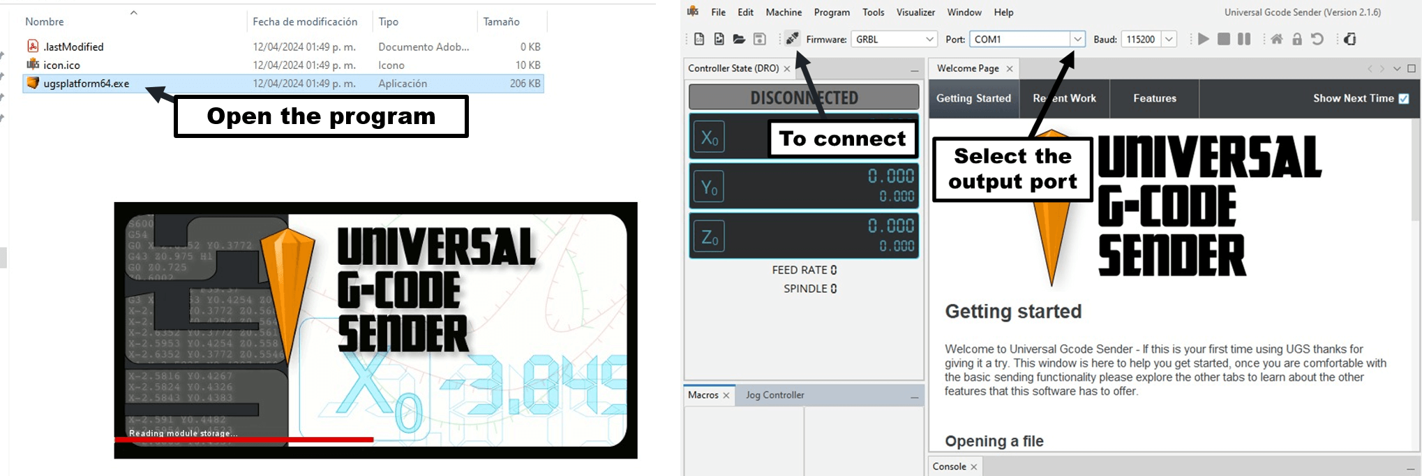
Figure 11: Image created by the team: María José, Aristarco, Raúl, Marcela, and Maricruz
G-Code Basics
Example:
G90G21
G00 X52.58 Y15.02 Z0.00
G1 X0 Y0 F3500
G1 X500 Y0
G1 X500 Y500
G1 X0 Y500
G1 X0 Y0
G00 Z5.00
Explanation
| Code | Description |
|---|---|
| G90G21 | Absolute positioning + millimeters |
| G00 | Rapid movement |
| G1 | Linear movement |
| F3500 | Feed rate |
| Z5.00 | Lift tool |
Base Material
We used TPE to improve the contact between the tool and the material, providing both flexibility and resistance during the process.
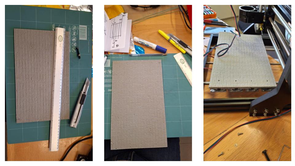
Figure 12: Image created by Marcela
Fabrication Approach
Instead of using traditional milling, we adapted the CNC by integrating a soldering iron as a heat tool, allowing localized heat sealing of polypropylene, inspired by balloon sealing techniques.
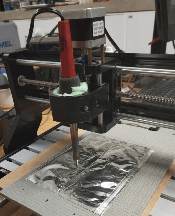
Figure 13: Image created by the team: María José, Aristarco, Raúl, Marcela, and Maricruz
Tool Holder Design
We designed the component in two parts to simplify assembly and added ribs to improve stability. Through iteration, we addressed issues such as interference with the Z-axis motor, excessive support material during 3D printing, and clearance problems.
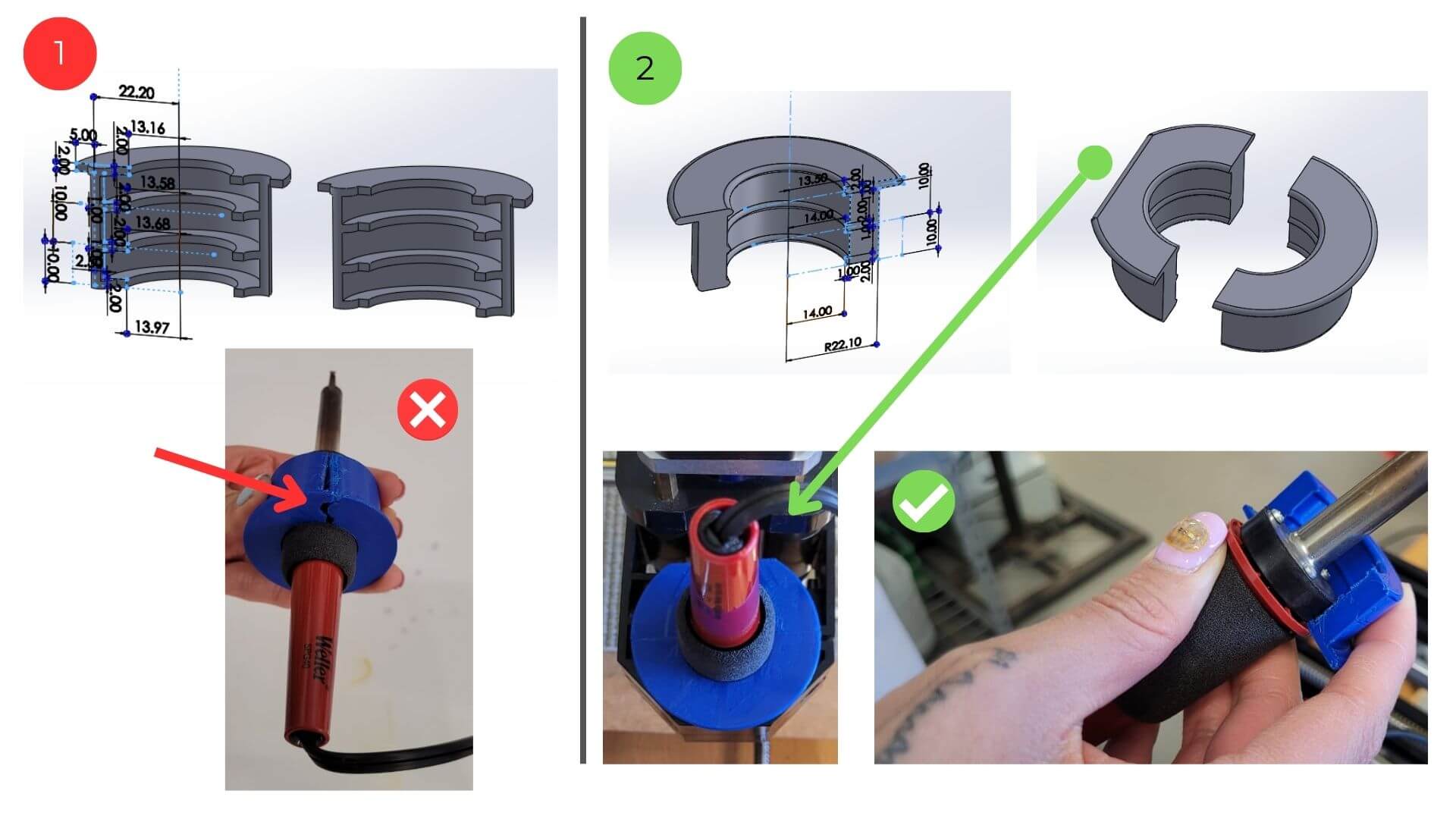 Figure 14: Image created by the team: María José, Aristarco, Raúl, Marcela, and Maricruz
Testing
We calibrated the axis movements and distances, and adjusted the tool height to achieve optimal sealing. During this process, we also identified issues such as misalignment of the work surface.
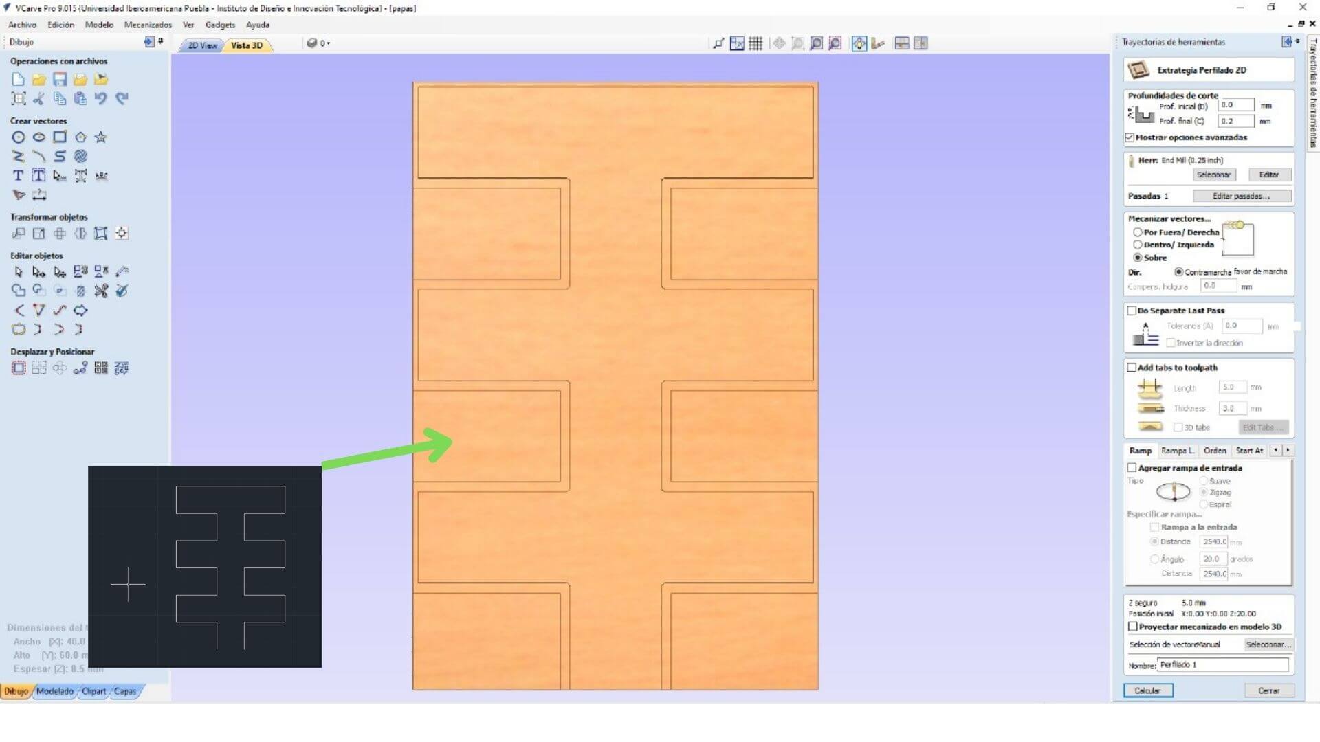 Figure 15: Testing Calibration. Image created by the team: María José, Aristarco, Raúl, Marcela, and Maricruz
The workflow begins by creating the design in AutoCAD, which is then exported as a DXF file. This file is imported into VCarve, where the toolpaths are prepared, and finally, the G-code is generated for machining.
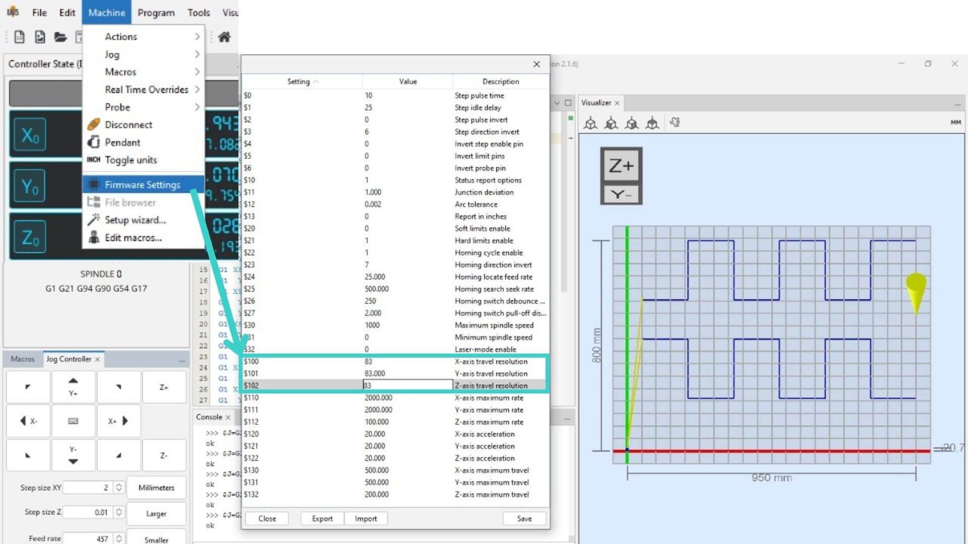 Figure 16: Workflow Diagram. Image created by the team: María José, Aristarco, Raúl, Marcela, and Maricruz
  G21
  G0 Z20.0000
  G0 X0.0000 Y0.0000 S0 M3
  G0 X50.0000 Y425.0000 Z5.0000
  G1   Z-0.7143 F450.0
  G1 X200.0000   F3500.0
  G1  Y200.0000
  G1 X350.0000
  G1  Y425.0000
  G1 X500.0000
  G1  Y200.0000
  G1 X650.0000
  G1  Y425.0000
  G1 X800.0000
  G1  Y200.0000
  G1 X950.0000
  G1  Y500.0000
  G1  Y800.0000
  G1 X800.0000
  G1  Y575.0000
  G1 X650.0000
  G1  Y800.0000
  G1 X500.0000
  G1  Y575.0000
  G1 X350.0000
  G1  Y800.0000
  G1 X200.0000
  G1  Y575.0000
  G1 X50.0000
  G0   Z5.0000
  G0 Z20.0000
  G0 X0.0000 Y0.0000
  M30
Temperature Settings
We started with a high power range (5–40 W), which proved too aggressive, and later adjusted it to a medium range (3–20 W) for better control.
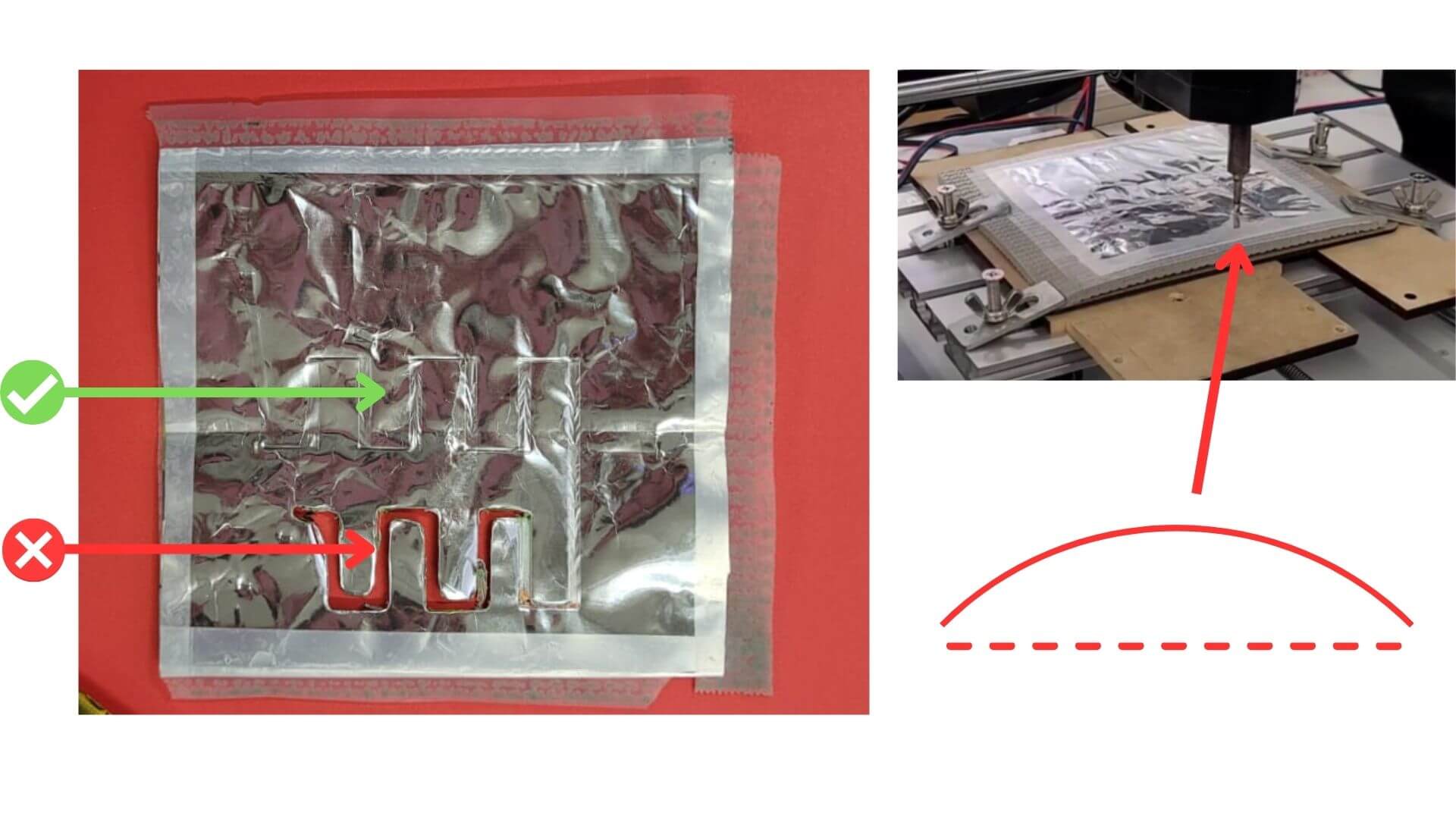 Figure 17: Temperature setting. Image created by the team: María José, Aristarco, Raúl, Marcela, and Maricruz
Heat sealing works by applying heat to plastic surfaces until they melt and bond, creating airtight joints. Instead of using a conventional sealing method, we adapted the process by incorporating a soldering iron, which allowed us to apply heat in a more localized and controlled way, achieving greater precision.
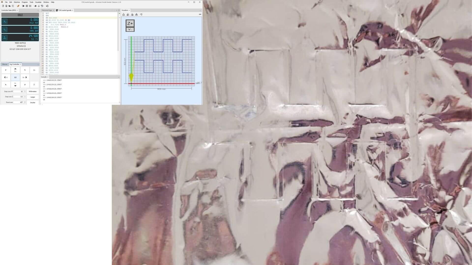 Figure 18: Heat Sealing Result. Image created by the team: María José, Aristarco, Raúl, Marcela, and Maricruz
In the first adapter design, we created a two-part assembly with internal ribs and a top tab for stability. However, this version presented several issues, including interference with the Z-axis motor, difficulty removing support material after 3D printing, and tight tolerances that affected assembly.
To address these problems, we reduced the size of the ribs, increased clearances, and adjusted the overall height. As a result, the final version achieved a stable and functional design, with no displacement during operation.
Video 1: Video created by Maricruz
Notes / Credits
- Collaboration with team members
- Support from FabLab Puebla
- Documentation built with MkDocs