8. Soft Robotics

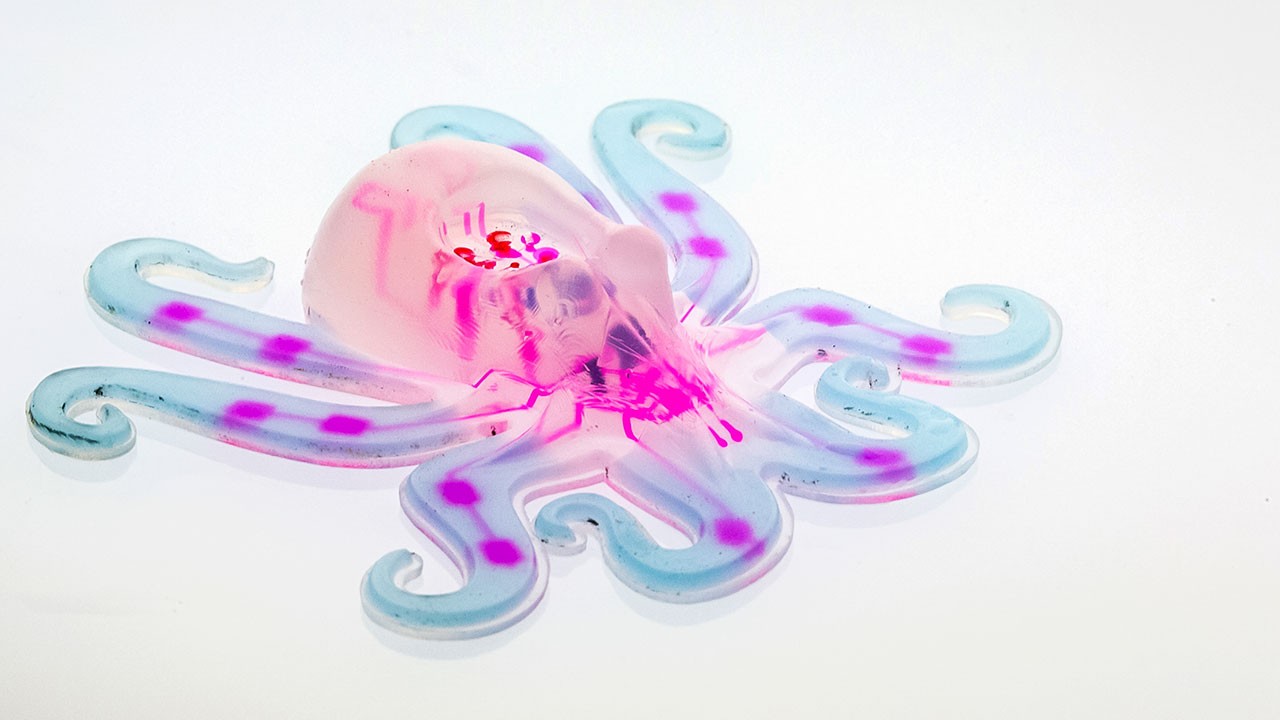
Figure 1: Octopus retrieved from Technology review
Research
Soft robotics is an approach in robotics focused on designing and building robots with soft and flexible materials, inspired by biology and the properties of living organisms. Unlike traditional robots, which are usually made from rigid materials like metal or hard plastic, soft robots use elastic and adaptable materials such as silicone, rubber, or even smart materials that can change shape.
These soft robots are designed to be safe for close interactions with humans, making them ideal for delicate tasks or environments where rigid materials might be harmful or inefficient. For example, soft robots can be used in medical applications, like prosthetics that adapt to the natural movements of the body, or in underwater exploration, where flexible materials allow the robot to move more fluidly and conform to uneven surfaces.
Soft robotics also mimics the movements of living beings, such as the stretching of an octopus tentacle or the grip of a human hand, enabling them to perform complex tasks with a gentle, adaptable touch.
Robert Wood – Harvard University: Wood leads the Wyss Institute for Biologically Inspired Engineering, where he researches soft robotics and the design of robots inspired by living organisms. His team has developed soft robots and microrobots capable of performing complex movements, inspired by insects and octopuses.
Daniela Rus – MIT (Massachusetts Institute of Technology): As director of the Computer Science and Artificial Intelligence Laboratory (CSAIL), Rus has led research on soft robots, developing flexible, autonomous, and reconfigurable devices. Her team has created everything from soft robotic arms to edible robots.
George M. Whitesides – Harvard University: A chemist and pioneer in soft robotics, Whitesides has been instrumental in developing soft robots made from materials like silicone and rubber, applying principles of materials chemistry to create flexible and accessible robots in terms of manufacturing.
Cecilia Laschi – BioRobotics Institute at the Sant'Anna School of Advanced Studies, Italy: Laschi is known for her research in bio-inspired robotics, especially in robots that mimic the movements of marine creatures such as octopuses. Her research has contributed to the development of flexible, underwater robots.
Fumiya Iida – University of Cambridge: Iida leads the Bio-Inspired Robotics Laboratory, where he explores soft and bio-inspired robotics, emphasizing how flexible materials and designs can improve robot adaptability and responsiveness.
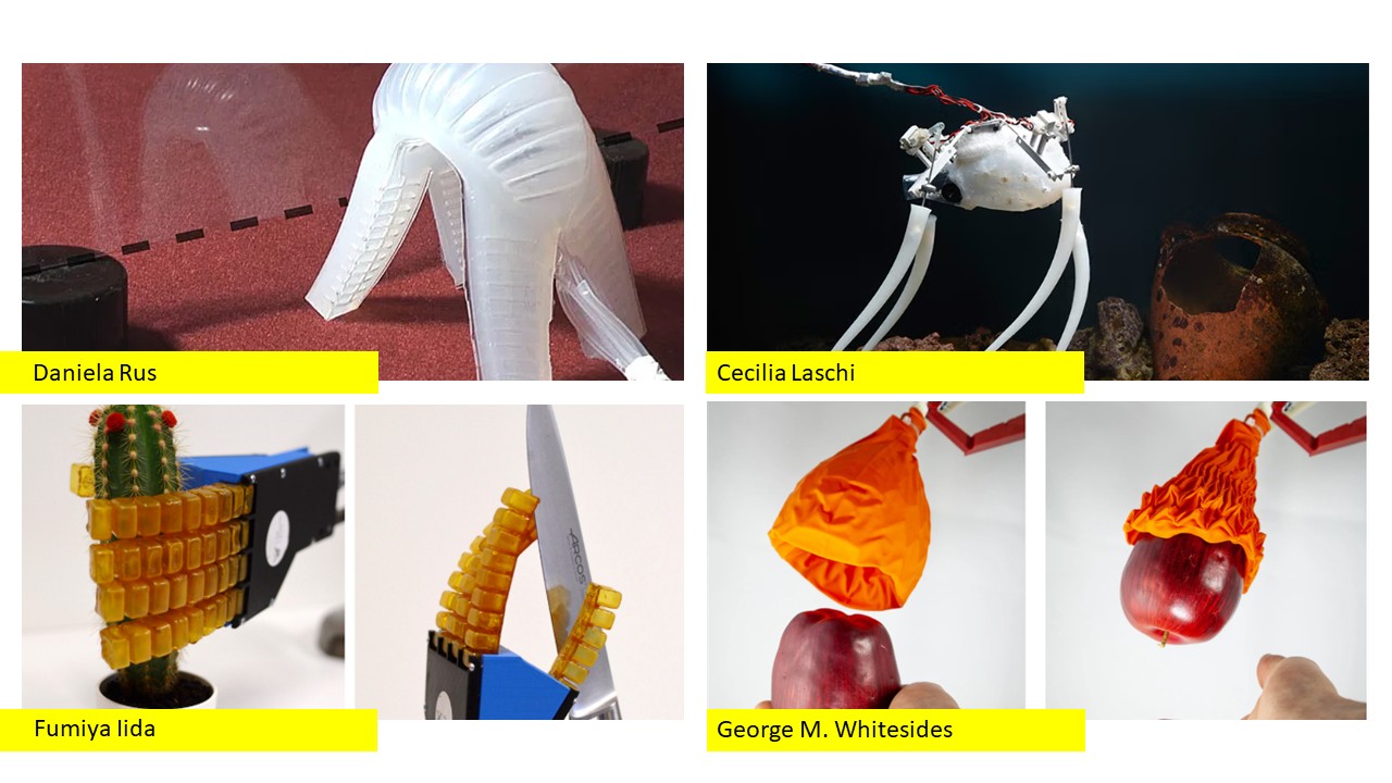
Figure 2: Soft robotics collage, from left to right: Daniela Rus, Cecilia Laschi, Fumiya Iida, George Whitesides.
References & Inspiration
Breaking Techno-Mediated Habits explores how technology, particularly networked devices, impacts our spatial experience and sociability through the concept of 'extended cognition,' where the body and its technological extensions expand cognitive abilities. In an era of rapid technological evolution, our behaviors and interactions are increasingly shaped by devices, leading to new, sometimes unconscious, habits. The work introduces speculative inflatable devices designed to disrupt or generate new tech-driven behaviors, fostering alternative ways to interact with technology and our environments.
The prototypes address various aspects of modern life, such as work, mobility, air quality, and social diversity. Devices like 'Lax' interrupt stressful workflows in workplaces, 'Detext' encourages context awareness while on the move, 'Airborne' monitors air pollution, 'Meetspace' facilitates diverse social encounters, and 'Z-shell' promotes mindful bedtime rituals. These speculative designs aim to challenge our habitual interactions, encourage self-reflection, and inspire a more conscious relationship with our technologies and spaces. By using design fictions, the work pushes for a critical reevaluation of the impact of networked life on our daily routines and the spaces we inhabit.
Detext is meant to remind the user to look up from their phone in instances like walking or driving by inflating to lift the head upward. Meetspace is a tangible interface that exploits our habitual online 'filter bubbles' in reverse to initiate encounters that celebrate socio-political diversity in urban space.
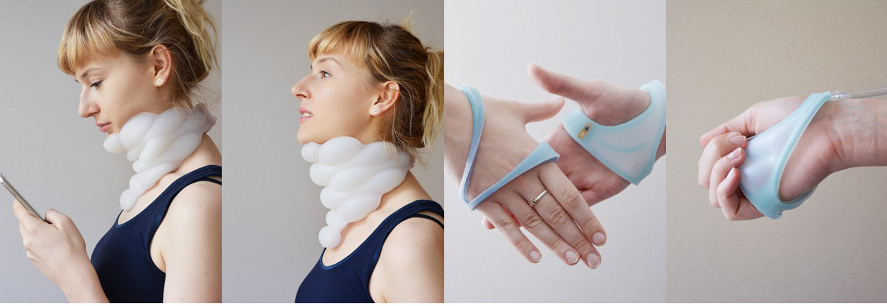
Figure 3: Detext on the right, Meetspace on the left
Jiabao Li is an assistant professor of design at the University of Texas at Austin. Her work focuses on topics such as climate change, interspecies co-creation, human technology, and building a sustainable and just future. She utilizes a variety of media, including wearable technology, robotics, AR/VR, projections, software, and installations.
She is the co-founder and product director of Endless Health and was a researcher at Apple for four years, contributing to the development of technologies such as the Apple Vision Pro. Her work has been exhibited internationally at venues like MoMA, the Venice Architecture Biennale, and Ars Electronica. She has received multiple awards, including Forbes China 30 Under 30 and the iF Design Award.

Figure 4: Tactile Vision
Resources
- Soft robotics: new perspectives for robot bodyware and control
- Octobot: A Soft, Autonomous Robot
- Soft Robotics Toolkit
Process and Workflow
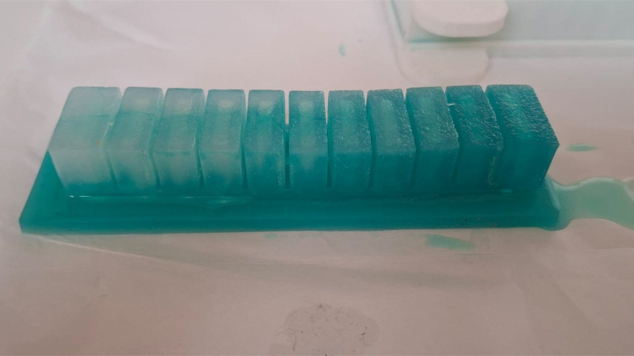
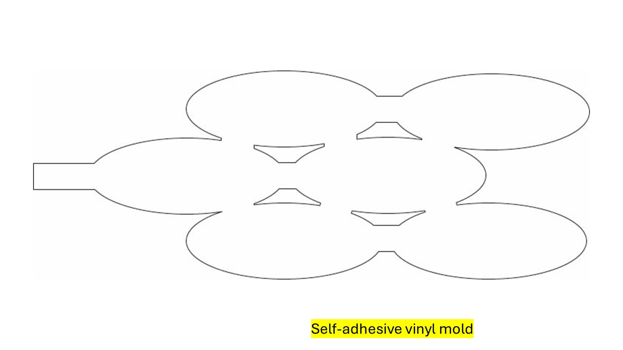
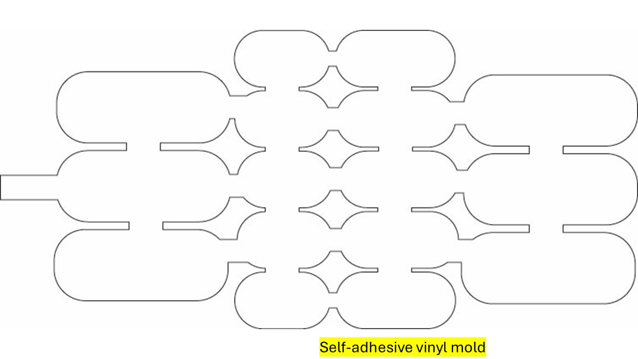
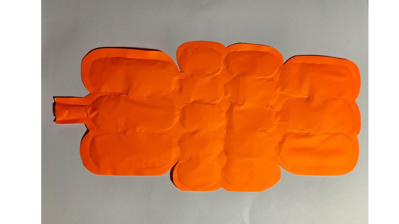
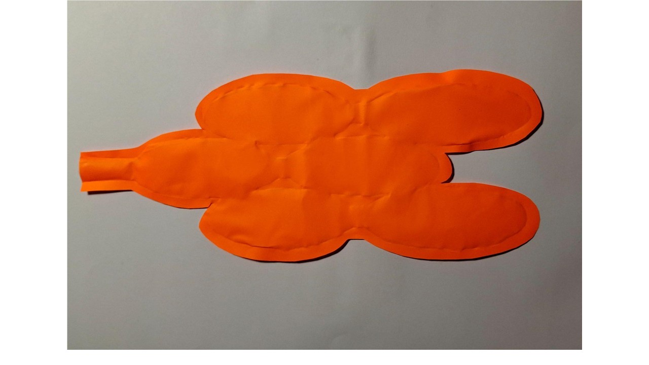
I experimented with three different geometric configurations using heat transfer vinyl and baking paper to define the internal inflation space. I started by cutting simple shapes—circles, triangles, and squares—in different sizes, using them as modular elements rather than a single continuous form. The idea was not only to build a shape, but to explore how geometry affects airflow and deformation.
Instead of stacking them directly, I layered the pieces with baking paper in between to create controlled spacing. This separation was key, since it defines where air can expand and how pressure is distributed inside the structure. Once arranged, I applied heat to bond the vinyl layers, locking the geometry while preserving internal cavities.
What became clear during testing is that thickness and shape distribution directly influence behavior. Areas with more layers tended to inflate more slowly but hold stronger, more stable volume, while thinner sections responded faster and remained more flexible. The air didn't distribute evenly—it naturally moved toward the path of least resistance, which created uneven but interesting deformation patterns. This resulted in a dynamic form where bulging and flexibility coexist, depending entirely on how the layers were arranged.
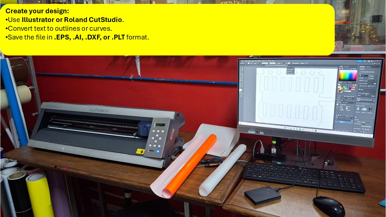
Creating a Soft Robot Using Adhesive Vinyl and Parchment Paper
I worked on building a small soft robotics prototype using adhesive vinyl and parchment paper, focusing on a simple and accessible approach that is well suited for quick experiments or introductory explorations in soft robotics.
To get started, I used adhesive vinyl—ideally in a black or translucent finish because it tends to behave more consistently when flexing—along with parchment paper, which helped me define spacing between layers. I prepared the shapes using scissors or a craft knife, depending on the level of precision needed, and kept a clean work surface to make assembly easier.
For bonding and sealing, I relied on liquid silicone, and in some cases strong glue when the connection did not require flexibility. To introduce and control airflow, I used a small air pump or syringe, sometimes connected through small tubes when a more stable air path was necessary. I also used masking tape or double-sided tape to temporarily hold elements in place during assembly.
In certain cases, especially when working with vinyl layers, I used a soldering iron to create or reinforce thermal seals, ensuring that the air chambers remained closed and controlled. Once everything was assembled, I connected the system to an air source and tested how the structure responded to inflation, observing how the combination of materials and internal spacing affected movement and deformation.
Step 1: Design the Soft Robot
I started by defining the form my soft robot would take, keeping in mind that its movement depends on how it deforms through internal air pressure. Instead of overcomplicating the design, I focused on something simple and functional, like a small arm or finger that could bend when inflated. I sketched the structure first—either on paper or digitally—to visualize how the chambers would expand and where the movement would happen. From the beginning, I considered the behavior of the materials, since both the vinyl and parchment paper would act as the flexible layers that respond to pressure. This helped me think not just about shape, but about how the robot would actually move once fabricated.
Step 2: Cut the Adhesive Vinyl
Once I had the design defined, I moved on to cutting the pieces from the vinyl, following the shapes I had planned. If I didn't have access to a cutting plotter, I simply used scissors or a craft knife, taking care to keep the cuts as clean and precise as possible. While cutting, I made sure to leave enough space in the design to allow for deformation, since the material needs room to expand when air is introduced. I also worked with at least two layers of vinyl to give the structure enough strength, ensuring it could handle internal pressure without tearing while still remaining flexible enough to move.
Step 3: Create the Air Chambers
The air chambers are what allow the robot to move, so I worked with two layers of vinyl, sealing them together while leaving a small opening to insert air. I made sure not to glue everything flat, keeping an empty space between the layers so the chamber could inflate. To have more control over movement, I also considered dividing the interior into multiple chambers, allowing different parts to expand in a more controlled way.
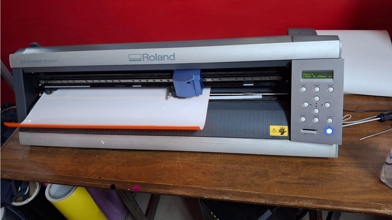
Tutorial: Cutting Vinyl with a Roland CAMM-1 Servo GX-24
Materials and Tools Needed
- Roland CAMM-1 Servo GX-24 vinyl cutter
- Adhesive vinyl
- Transfer tape (optional, for stickers)
- Squeegee or spatula
- Roland CutStudio software (or CorelDRAW/Illustrator with plugin)
- PC with USB connection
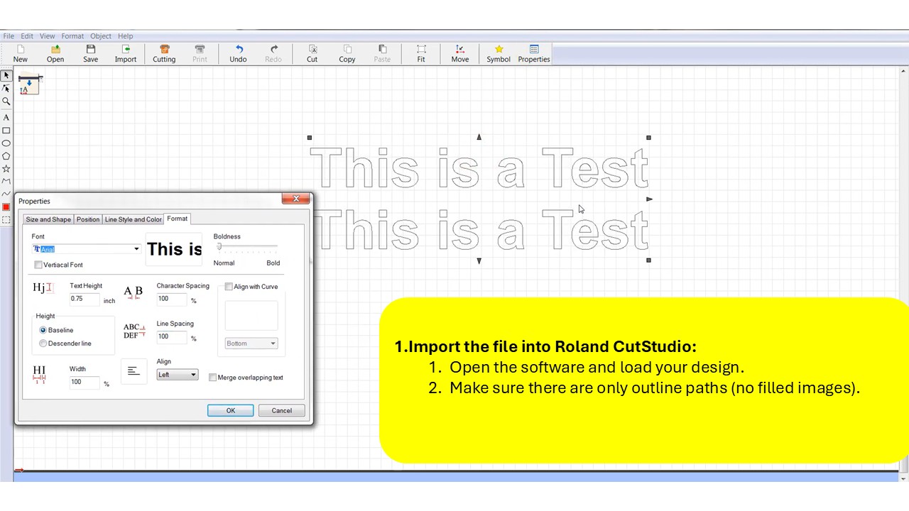
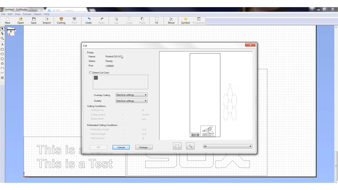
Preparing the Cutting File
I began by creating the design in a vector-based program like Adobe Illustrator or Roland CutStudio, making sure everything was clean and ready for cutting. This meant converting any text into outlines or curves, so there wouldn't be issues with fonts later on, and saving the file in a compatible format such as .EPS, .AI, .DXF, or .PLT. Once the design was ready, I imported it into CutStudio, where I checked that the file contained only outline paths—no filled shapes—since the cutter follows lines, not surfaces.
Setting Up the Vinyl in the Cutter
Load the vinyl into the machine
- Lift the pinch roller lever.
- Insert the vinyl with the adhesive side facing down.
- Adjust the pinch rollers within the white marks.
- Lower the lever to secure the material.
Select the material type on the cutter
- On the control panel, choose
"SHEET"if using a sheet, or"ROLL"if using a roll. - Press
ENTERso the machine can measure the vinyl.
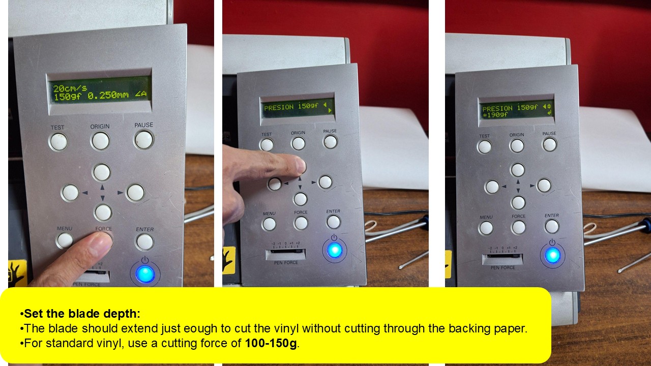
Configuring and Running the Cut
Once the design was ready, I moved into Roland CutStudio to configure the cut. I adjusted parameters like speed and force depending on the material—usually working within a range of 20–30 cm/s for cleaner, more precise cuts, and around 30–60g of force depending on the vinyl thickness. After that, I positioned the design within the cutting area, checked the orientation, and sent the file to the cutter.
When the machine finished, I carefully removed the vinyl and began the weeding process, using a spatula to take out the excess material and reveal the final design. If the application required it, I used transfer tape to lift and place the design onto another surface, making sure everything stayed aligned and intact.
Soft Robotic Gripper Tutorial
A step-by-step guide to building your own soft robotic gripper using Ecoflex silicone and 3D-printed molds.
Materials Needed
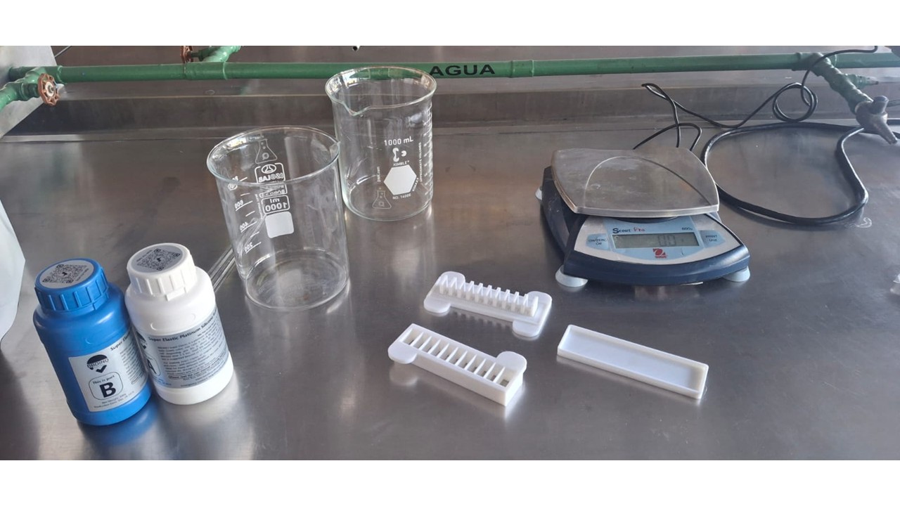
For the Silicone Actuators
- Ecoflex 00-50 (or Ecoflex 00-30)
- Cooking oil (as mold release)
- 3D printed molds
- Syringes and silicone tubing (1/8" inner diameter recommended)
- Masking tape or duct tape
- Hot glue gun (to seal the molds)
- Cardboard or acetate (for the gripper base)
- Strong adhesive (super glue or silicone glue)
- Wooden stick (popsicle stick) for mixing
- Digital scale or measuring cups
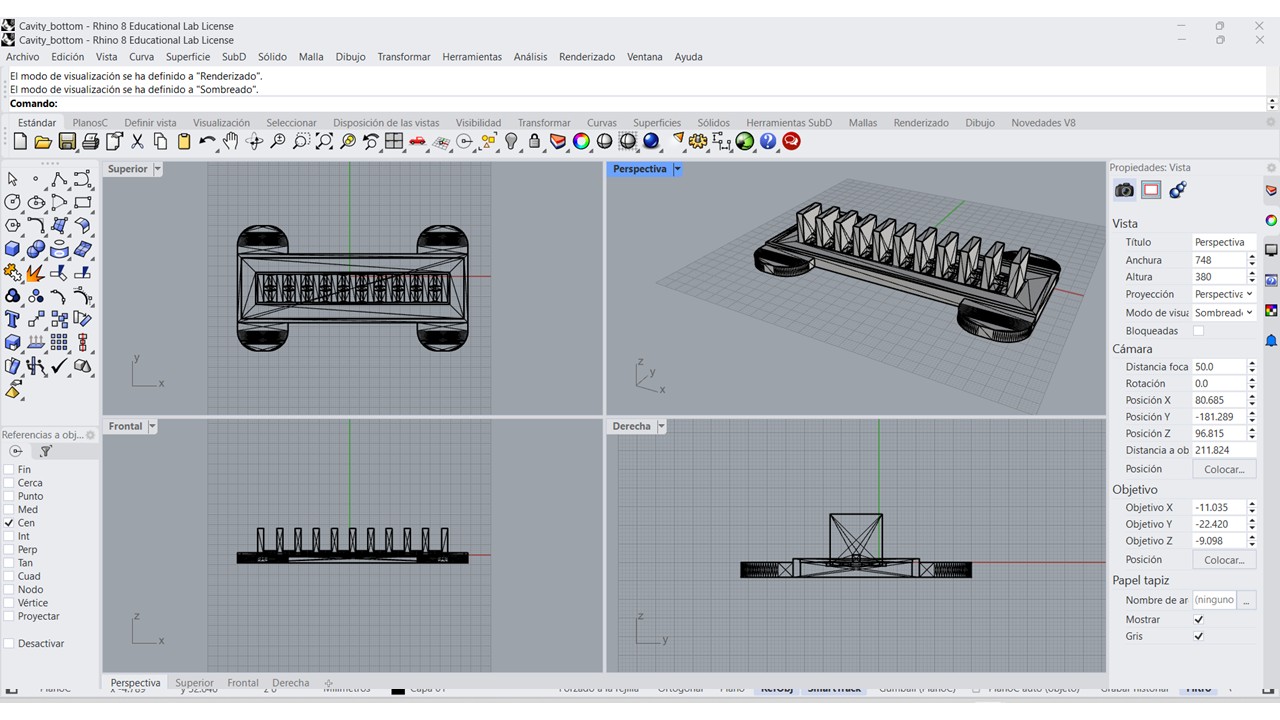
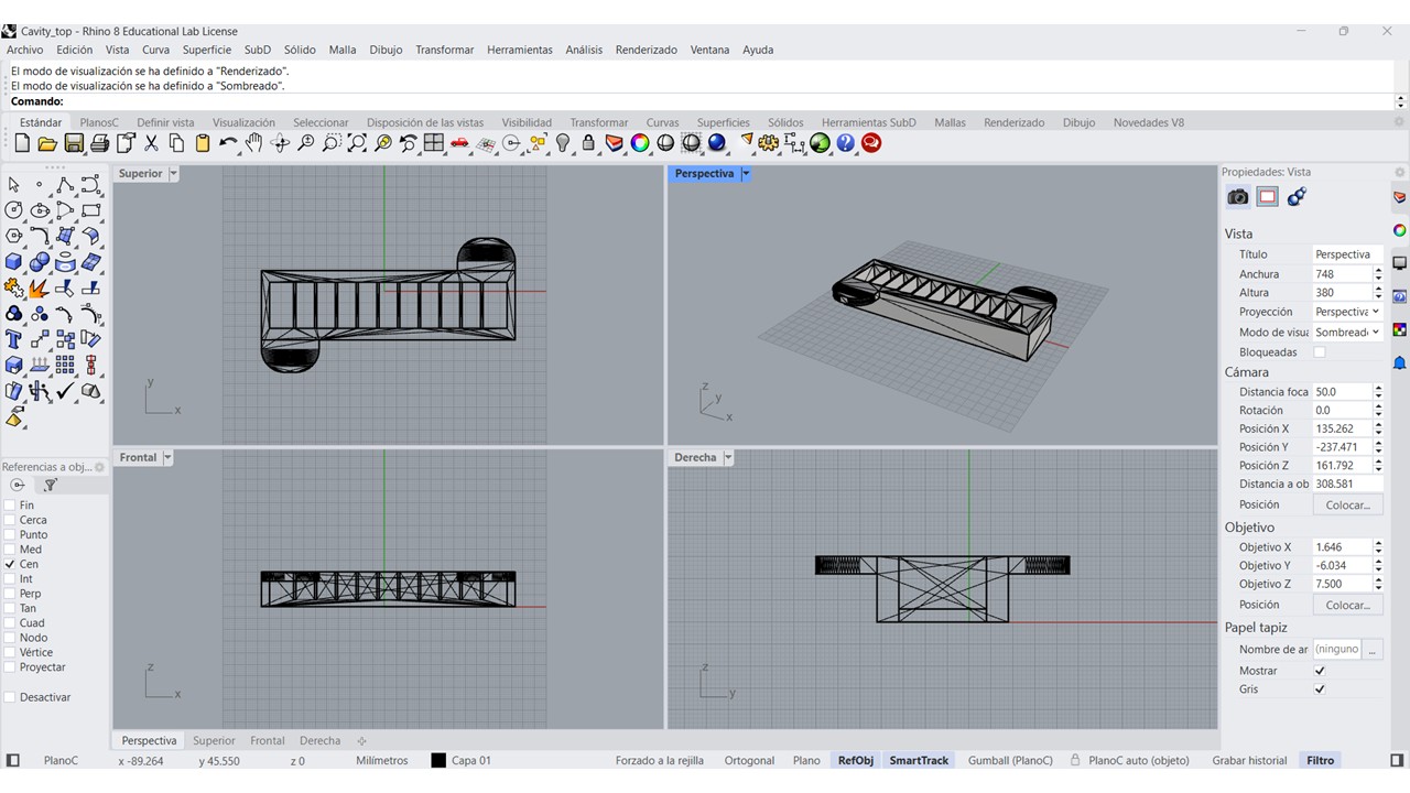
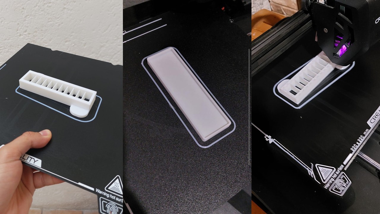
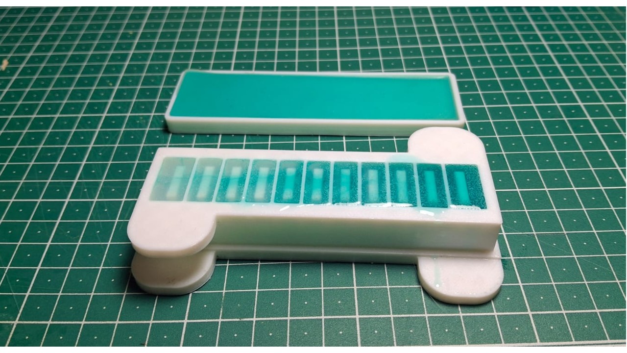
Step 1: 3D Print the Molds
I started by downloading the STL files and 3D printing both parts of the mold—the bottom and the top. Once printed, I checked that they fit together properly, making sure the alignment was snug and precise, since any gaps or misfit would affect the final result.
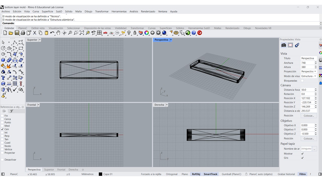
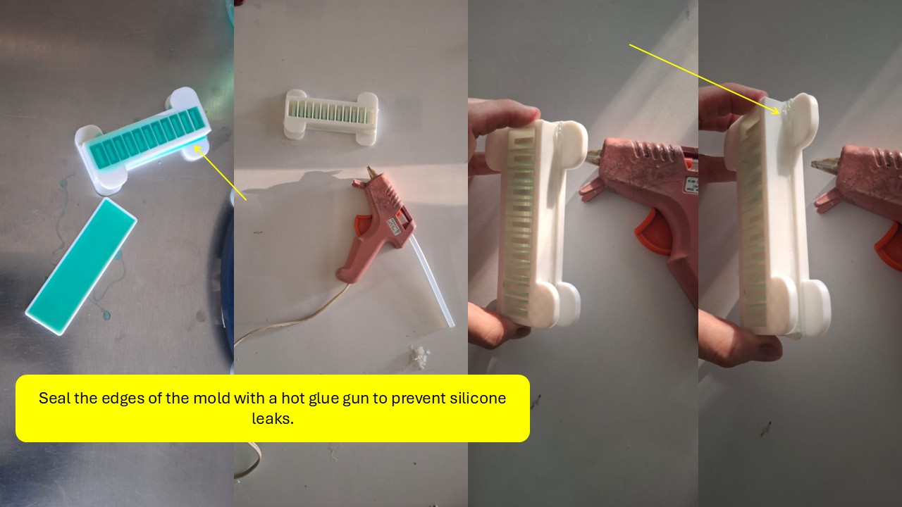
Seal the edges of the mold with a hot glue gun to prevent silicone leaks.
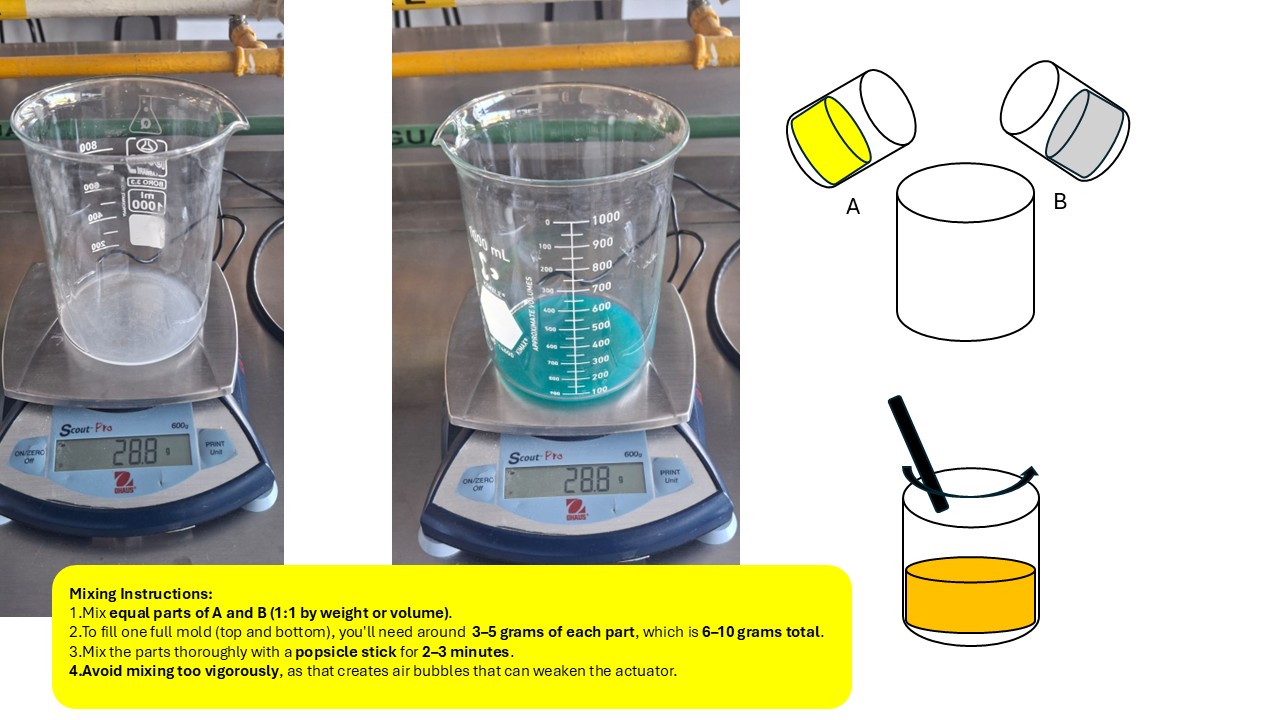
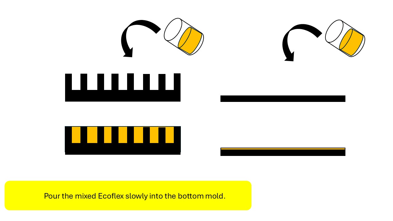
Step 2: Mix and Pour the Silicone
Next, I prepared the silicone by mixing Ecoflex Part A and Part B in a 1:1 ratio by weight, stirring slowly for a few minutes to avoid introducing too many air bubbles. Once the mixture was ready, I applied a thin layer of cooking oil inside the mold to act as a release agent, making demolding easier later on. I then poured the silicone carefully into the bottom mold, trying to keep the flow steady to minimize trapped air. After that, I aligned the top mold and placed it on top, securing both parts with tape or clamps to keep everything in position. Finally, I let the silicone cure for at least four hours, allowing it to fully set before opening the mold.
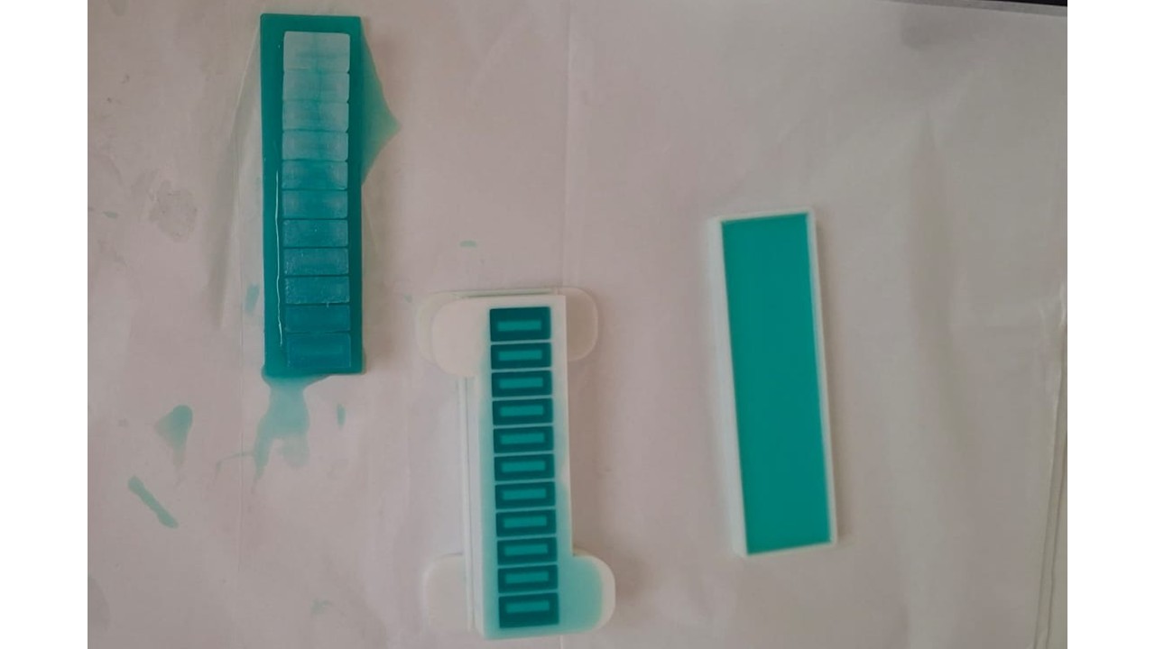
Step 3: Demold and Clean
Once the silicone had fully cured, I carefully removed the actuator from the mold, taking my time to avoid any tearing or deformation. After demolding, I washed the piece with warm water and mild soap to remove any remaining oil used as a release agent. Finally, I let it dry completely before handling or assembling it further.
Step 4: Seal the Base
After demolding and cleaning, I sealed the base of the actuator to make sure it was fully airtight. I did this by applying a thin layer of Ecoflex or attaching a pre-cured silicone sheet to close the bottom. I paid special attention to the edges, since any small gap could cause air leakage and affect the inflation behavior. Once sealed, I let it set completely before moving on to testing or assembly.
Step 5: Connect the Air Tubing
To finish the actuator, I prepared the air connection by carefully making a small hole at the back of the piece, just enough to fit the silicone tubing without damaging the structure. I inserted the tubing and made sure it sat securely in place. Then I sealed the junction using silicone glue or a small amount of Ecoflex, ensuring there were no leaks that could affect inflation. Finally, I connected the tubing to a syringe or air pump, ready to test how the actuator responds to controlled airflow.