03 Deliverables: Roots
Background
At the beginning, I decided to work with roots because I had previously experimented with them and found their growth process relatively accessible and adaptable. Although I had not developed this proposal during Week 7 of Biofabricating Materials, I became increasingly interested in the way roots operate as underground networks that connect and sustain living systems.
Imagining roots as interconnected structures became a powerful metaphor for the type of connection I wanted to explore through the project: relationships that are distributed, interdependent, and often invisible. This perspective aligned closely with the idea of relationality and with the intention of creating a system where bodies, environments, plants, and technologies interact as part of the same living network.

Figure 1: Root growth experimentation inside a controlled box structure used to observe relational growth patterns and material behavior.
A key material and methodological reference is Rootfull, the creative studio founded by Zena Holloway, which explores guided plant root growth as a living material for lighting and sculptural design. Through beeswax templates, roots are encouraged to weave themselves into organic structures inspired by marine ecosystems and natural growth patterns. Rootfull's practice proposes an alternative approach to material production based on collaboration with living systems rather than industrial extraction, emphasizing regeneration, growth, and ecological awareness.
The project is also influenced by research in digital biofabrication and root-based design systems, particularly studies investigating plant roots as structural and responsive materials. These approaches understand roots not as passive matter, but as living systems capable of adaptation, interconnection, and distributed growth. Such perspectives reinforce the project's interest in relationality and network-based forms of existence.
Additional inspiration comes from biohybrid and speculative design projects such as FloraRobotica and ReRoot, which explore interactions between plants, technology, architecture, and responsive systems. These works challenge human-centered design paradigms by positioning non-human organisms as active participants in the construction of environments and experiences.
The theoretical framework is informed by concepts from plant thinking and more-than-human philosophy, particularly ideas surrounding relational ontology, interdependence, and ecological entanglement. Thinkers such as Michael Marder, Donna Haraway, and Karen Barad provide a foundation for understanding existence as something constituted through relationships rather than individual autonomy.
Together, these references support the project's central proposition: technology can function not as a mechanism of separation from nature, but as an interface for perceiving the invisible ecological networks that connect bodies, plants, environments, and living systems.
Design Process
I began the project by deciding to work from a natural form that could serve as a growth pattern for the roots. Since the concept of the project focused on relationality and interconnected systems, I was interested in finding organic structures that already embodied those qualities in nature.
I became particularly interested in the way moss grows over tree surfaces. What attracted me was not only its texture, but the way it expands as an interconnected network, spreading through surfaces in irregular yet continuous formations. I saw this growth logic as a metaphor for the type of distributed connections I wanted the project to represent.
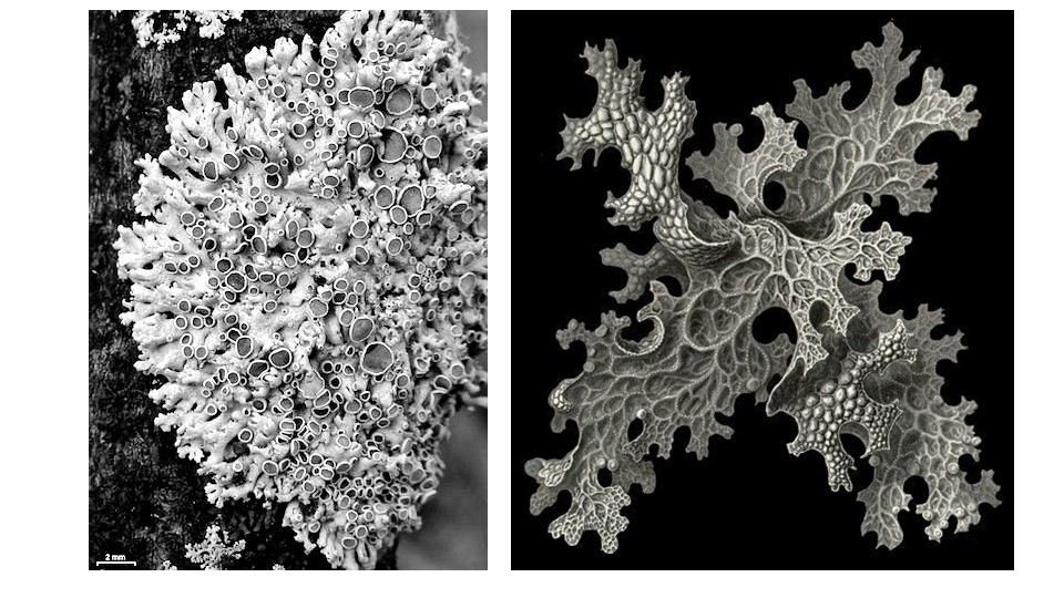
Figure 2: Moss growth pattern used as visual reference for the root growth design.
Using photographs and visual references of moss patterns, I brought the images into Photoshop and experimented with the posterize tool to simplify and abstract the organic forms into high-contrast shapes. This process allowed me to identify potential pathways and structures that could later guide the root growth.
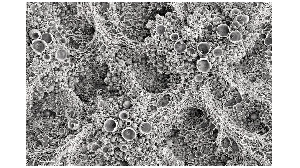
Figure 3: Photoshop posterization process applied to moss reference images to extract abstract growth patterns.
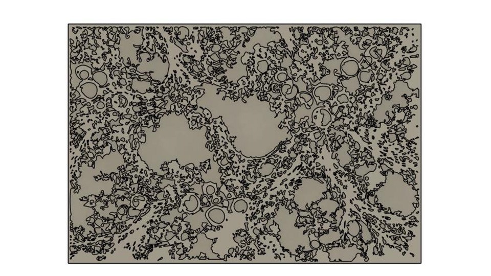
Figure 4: Further abstraction of moss patterns used to define root guidance channels.
After selecting a composition, I imported the abstracted pattern into Fusiion360, where I began modeling the geometry digitally. My initial idea was to create a three-dimensional mold through 3D printing and later cast the mold for root growth. However, during the development process, I realized that this approach would be difficult to execute because of the complexity of extraction and the unpredictable behavior of the roots inside enclosed volumes.
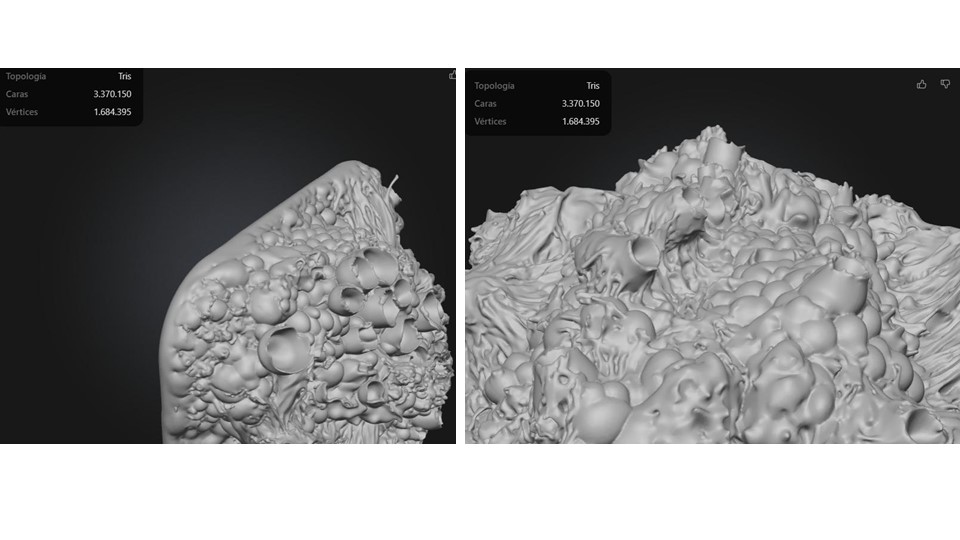
Figure 5: Digital modeling of the abstracted pattern in Rhino for mold development.
Texture Development Process
The texture was developed through an image-based workflow that translated a two-dimensional visual pattern into a three-dimensional surface. The process began with the selection of a high-contrast image containing an organic cellular structure. The image was edited in Adobe Photoshop and converted into a binary black-and-white composition using a threshold adjustment, allowing the differentiation between solid and void areas.
Once the desired contrast was achieved, the image was imported into Adobe Illustrator, where the Image Trace function was used to convert the raster image into vector geometry. The resulting paths were refined and simplified to obtain clean, continuous contours suitable for three-dimensional modeling.
The vectorized pattern was then exported as an SVG file and imported into Fusion 360 using the Insert SVG command. A rectangular base measuring 400 × 600 mm was created and extruded to generate the main volume. The imported pattern was positioned and scaled to fit the surface of the model.
Finally, the vector geometry was used to define the textured areas, which were transformed into relief through an Extrude Cut operation. This process produced a three-dimensional surface whose morphology directly originated from the visual characteristics of the source image, translating its organic structure into a manufacturable digital texture.
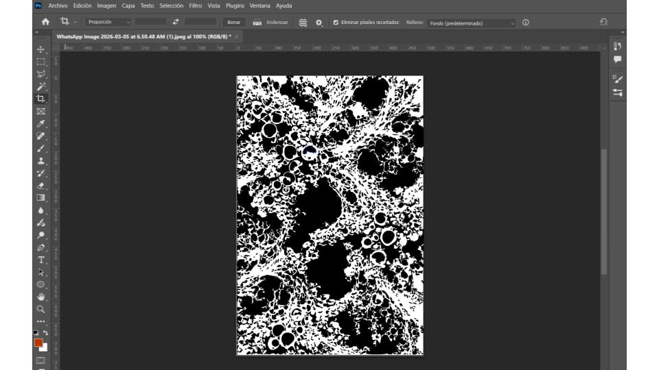
Figure 6: Image edited in Adobe Photoshop and converted into a binary black-and-white composition .
Because of this, I shifted the strategy toward a flat format that would allow the roots to grow more openly across the surface. I then redesigned the pattern thinking specifically about which areas would be perforated using the CNC router. This process helped define the channels, voids, and surfaces that would later guide the roots while maintaining the interconnected structure inspired by moss growth.
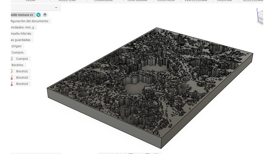
Figure 7: Redesigned flat pattern prepared for CNC routing, showing perforated channels and voids.
Later, I transferred the project to the CNC router for fabrication. The milling process took approximately 18 hours to complete on a 50 × 90 cm wooden piece with a depth of 1.5 cm. A 1/8-inch cutting tool was used at a low speed in order to prevent the bit from breaking during the long machining process.
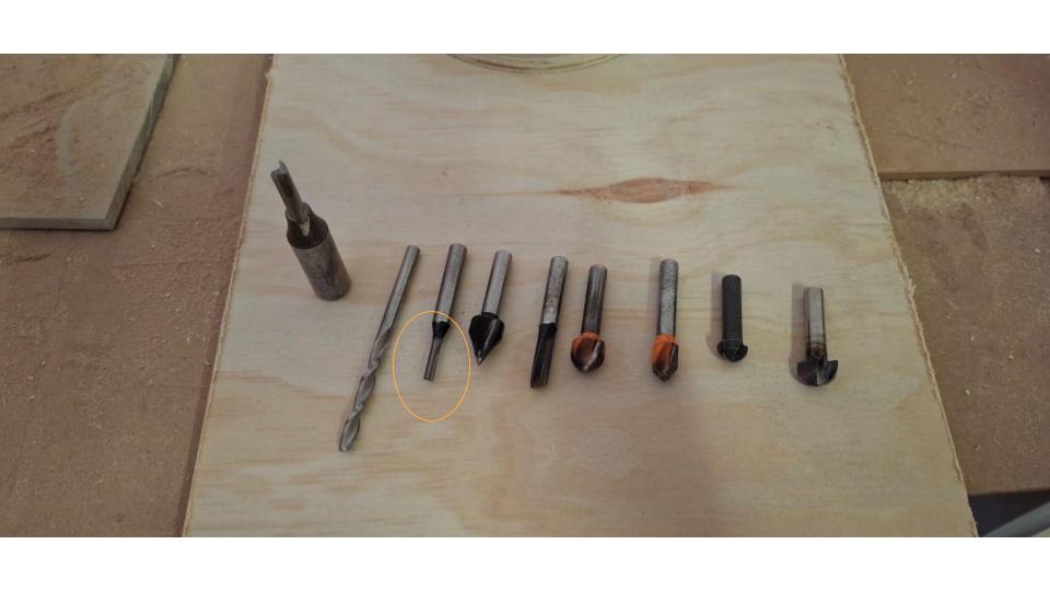
Figure 8: Cutting tools used during the CNC milling process.
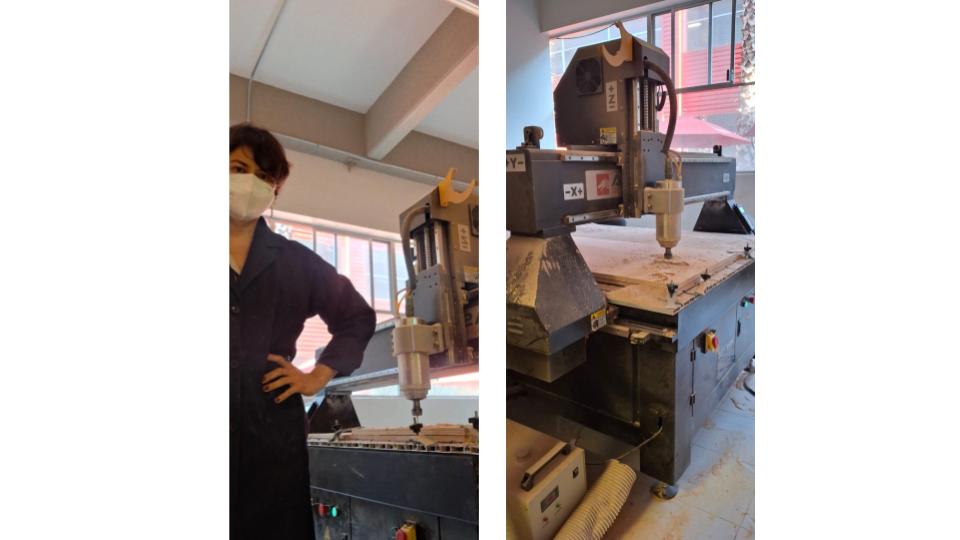
Figure 9: CNC router during the milling process of the wooden mold.
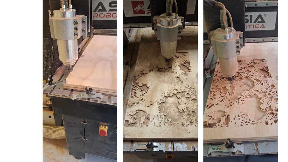
Figure 10: Completed CNC-milled wooden mold showing the moss-inspired pattern.
Once the milling was completed, the original plan was to thermoform a polypropylene mold using the wooden structure. To prepare the piece for vacuum forming, I perforated the surface to allow air to pass through and enable the vacuum system to function correctly during the thermoforming process. However, the thermoforming machine was not functioning properly and could not generate the necessary vacuum.
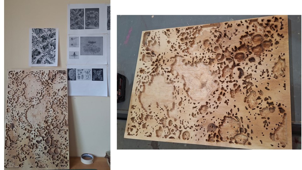
Figure 11: Perforated wooden mold prepared for vacuum forming process.
As a result, I decided to adapt the process and directly plant the seeds into the wooden mold itself. This unexpected shift in methodology transformed the piece from a fabrication intermediary into an active growth environment, reinforcing the project's exploration of living systems, adaptation, and relational processes.
However, my expectations quickly confronted the reality of working with living systems. Once the wooden mold containing the chia seeds was continuously humidified, fungi began to grow almost immediately, preventing the roots from developing properly. The moisture required for germination created an unstable environment where contamination spread faster than the roots themselves.
Faced with the need to continue advancing the project, I decided to shift the methodology and experiment with biomaterials that visually and structurally resembled root systems. This transition allowed me to maintain the conceptual focus on interconnected networks, organic growth, and relational structures, while adapting the material process to the practical limitations encountered during cultivation.
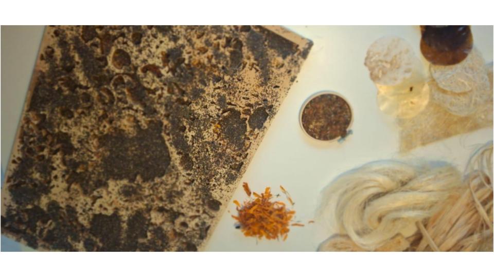
Figure 12: Fungal contamination developing in the humidified wooden mold with chia seeds.
To develop a biomaterial that visually resembled root systems, I experimented with the following formula: 350 ml of water, 72 g of gelatin, 120 g of plant waste, 250 ml of glycerin, and 70 ml of vinegar. During the process, I noticed that the material adhered successfully to the mold surface, creating an organic texture similar to intertwined roots. However, a single application was not enough to fully cover the structure, so I had to repeat the formula three times to build sufficient layers across the entire mold.
At the same time, I decided to experiment with marigold (cempasúchil) plant waste because of its intense yellow pigmentation and organic fiber qualities. My intention was to explore the possibility of producing a biotextile or bioleather alternative in case the primary mold process failed again. This experimentation allowed the project to remain adaptable, integrating material exploration and iterative making as part of the research process itself.
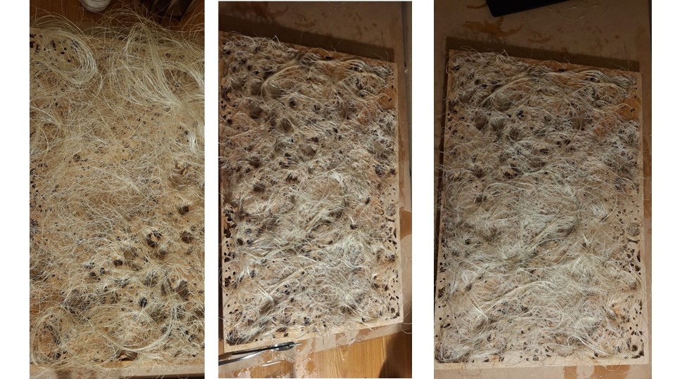
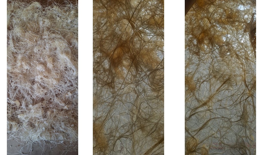
Figure 13 & 14: Shift toward biomaterials resembling root systems after cultivation setbacks.
The material experiments also involved testing different types of substrates, since having multiple material options for constructing the wearable piece became essential for integrating the electronic components into the garment. Each substrate responded differently in terms of flexibility, adhesion, texture, and structural resistance, which directly affected the possibility of embedding sensors, wiring, and interactive elements within the final piece.
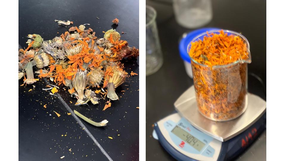
Figure 15: Unprocessed cempasúchil flowers prior to cleaning, followed by the weighing of a large quantity of petals for material preparation and experimental testing.
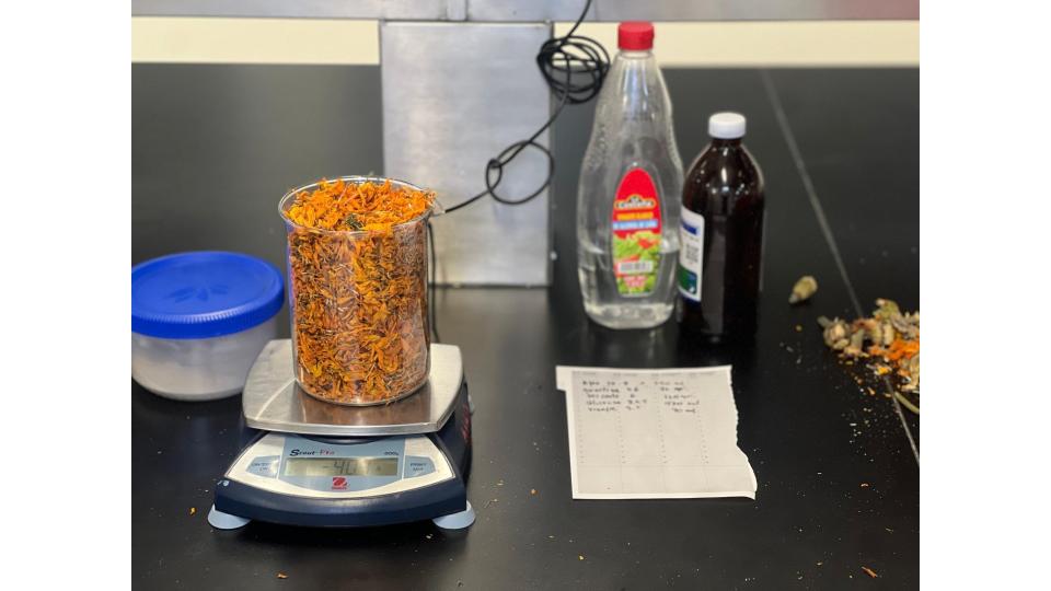
Figure 16: Materials used in the biomaterial formulation. From left to right: grenetin, a scale with cempasúchil flowers, glycerin, and vinegar..
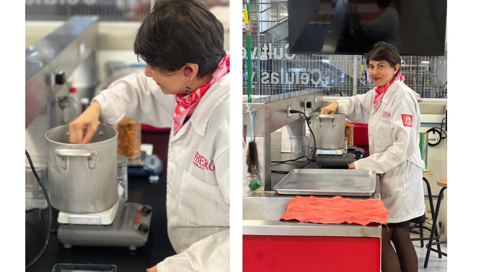
Figure 17: Heating process of the gelatin mixture while continuously monitoring the temperature to ensure it reaches 70°C before incorporating the remaining ingredients.
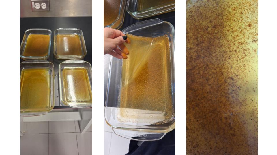 Figure 18: Gelatin-based biomaterial reinforced with cempasúchil petals during the fabrication process: placement of the mixture into the mold, demolding after curing, and the final piece exhibiting a translucent finish that highlights the embedded organic material.
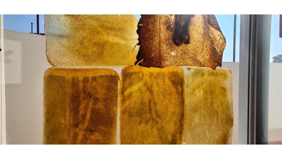 Figure 19: Gelatin-based biomaterial incorporating cempasúchil petals. The material exhibits translucent properties, allowing the petals to remain visible within the structure. This transparent finish was intentionally pursued to highlight the organic texture, color, and distribution of the flower fragments throughout the material.
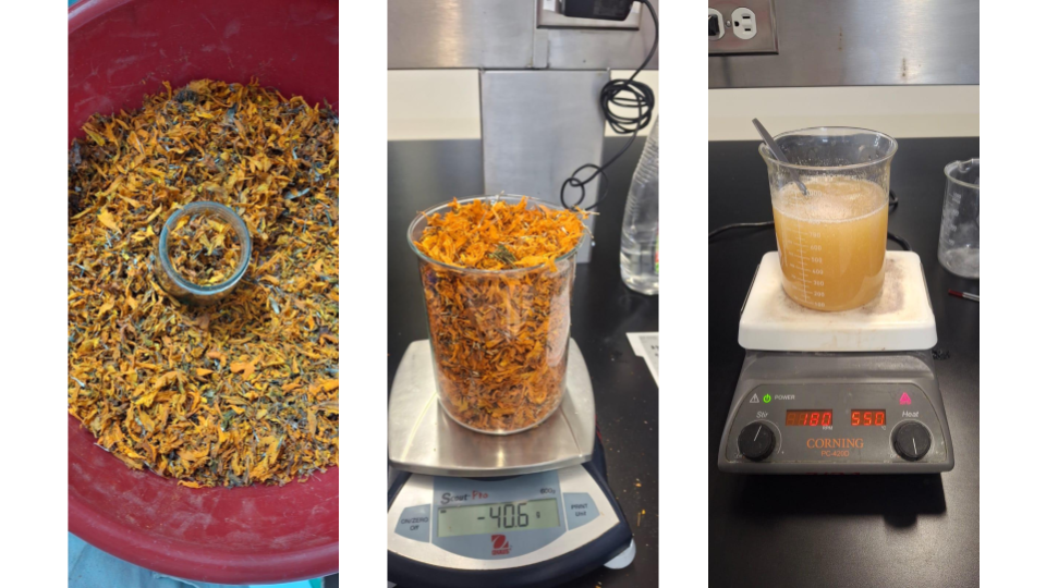
Figure 20:Formulation of the cempasúchil-based biomaterial used for the development of the wearable prototype .

Figure 21: The cempasúchil formulation emphasized translucency and the visibility of embedded organic matter .
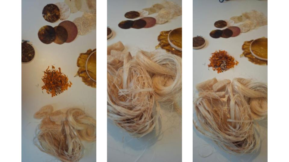
Figure 22: Material samples developed from cempasúchil flower petals and henequen fibers. The henequen-based biomaterial was explored to replicate the visual and tactile qualities of plant roots, while the cempasúchil formulation emphasized translucency and the visibility of embedded organic matter.
These tests became an important part of the development process, allowing the project to balance biological aesthetics, material behavior, and technological functionality while maintaining the conceptual focus on relationality and interconnected systems.
Recipes
| Ingredient | Amount |
|---|---|
| Water | 350 mL |
| Gelatin | 72 g |
| Cempasúchil flower waste | 120 g |
| Glycerin | 250 mL |
| Vinegar | 70 mL |
Table. Formulation of a cempasúchil (Tagetes erecta) flower-based biomaterial.
Electronic Design Process
The wearable integrates a TCS34725 RGB Color Recognition Sensor with three NeoPixel LEDs to establish a responsive relationship between the surrounding vegetation and the body. The TCS34725 continuously analyzes environmental color information, but the system is specifically programmed to isolate and interpret only green tonalities. By filtering the RGB values, the device becomes sensitive exclusively to the presence, intensity, and variation of greens found in plants, leaves, and organic environments.
As the sensor detects changes between darker, muted, or highly saturated greens, the microcontroller translates these readings into dynamic light responses through the three NeoPixels. Deep greens generate softer and more subtle illumination, while vivid greens activate brighter and more vibrant light emissions. This creates a continuous visual feedback system where the wearable reacts directly to the living environment around it.
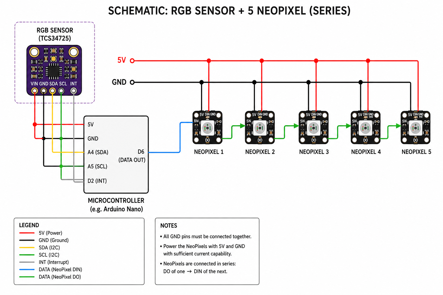
Figure 23: Schematic diagram of the breadboard prototype used to test the RGB sensor and NeoPixel color responses before integration into the wearable system.
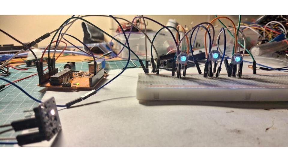
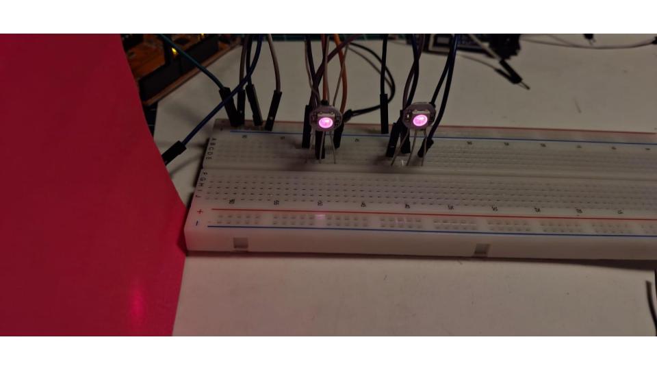
Figure 24: Breadboard prototyping and testing phase used to program and evaluate color responses. The circuit was configured to control the LEDs and explore different color outputs based on sensor inputs, allowing validation of the interaction logic before integrating the electronics into the wearable prototype.
Code
//  NeoPixel + Sensor de color TCS34725
//  El NeoPixel refleja el color detectado por el sensor
// ============================================================

#include <Wire.h>
#include "Adafruit_TCS34725.h"
#include <Adafruit_NeoPixel.h>

// --- Configuración de pines y LEDs ---
#define PIN_NEOPIXEL  6
#define NUM_PIXELS    1
#define BRILLO        150   // 0-255, baja si el LED es muy intenso

// --- Sensor: tiempo de integración largo + ganancia alta para más precisión ---
Adafruit_TCS34725 tcs = Adafruit_TCS34725(
  TCS34725_INTEGRATIONTIME_154MS,  // 154ms es buen balance velocidad/precisión
  TCS34725_GAIN_4X                 // Ajusta según la luz del entorno
);

Adafruit_NeoPixel strip(NUM_PIXELS, PIN_NEOPIXEL, NEO_GRB + NEO_KHZ800);

// --- Parámetros de corrección de color ---
#define UMBRAL_LUZ_MINIMA  20    // Valor mínimo de C para considerar lectura válida
#define GAMMA             1.8    // Corrección gamma (1.0 = sin corrección)

// --- Prototipo de funciones ---
uint8_t corregirGamma(uint8_t valor);
uint32_t leerColorSensor();
void testNeopixel();
void mostrarError();


// ============================================================
void setup() {
  Serial.begin(9600);
  Serial.println("=== NeoPixel + TCS34725 ===");


  // Iniciar NeoPixel
  strip.begin();
  strip.setBrightness(BRILLO);
  strip.clear();
  strip.show();

  // Test de colores al arrancar
  testNeopixel();

  // Iniciar sensor
  if (!tcs.begin()) {
    Serial.println("ERROR: Sensor TCS34725 no encontrado.");
    Serial.println("Verifica conexiones SDA/SCL y alimentacion.");
    mostrarError();   // parpadeo rojo infinito
  }

  // Apagar LED integrado del sensor para no afectar lecturas
  tcs.setInterrupt(true);

  Serial.println("Sensor OK. Leyendo colores...");
  Serial.println("R\tG\tB\tC\t| rN\tgN\tbN");
}

// ============================================================
void loop() {
  uint16_t r, g, b, c;
  tcs.getRawData(&r, &g, &b, &c);

  // Imprimir valores crudos en Serial Plotter / Monitor
  Serial.print(r); Serial.print("\t");
  Serial.print(g); Serial.print("\t");
  Serial.print(b); Serial.print("\t");
  Serial.print(c); Serial.print("\t| ");

  if (c < UMBRAL_LUZ_MINIMA) {
    // Sin luz suficiente: apagar el pixel
    strip.setPixelColor(0, strip.Color(0, 0, 0));
    strip.show();
    Serial.println("--- sin luz ---");

  } else {
    // Normalizar a 0-255 usando el canal Clear como referencia
    // Limitar a c para evitar desbordamiento si R+G+B > C
    uint8_t rN = constrain(map(r, 0, c, 0, 255), 0, 255);
    uint8_t gN = constrain(map(g, 0, c, 0, 255), 0, 255);
    uint8_t bN = constrain(map(b, 0, c, 0, 255), 0, 255);

    // Corrección gamma para colores más naturales
    uint8_t rG = corregirGamma(rN);
    uint8_t gG = corregirGamma(gN);
    uint8_t bG = corregirGamma(bN);

    strip.setPixelColor(0, strip.Color(rG, gG, bG));
    strip.show();

    Serial.print(rG); Serial.print("\t");
    Serial.print(gG); Serial.print("\t");
    Serial.println(bG);
  }

  // El delay debe ser mayor que el tiempo de integración del sensor
  delay(200);
}

// ============================================================
// Corrección gamma para que los colores se vean más naturales
// ============================================================
uint8_t corregirGamma(uint8_t valor) {
  float v = valor / 255.0;
  v = pow(v, 1.0 / GAMMA);
  return (uint8_t)(v * 255.0);
}

// ============================================================
// Test visual: rojo → verde → azul → blanco → apagado
// ============================================================
void testNeopixel() {
  const uint32_t colores[] = {
    strip.Color(255, 0,   0  ),   // Rojo
    strip.Color(0,   255, 0  ),   // Verde
    strip.Color(0,   0,   255),   // Azul
    strip.Color(255, 255, 255),   // Blanco
  };
  const char* nombres[] = { "Rojo", "Verde", "Azul", "Blanco" };

  Serial.println("Test NeoPixel...");
  for (int i = 0; i < 4; i++) {
    Serial.print("  -> "); Serial.println(nombres[i]);
    strip.setPixelColor(0, colores[i]);
    strip.show();
    delay(400);
  }
  strip.clear();
  strip.show();
  Serial.println("Test OK");
}

// ============================================================
// Parpadeo rojo de error (se queda aquí si el sensor falla)
// ============================================================
void mostrarError() {
  while (true) {
    strip.setPixelColor(0, strip.Color(255, 0, 0));
    strip.show();
    delay(200);
    strip.clear();
    strip.show();
    delay(200);
  }
}
The NeoPixels are distributed across the structure like small luminous organisms embedded within the biomaterial surface. Their transitions are programmed using gradual fading and smooth interpolation so the color changes appear fluid and organic rather than mechanical. The result is a slow pulsation of green light that mirrors the rhythms and variations of plant life.
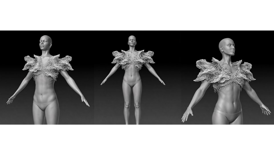
Figure 25: First wearable proposal developed using biomaterials inspired by root structures. While the concept successfully conveyed an organic aesthetic, the surface exhibited excessive texture, making it difficult to achieve the desired level of refinement and integration with the body.
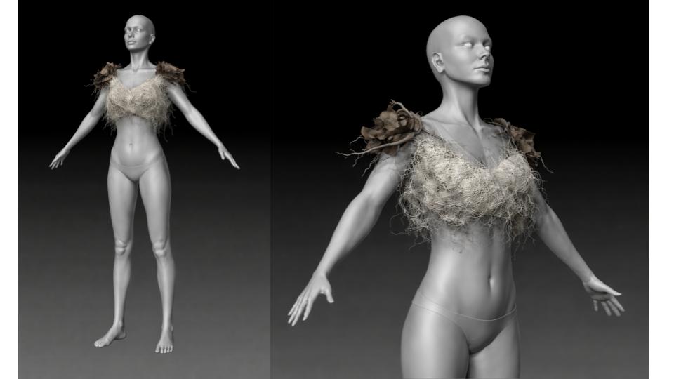
Figure 26: Second wearable proposal developed after evaluating the limitations of the initial prototype. This iteration refined the form, material distribution, and surface quality, achieving a closer integration between the biomaterial components, electronic elements, and the intended root-inspired aesthetic..
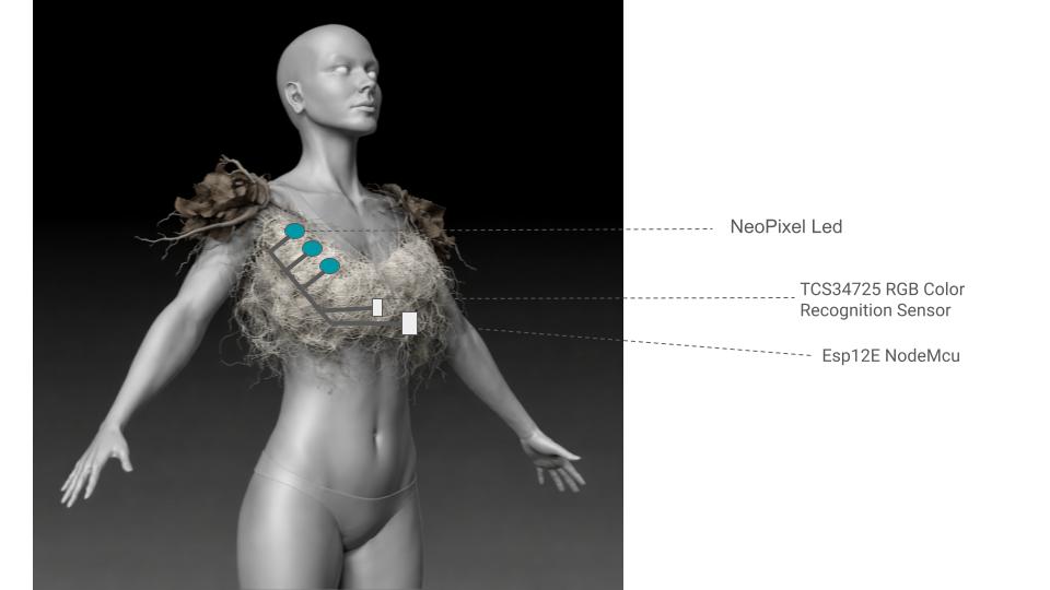
Figure 27: Proposed integration of the electronic system within the wearable structure. The design explores the placement of sensors, microcontroller, LEDs, and conductive connections within the biomaterial components, seeking a seamless relationship between technology, the body, and the organic forms inspired by plant root systems.
Through this interaction, the wearable transforms environmental color into a sensory language. Instead of presenting technological data in numerical form, the system allows users to experience vegetation through light, movement, and atmosphere, reinforcing the project’s exploration of ecological connection, responsive biomaterials, and embodied interaction between technology and nature.
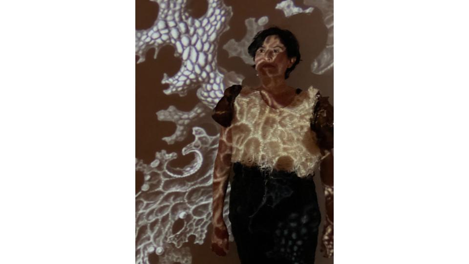
Photoshoot
Photoshoot of the final wearable proposal, documenting the integration of biomaterials, electronic components, and root-inspired forms on the body. The photographic session highlights the relationship between technology, nature, and human perception envisioned through the project.
Fabrication Files
FILE MOLD RHINO
FILE ARDUINO
* FILE PDF - ARDUINO SENSOR COLOR * * FILE PDF - ARDUINO SENSOR COLOR GREEN *