9. Wearables

Research
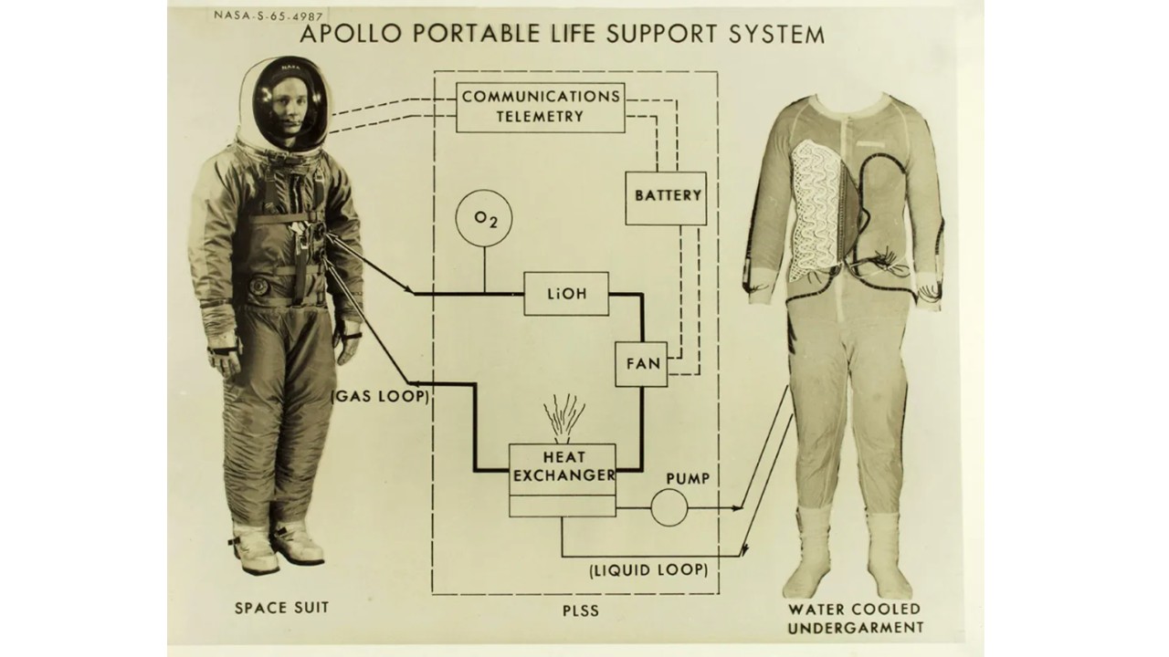 Figure 1: Apollo portable life support system, 1965, diagram from NASA
Wearable technology has evolved from science fiction into an essential part of daily life, with applications ranging from activity trackers to smart clothing and augmented reality. In the space context, this evolution is reflected in the development of advanced suits like those of the Artemis mission and devices designed to monitor astronauts' health in real-time. Just as wearables facilitate remote monitoring and personalized healthcare on Earth, they help track vital signs in space to understand the effects of the space environment on the human body. However, challenges such as battery life and data security arise in both contexts, highlighting the need for continuous innovation to maximize their impact on space exploration and everyday life.
References & Inspiration
Jenny Tillotson
Scentsory Design® is an innovative concept that merges emerging technology with traditional perfumery to create garments and accessories capable of releasing fragrances in response to emotional or environmental stimuli. This approach, developed by Jenny Tillotson, integrates wireless sensors and microfluidic devices into smart textiles, providing psychological and therapeutic benefits to users.
Inspired by the human nervous system and the defense mechanisms of certain insects, such as the bombardier beetle, Scentsory Design® generates a personalized "scent bubble" around the wearer. This controlled release of beneficial aromas adapts to individual needs, enhancing well-being and reducing stress.
Additionally, Scentsory Design® explores applications beyond personal scent diffusion. The concept includes fragrance-free zones, where garments communicate the user's sensitivity to specific scents, as well as dynamic fragrance adjustments based on music or social environments. These innovations offer a unique and customizable olfactory experience.
By fusing fashion with olfactory science, Scentsory Design® represents a pioneering step toward enhancing mental health and emotional well-being through multisensory interaction.
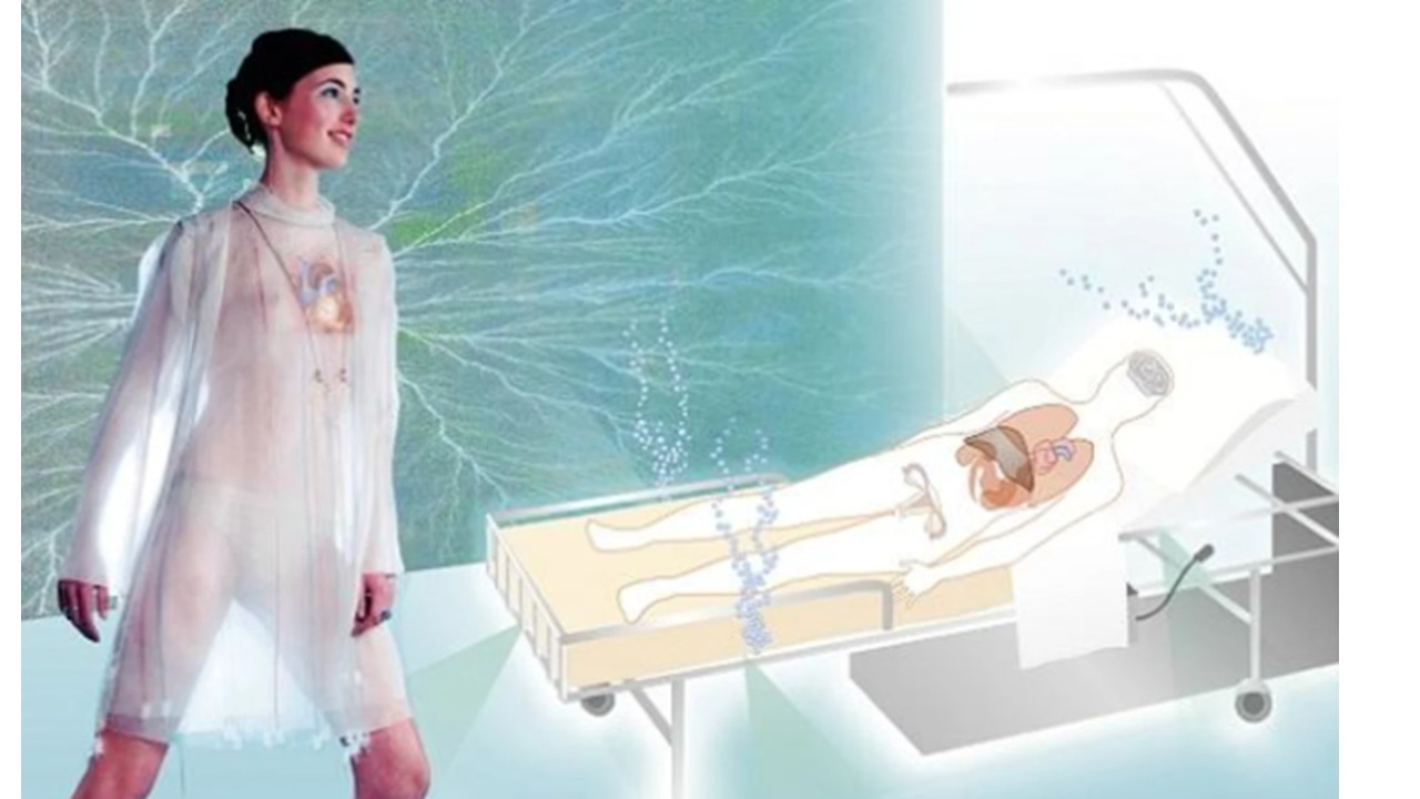
Figure 2: Tillotson, J. (2006). Scentsory design: The emotional living tissue. In The Future of the 20th Century: Collecting, Interpreting and Conserving Modern Materials. Archetype Publications.
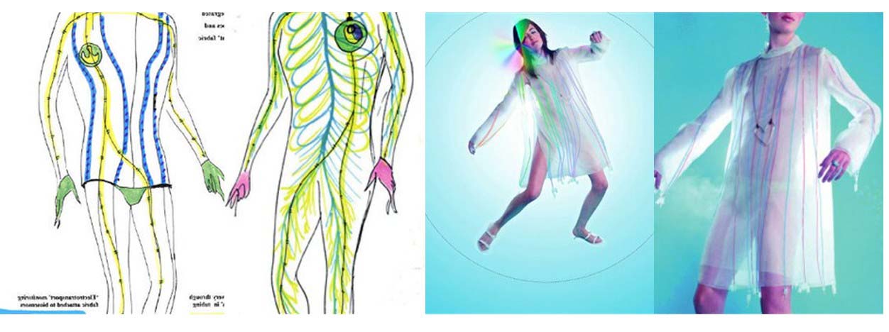 Figure 3: Tillotson, J. (2006). Scentsory design: The emotional living tissue. In The Future of the 20th Century: Collecting, Interpreting and Conserving Modern Materials. Archetype Publications.
Susanna Hertrich
Prosthesis for a Lost Instinct is a project by Susanna Hertrich that explores the possibility of restoring instinctive responses lost in modern humans. Developed during her thesis at the Royal College of Art's Design Interactions Department, the project examines how technological interventions can reintroduce natural warning signals that have diminished due to societal and environmental changes.
The core idea behind Prosthesis for a Lost Instinct is to create a device that mimics the physiological response of goosebumps and heightened alertness. By stimulating the skin with microelectric currents, the prosthesis triggers sensations associated with primal fear and readiness, helping the wearer develop a stronger awareness of real dangers rather than exaggerated media-driven anxieties.
This speculative design challenges perceptions of risk and human adaptation, questioning whether technology could not only augment but also restore biological functions that have become less prominent in contemporary life.
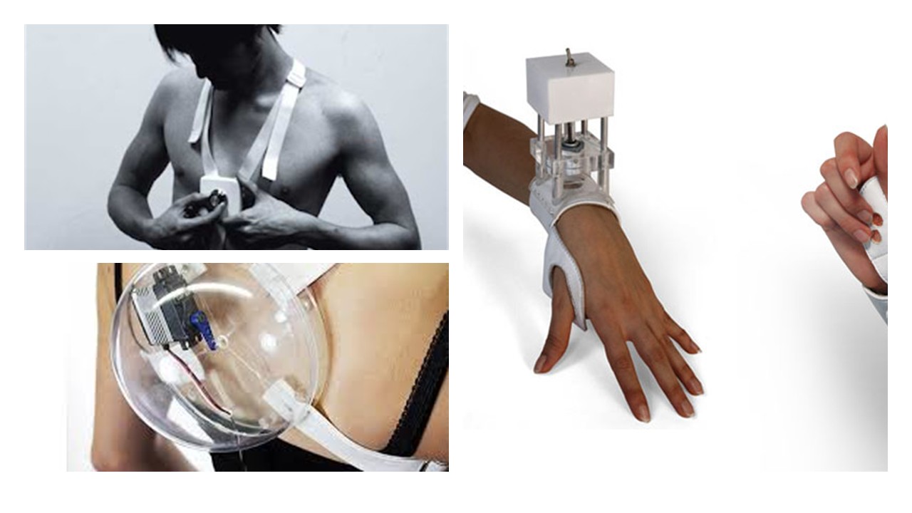 Figure 3: Hertrich, S. (n.d.). Susanna Hertrich. Retrieved from Susanna Hertrich
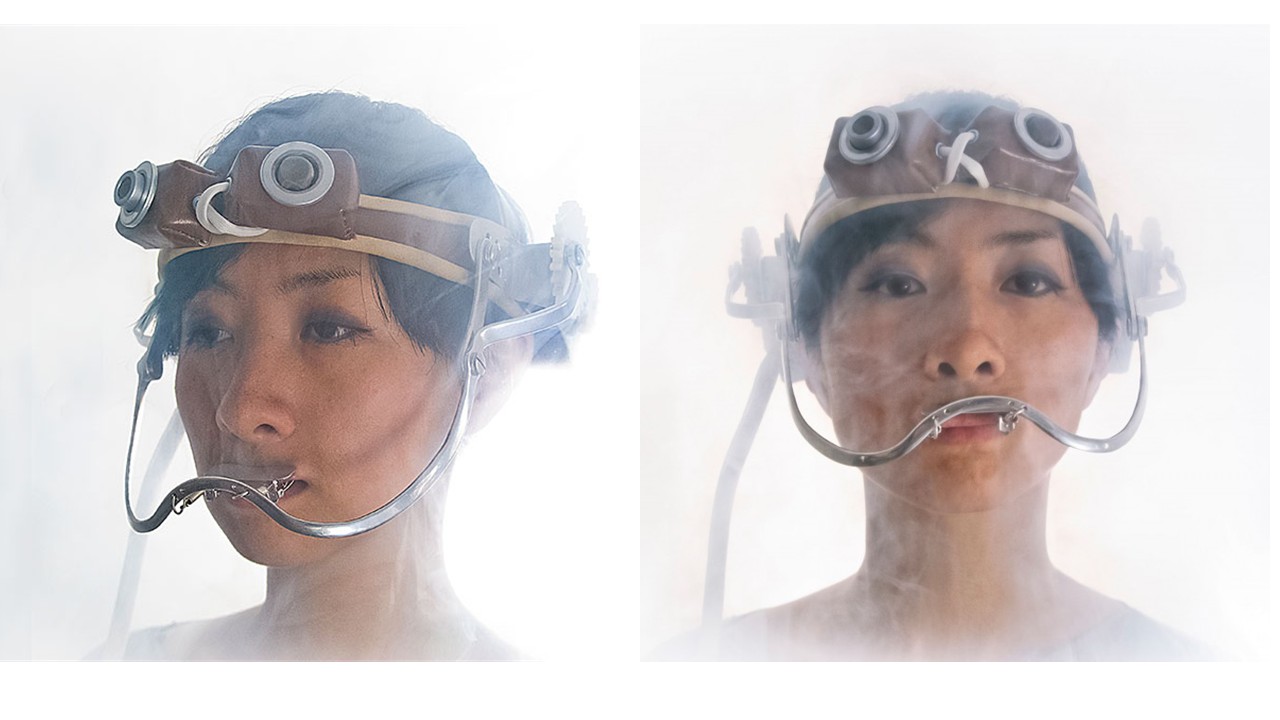 Figure 4: Hertrich, S. (n.d.). Susanna Hertrich. Retrieved from Susanna Hertrich
References
Process and Workflow
I used a buzzer and an LDR (light-dependent resistor) to create a simple version of a theremin. A theremin is a musical instrument known for being one of the only instruments in the world that can be played without physical contact. Instead of touching it, the performer controls sound through changes in proximity. In my case, I simulated this behavior by taking advantage of how an LDR works. The LDR changes its electrical resistance depending on the amount of light it receives. By varying the light—using a hand to block or expose the sensor—I was able to modify the signal sent to the buzzer.
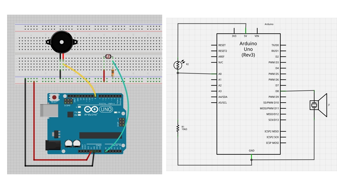 Figure 5: Prototype and schematic of an Arduino-based LDR sensor with buzzer. Author’s own work.
As a result, the pitch or tone produced by the buzzer changes continuously based on light intensity, allowing me to “play” the instrument without touching it, similar to how a traditional theremin responds to hand movement in space.
Code Example 1: LDR Sensor with Buzzer
#define PIN_LDR A0
#define TIEMPO_ESPERA 1000
#define buzzer 5

int b1 = 0;
int b2 = 0;
int b3 = 0;
int b4 = 0;
int b5 = 0;

void setup() {
  Serial.begin(9600);
  pinMode(buzzer, OUTPUT);
}

void loop() {
  int iValorLDR = analogRead(PIN_LDR);
  Serial.println(iValorLDR);
  delay(TIEMPO_ESPERA);

  if (b1 == 1) tone(buzzer, 200, 100);
  if (b2 == 1) tone(buzzer, 400, 100);
  if (b3 == 1) tone(buzzer, 500, 100);
  if (b4 == 1) tone(buzzer, 600, 100);
  if (b5 == 1) tone(buzzer, 700, 100);

  delay(10);
}
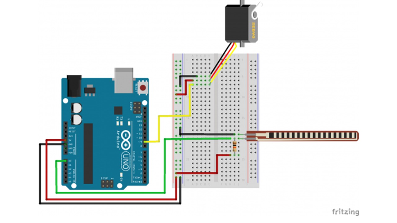 Figure 6: Prototype of an Arduino-based Servo motor controlled via analog input from a sensor.Author’s own work.
Code Example 2: Servo with Analog Sensor
#include <Servo.h>

Servo myservo;

int potpin = A0;
int ResRead;

void setup() {
  myservo.attach(9);
  Serial.begin(9600);
}

void loop() {
  ResRead = analogRead(potpin);
  Serial.print("Lectura Analogica = ");
  Serial.println(ResRead);
  int val = map(ResRead, 400, 900, 0, 180);
  myservo.write(val);
  delay(150);
}
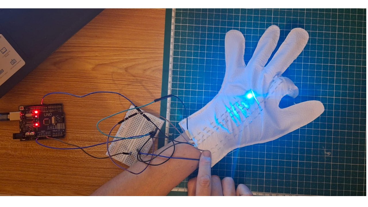
I integrated the Velostat into a flexible setup so that it responds to the bending of a finger. When the finger bends, the pressure on the material increases, which alters its resistance. This change is read by the microcontroller and translated into an input signal.
Based on this pressure variation, I programmed a NeoPixel LED to turn on and off. In this way, the intensity of the bend (and therefore the pressure) directly controls the behavior of the light, creating an interactive and responsive wearable system.
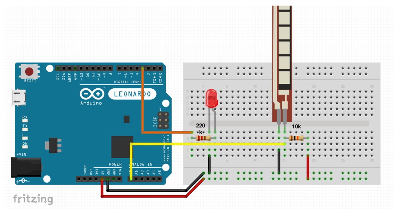 Figure 7: Prototype of an Arduino-based Flex sensor controlling an LED.Author’s own work.
Code Example 3: Flex Sensor with LED
const int flexPin = A0;
const int ledPin = 9;
int flexThreshold = 600;

void setup() {
  pinMode(ledPin, OUTPUT);
  Serial.begin(9600);
}

void loop() {
  int flexValue = analogRead(flexPin);
  Serial.println(flexValue);

  if (flexValue > flexThreshold) {
    digitalWrite(ledPin, HIGH);
  } else {
    digitalWrite(ledPin, LOW);
  }

  delay(100);
}

<iframe src="https://player.vimeo.com/video/1069833513?badge=0&autopause=0&player_id=0&app_id=58479" frameborder="0" allow="autoplay; fullscreen; picture-in-picture; clipboard-write; encrypted-media" style="width:100%; height:400px;" title="wearable 3"></iframe>
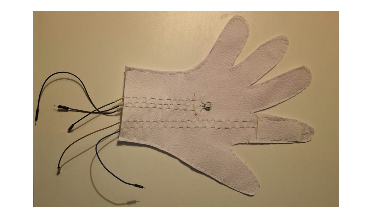
Components for the Textile Wearable Prototype
- 3 LEDs connected in series
- 1 Push button switch
- Conductive thread
- Coin cell battery (or portable power source)
- Textile substrate (fabric)
- Sewing needle
- Conductive stitching traces
- Insulating fabric or backing material (optional, for protection and durability)
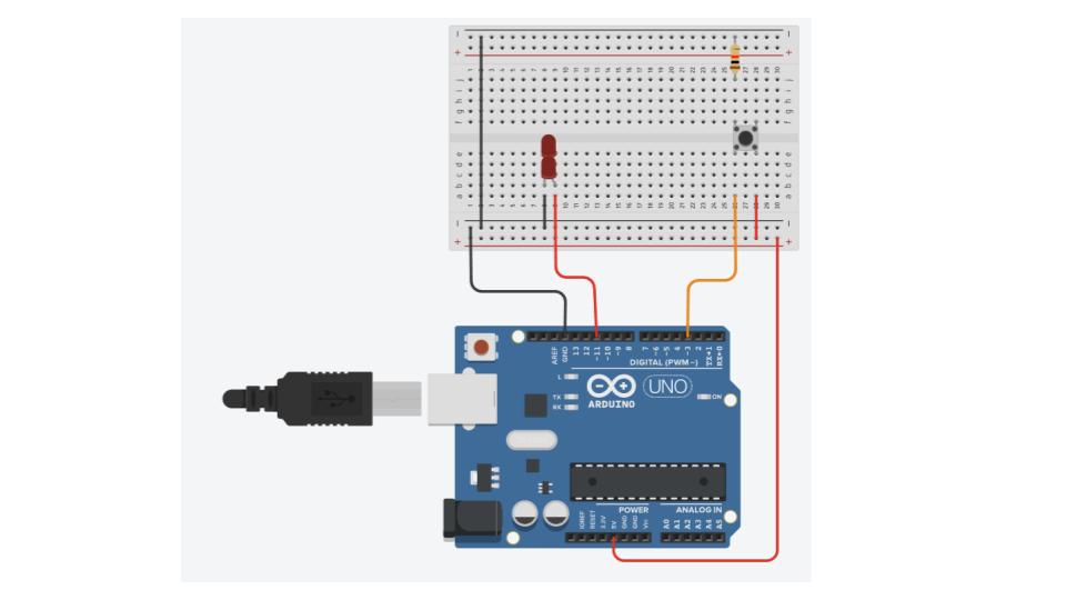
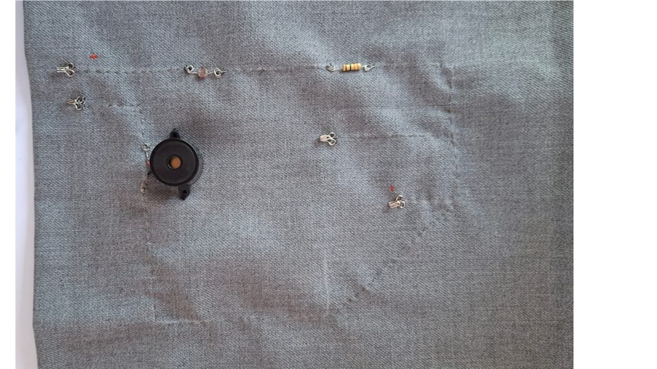
Figure 8: Prototype of an Arduino-based with 3 leds and button .Author's own work.
The wearable prototype was constructed using three LEDs connected in series, a push button for user interaction, and conductive thread to create the electrical connections directly on the textile surface. These components were integrated into the fabric to evaluate the feasibility of embedding electronic circuits into wearable structures while maintaining flexibility and comfort.
Code Example 4: Pressure Sensor with NeoPixel
#include <Adafruit_NeoPixel.h>

#define SENSOR_PIN A0
#define PIXEL_PIN 6
#define NUM_PIXELS 1

Adafruit_NeoPixel pixels(NUM_PIXELS, PIXEL_PIN, NEO_GRB + NEO_KHZ800);

int pressureValue = 0;
int threshold = 600;

void setup() {
  pixels.begin();
  pixels.clear();
  pixels.show();
  Serial.begin(9600);
}

void loop() {
  pressureValue = analogRead(SENSOR_PIN);
  Serial.println(pressureValue);

  if (pressureValue > threshold) {
    pixels.setPixelColor(0, pixels.Color(255, 0, 255));  // Magenta
  } else if (pressureValue > 100) {
    pixels.setPixelColor(0, pixels.Color(0, 255, 255));  // Cyan
  } else {
    pixels.setPixelColor(0, 0);  // Off
  }

  pixels.show();
  delay(100);
}
Results
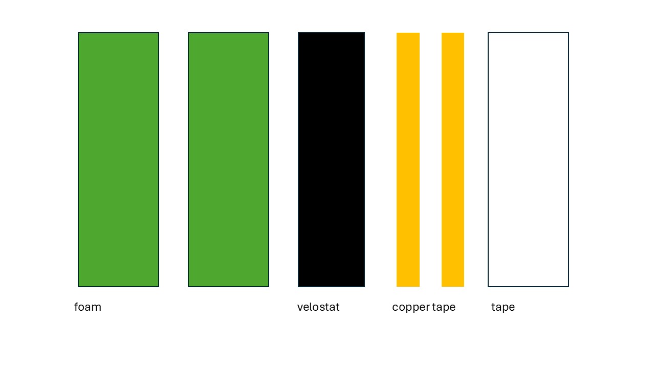
How to Build Your Own Flex Sensor
Materials Needed
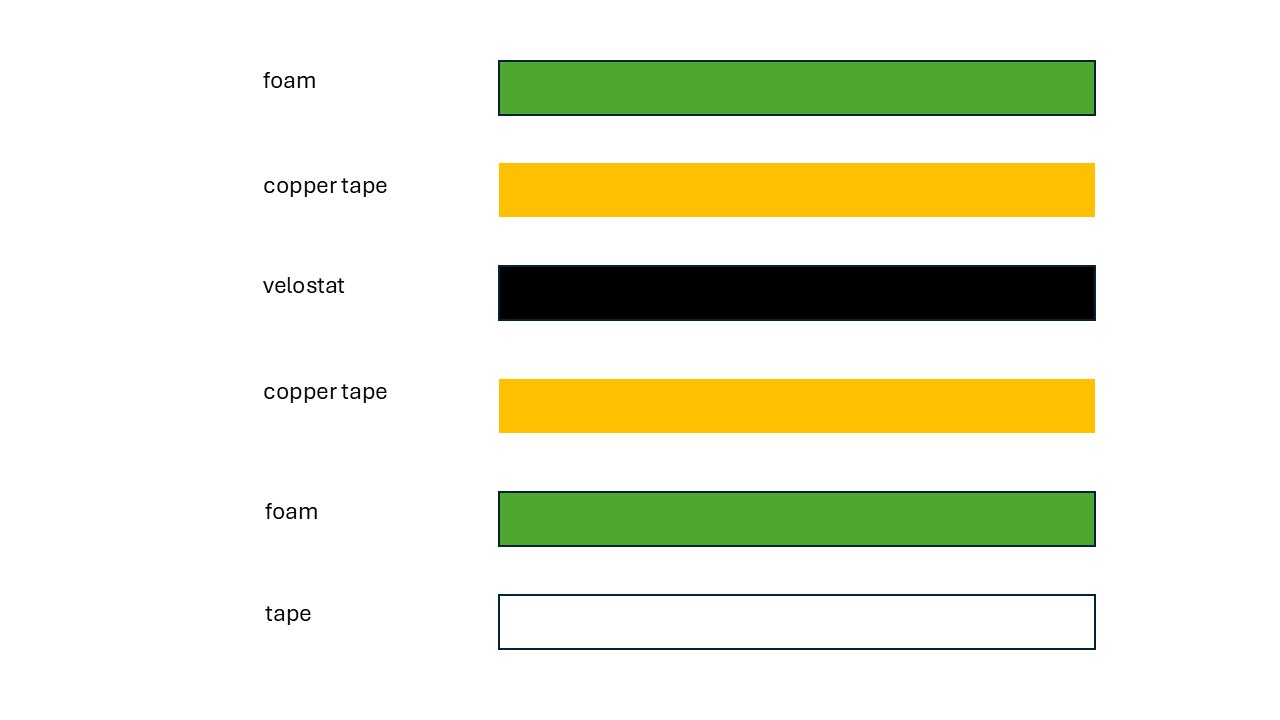
- Velostat
- Copper tape
- Foam
- Soldering kit
- Silicone wire (thin threaded wire is also fine)
- Tape
Step 1
Solder the wire to the copper tape.
Step 2
Place the velostat over the top of one of the copper strips, ensuring no copper or wire is covered by it.
Step 3
Sandwich the velostat between the two copper strips, as shown in the image below.