10. Textile Scaffold

Research
References & Inspiration
Carole Collet is a French-British designer and pioneer in biodesign and sustainability. She is a professor at Central Saint Martins, where she leads Maison/0 with LVMH and co-directs the Design & Living Systems Lab. Collet founded the Master's in Biodesign and the Material Futures program. Her research merges biology and design to create regenerative materials. Her notable project Biolace imagines plants producing both food and textiles. She promotes a design approach that collaborates with nature for a sustainable future.
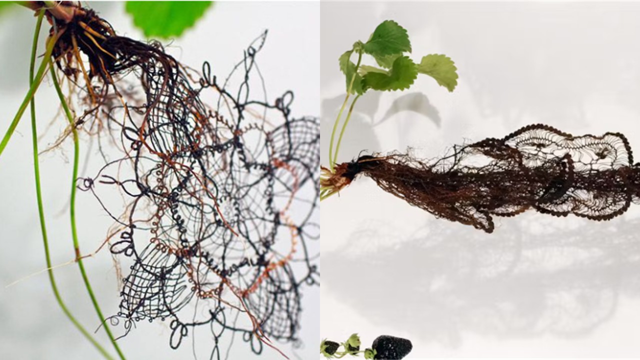
Figure 1: Collet, C. (n.d.). Carole Collet. Retrieved from Carole Collet
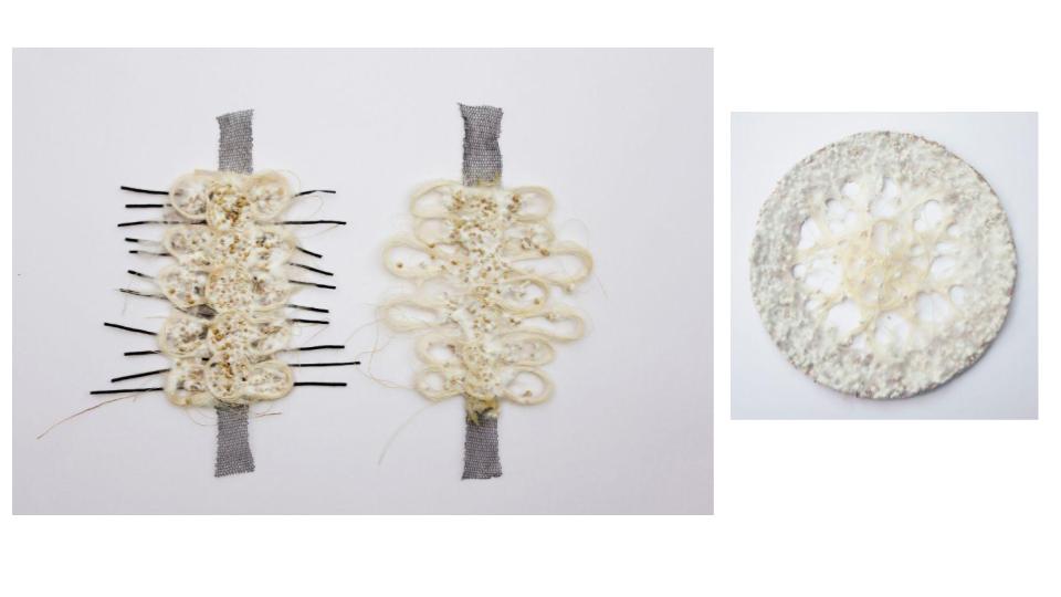
Figure 2: Collet, C. (n.d.). Carole Collet. Retrieved from Carole Collet
Maria Blaisse is a Dutch artist and designer born in 1944, known for her interdisciplinary work combining textile design, sculpture, and performance. She studied at the Gerrit Rietveld Academie and explored flexible materials and geometric forms, such as the toroid. Her work, characterized by the interplay between form, movement, and material, has been exhibited internationally and received several awards. She published The Emergence of Form, a retrospective of her career.
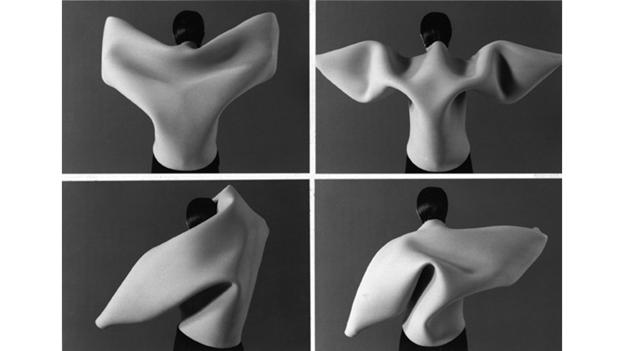
Figure 3: Blaisse, M. (1994). Moving back [Research, video]. Retrieved from Maria Blaisse
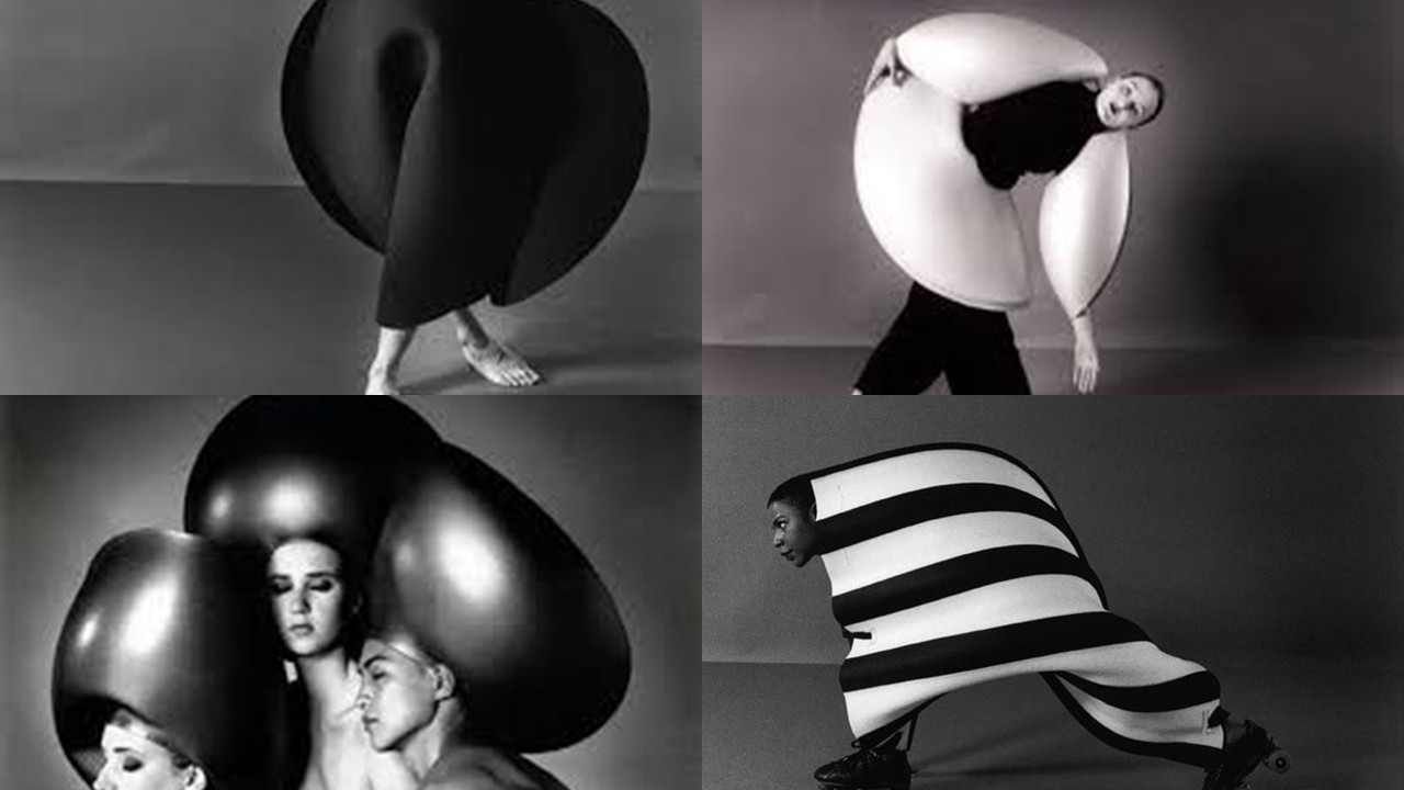
Figure 4: Blaisse, M. (1994). Moving back [Research, video]. Retrieved from Maria Blaisse
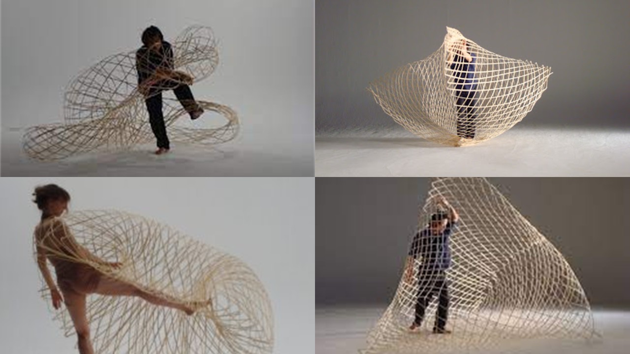
Figure 5: Blaisse, M. (2008). Bamboo explorations. Research project. Retrieved from Maria Blaisse
References
Tutorial: Living Surfaces Inspired by Hylozoic Ground (Philip Beesley) Using Laser Cut and Borax Crystallization
Concept
This project explores the relationship between the artificial and the organic, inspired by the work of architect and artist Philip Beesley, particularly his installation Hylozoic Ground. Through a series of biomorphic patterns designed in Illustrator, the goal is to create surfaces that appear sensitive, alive, or reactive. These pieces were laser-cut from white synthetic leather (cuerina) and later treated with borax crystallization, seeking an aesthetic that evokes natural or mineral growth on artificial structures.
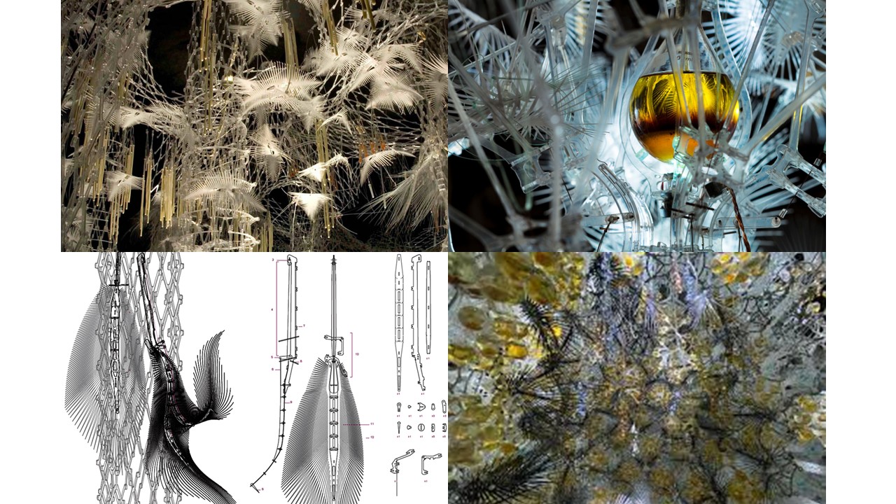
Figure 6: Beesley, P. (2025). Aria: Sentient Constellation. TU Delft Science Center, Delft, NL. Retrieved from https://www.philipbeesleystudioinc.com/sculptures/
Materials
- Adobe Illustrator software
- White synthetic leather (thin or medium thickness works best)
- Laser cutter
- Borax powder (30 g per 250 ml of water)
- Heat-resistant glass container
- Hot water (80–90 °C / 176–194 °F)
- String, clips, or suspension frame
- Safety gloves and goggles
- Paper towel or tray for drying
Design in Illustrator
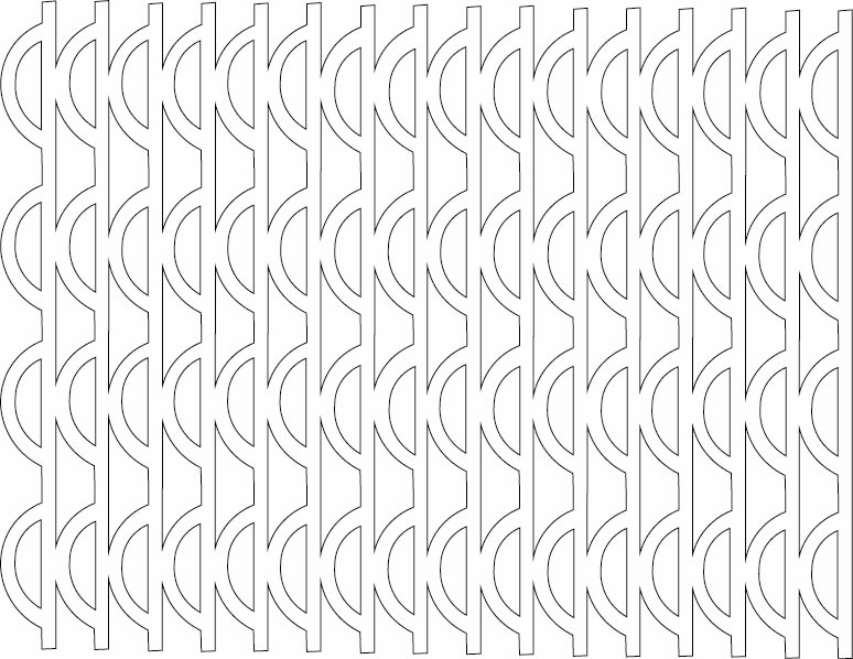
I started by opening Adobe Illustrator and creating a new document in A4 size or adjusted to match the dimensions of the laser cutter bed. From there, I developed cellular and branching patterns inspired by the work of Philip Beesley, focusing on organic, flexible structures that could later translate well into fabrication. To build these forms, I used tools like the Blend Tool to create smooth transitions and gradients, combined Rotate and Copy to generate radial repetitions, and applied Pathfinder (Minus Front) to carve out porous geometries.
As I refined the design, I made sure that all paths were properly closed and converted any strokes into outlines using Object > Path > Outline Stroke, ensuring compatibility with the laser cutting process. Once everything was ready, I saved the file in a format compatible with the fabrication workflow, typically .SVG or .AI, depending on the software used for the laser cutter.
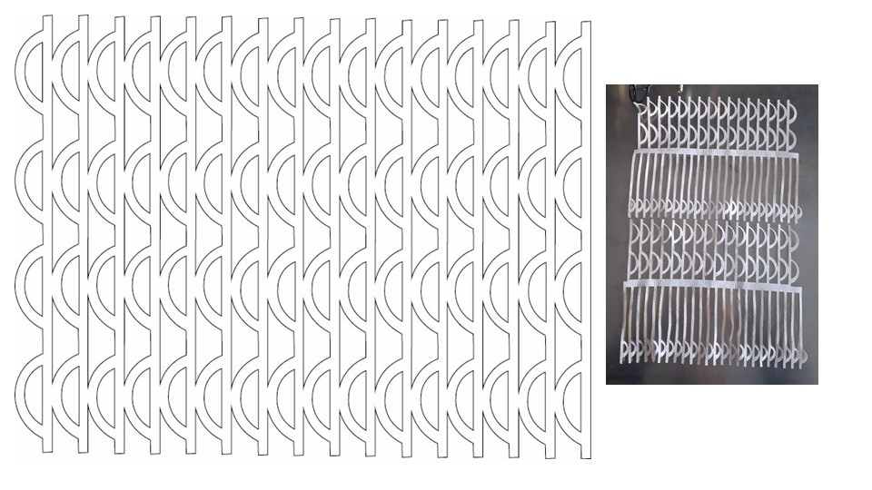
Laser Cut the White Synthetic Leather
I placed the synthetic leather flat on the laser bed and made sure it was firmly secured so it wouldn't shift during cutting. Then I set the laser parameters, keeping the speed at a medium level and adjusting the power between low and medium depending on the thickness of the material, while using a standard frequency suitable for synthetic surfaces. Before running the full job, I always did a small test cut to check how the material was responding and whether the settings needed adjustment. Once everything looked correct, I proceeded with the full cut and carefully removed the pieces afterward, using tweezers when necessary to avoid damaging the edges.
Prepare the Borax Solution
Materials Needed
- 30 g borax powder (decahydrate, formula: Na₂B₄O₇·10H₂O)
- 250 ml hot water (approx. 80–90 °C / 176–194 °F)
- Glass container (jar or heat-resistant cup)
- Cotton string (or a pipe cleaner to create a shape)
- Wooden stick or pencil (to suspend the string)
- Spoon for stirring
- Paper towel (for drying)
- Optional but recommended: gloves and safety goggles
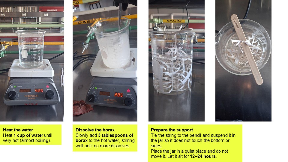
I started by heating about 250 ml of water until it was close to boiling, around 80–90 °C, making sure it was hot enough to dissolve the material properly. Then I poured the water into a glass container and gradually added 30 g of borax, stirring continuously until the solution reached saturation and no more borax would dissolve.
Suspend the Cut Pieces
I placed the laser-cut synthetic leather pieces into the solution using string or clips, making sure they were fully submerged but not touching the walls or bottom of the container. I left them hanging freely so the treatment could be evenly distributed across the surface. Then I allowed them to sit undisturbed for 12 to 24 hours, ensuring consistent exposure throughout the process.
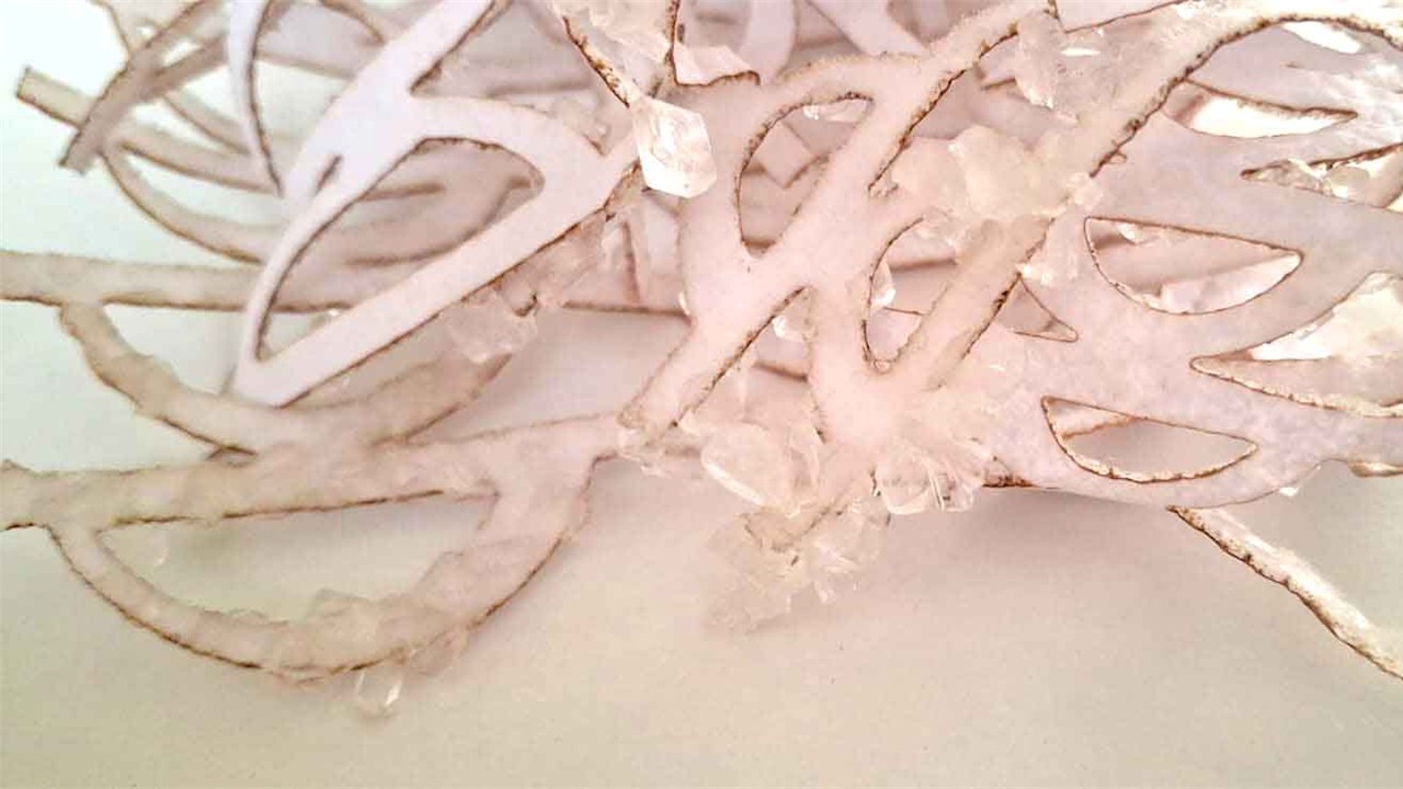
Drying and Results
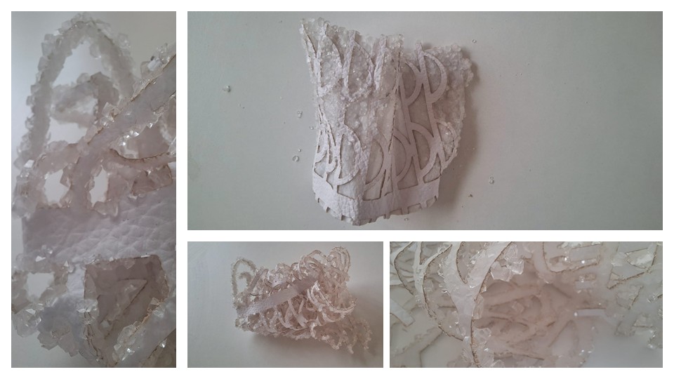
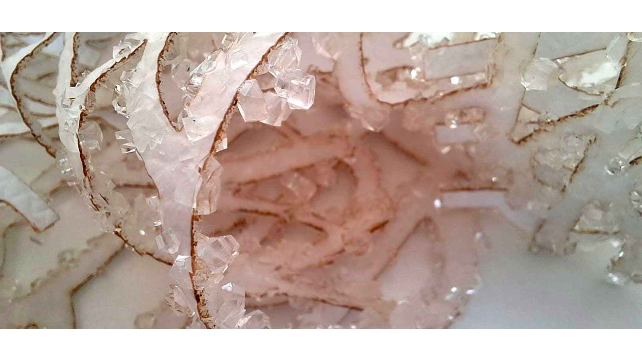
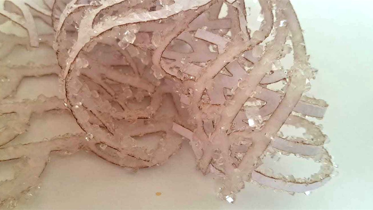
After the crystallization process, I carefully removed the pieces from the solution, making sure not to damage the newly formed structures. I placed them on a paper towel and left them on a drying tray so they could air dry naturally over several hours. As the water evaporated, the surfaces began to reveal a layer of translucent white borax crystals, giving the synthetic leather a more biomimetic, almost organic appearance that enhances its sculptural quality.
Reflection
This experiment becomes a dialogue between the synthetic and the organic, between what is inert and what seems to grow. Working with these materials, I started to think less in terms of fixed objects and more in terms of processes—how form can emerge, transform, and respond over time. In that sense, the pieces resonate with ideas like Hylozoic Ground, where architecture is no longer static but behaves almost like a living system, capable of reacting to its environment. Here, the crystallization on the synthetic surface becomes a kind of artificial growth, suggesting life-like behavior emerging from a manufactured base.
From a practical standpoint, I also kept safety in mind throughout the process. Borax is not edible and should always be handled with gloves, avoiding direct contact with skin. I made sure to work in a well-ventilated space, especially during handling and laser cutting stages, and took care not to inhale any powder or residues.
How to Use an Asia Robótica CNC Router
This tutorial will guide you through the safe and efficient use of an Asia Robótica CNC router, from material preparation to final cutting. It focuses on avoiding common mistakes through proper measurement, secure material fixation, and thorough verification before running any job.
Required Materials and Tools
- Asia Robótica CNC Router
- Computer with CNC control software (e.g., Mach3, UCCNC, etc.)
- Vector file (.dxf, .ai, .svg, .nc)
- Wood or cutting material (MDF, plywood, pine, etc.)
- Measuring tape or ruler
- Pencil or marker
- Clamps or screws
- Appropriate milling bit
- Vacuum or air compressor for cleanup
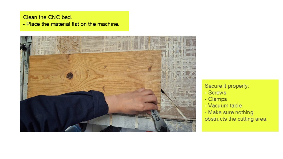
Step 1: Measure and Mark the Wood
Before starting the milling process, I first checked the size of the material using a measuring tape to make sure it matched the available working area of the machine. This step helped me confirm that the design would fit properly without exceeding the cutting limits. Once that was clear, I marked the origin point—usually the lower-left corner—using a pencil, so I could easily reference the starting position during the job.
After that, I secured the material onto the cutting bed, carefully aligning it with the X and Y axes of the machine. I used clamps or screws to hold it firmly in place, making sure none of the fixing elements were in the path of the milling bit to avoid collisions. For thinner materials, I sometimes added double-sided tape or placed a sacrificial board underneath to ensure stability and prevent any movement during cutting.
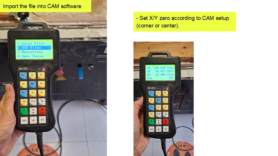
Step 2: Load the Cutting File
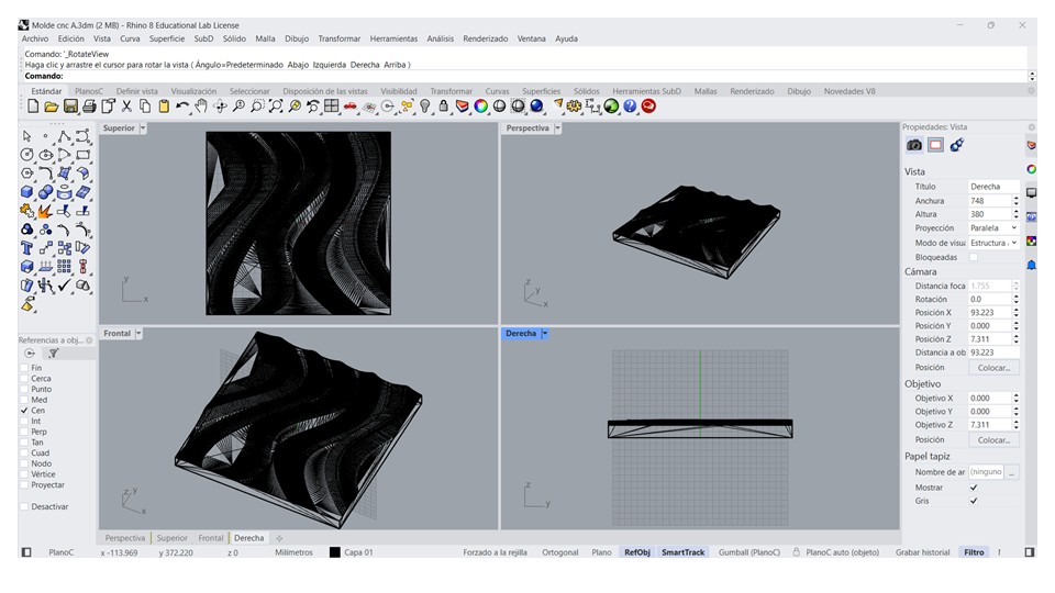
Wavy Wall Modeling in Fusion 360
I began the modeling process by creating a rectangular sketch on the XY Plane, which served as the base geometry for the wall panel. I then extruded the sketch to create a solid body with the desired thickness, establishing the foundation for the rest of the model.
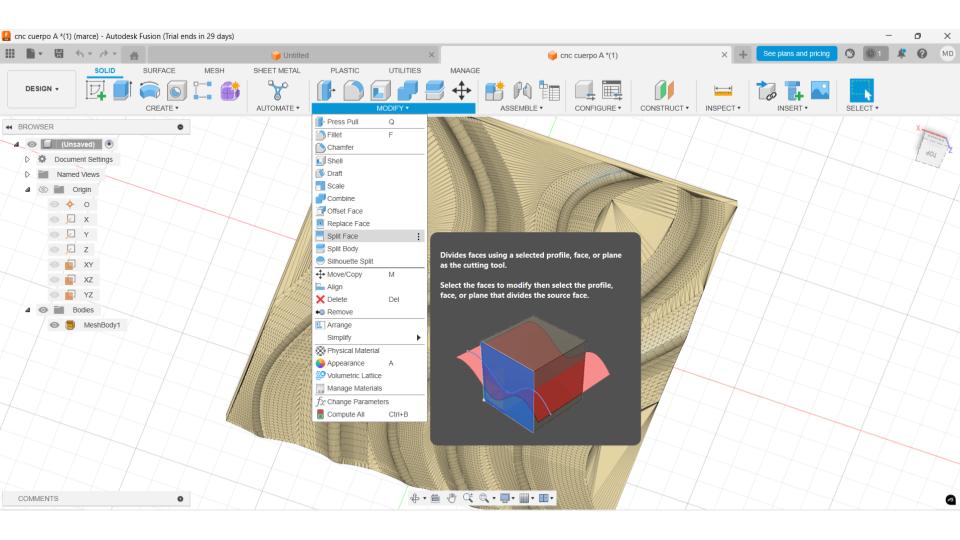
Next, I created a new sketch on the front face of the panel and drew a series of evenly spaced vertical guide lines using the Rectangular Pattern tool. These guide lines allowed me to divide the surface with the Split Face command, creating separate regions that would later help define the wave pattern.
To sculpt the geometry, I entered the Create Form workspace and generated a plane with multiple subdivisions. I selected a relatively high number of subdivisions to provide enough control points for producing smooth and continuous deformations.
Using the Edit Form tool, I moved alternating columns of control vertices forward and backward, creating the characteristic wavy surface. I refined the shape by adjusting individual vertices and applying smoothing operations until I achieved a continuous and organic transition across the panel.
Once I was satisfied with the overall form, I finished the Form operation, allowing Fusion 360 to convert the T-Spline into a BRep solid. When necessary, I applied the Thicken command to add material thickness and finished the model by adding small fillets to soften the edges and improve the final appearance.
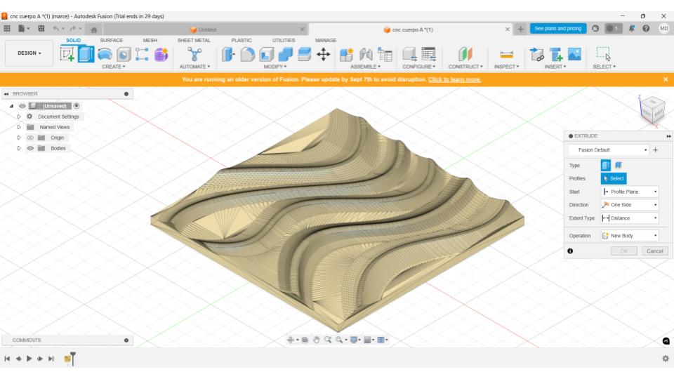
This workflow enabled me to create a smooth, continuous wavy wall panel that is suitable for visualization, prototyping, and CNC manufacturing while maintaining an editable and organized modeling process.
I opened the CNC control software and imported the G-code file, usually in .nc or .tap format, to prepare the job. Before running anything, I always checked the dimensions and simulated the cutting path to make sure the tool movements matched the intended design. This step helped me catch potential errors early and ensured the machining process would run accurately and safely.
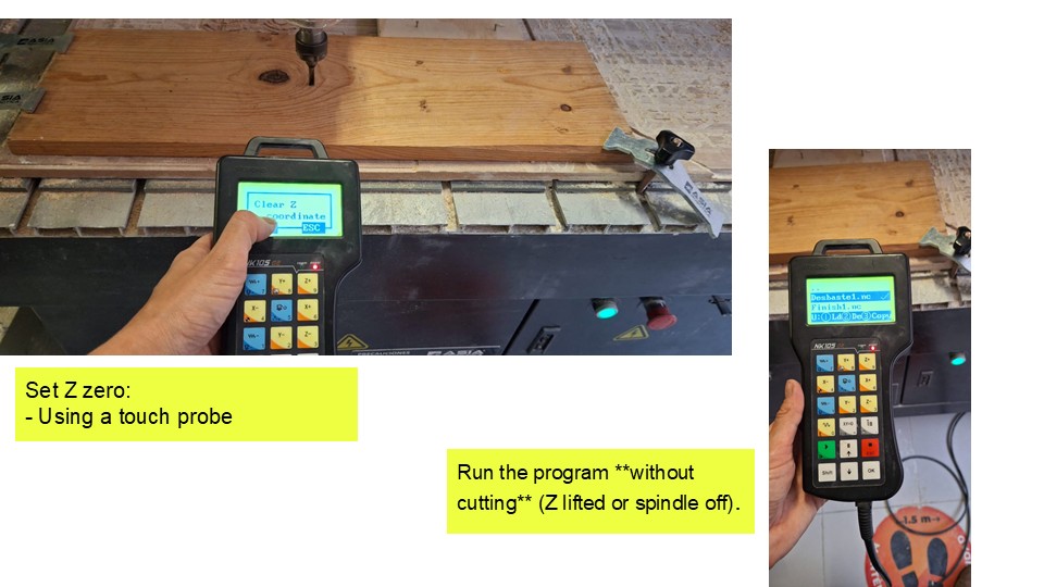
Step 3: Insert the Bit and Set Z Axis
I selected the appropriate milling bit for the job, typically a straight-cut flat end mill (1/8" or 1/4"), depending on the level of detail and material requirements. Then I secured it firmly into the spindle to avoid any movement during operation. After that, I carefully lowered the Z-axis until the bit just touched the surface of the material, taking care not to apply pressure. Once the contact point was set, I zeroed the Z-axis in the software, defining that position as Z = 0.000 to ensure accurate cutting depth throughout the process.
Step 4: Set X and Y Axes
I manually moved the spindle to the origin point that I had previously marked on the material, carefully aligning it with the reference corner. Once everything was positioned correctly, I set that point as the reference in the software by zeroing the X and Y axes. This ensured that the machine would start the job exactly where I intended, maintaining alignment between the digital file and the physical material.
Step 5: Simulate and Double-Check
Before starting the milling process, I reviewed the toolpath carefully to make sure it wouldn't collide with any clamps or screws holding the material in place. I also double-checked that the material was firmly secured on the bed, since any movement could affect the accuracy of the cut. Finally, I verified the bit height and confirmed the maximum depth of cut to ensure the machine would operate safely within the material limits.
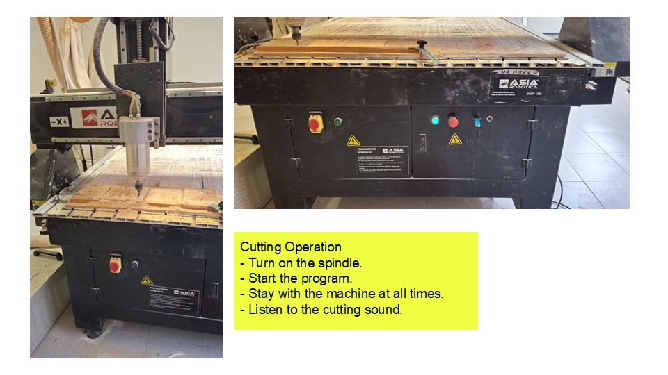
Step 6: Start the Cut
Once everything was set, I started the job from the CNC software and carefully watched the first few seconds to make sure the machine was moving correctly and behaving as expected. I stayed close to the machine throughout the process, since it's important not to leave it unattended while it's running. If I noticed anything unusual—like unexpected noise, vibration, or movement—I was ready to stop the machine immediately using the emergency stop button to prevent damage or errors.
Step 7: Cleanup and Shutdown
Once the machining process finished, I waited until the bit came to a complete stop before approaching the machine. Then I carefully removed the cut material, making sure not to damage any edges or remaining fixtures. After that, I cleaned the work surface using a vacuum or compressed air to remove all dust and debris. Finally, I stored the milling bits properly and shut down the machine to leave everything clean and ready for the next use.
Additional Tips
- Always wear hearing and eye protection.
- Never leave tools on the cutting bed.
- If unsure about your file or parameters, ask a technician or run a test on cardboard or foam.
- Document your settings for future use.
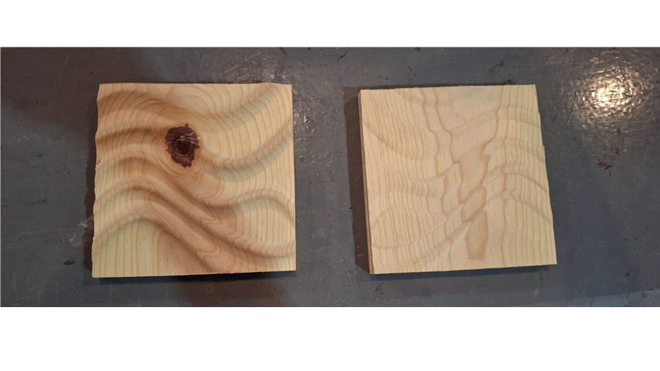
Leather Forming Using the CNC Mold
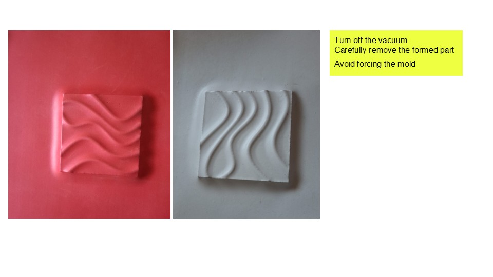
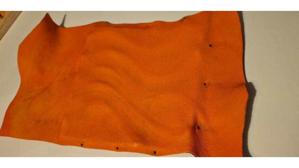
Using the mold previously machined on the CNC, I decided to experiment with shaping a piece of orange leather. To make the material more flexible and easier to form, I soaked it in a mixture of warm water and white glue. Once the leather had softened, I stretched it over one half of the mold so that it would retain the desired shape as it dried. To maintain tension across the surface, I secured the leather with nails around the perimeter. I then placed the opposite half of the mold on top, creating a press that held the material firmly in place overnight.
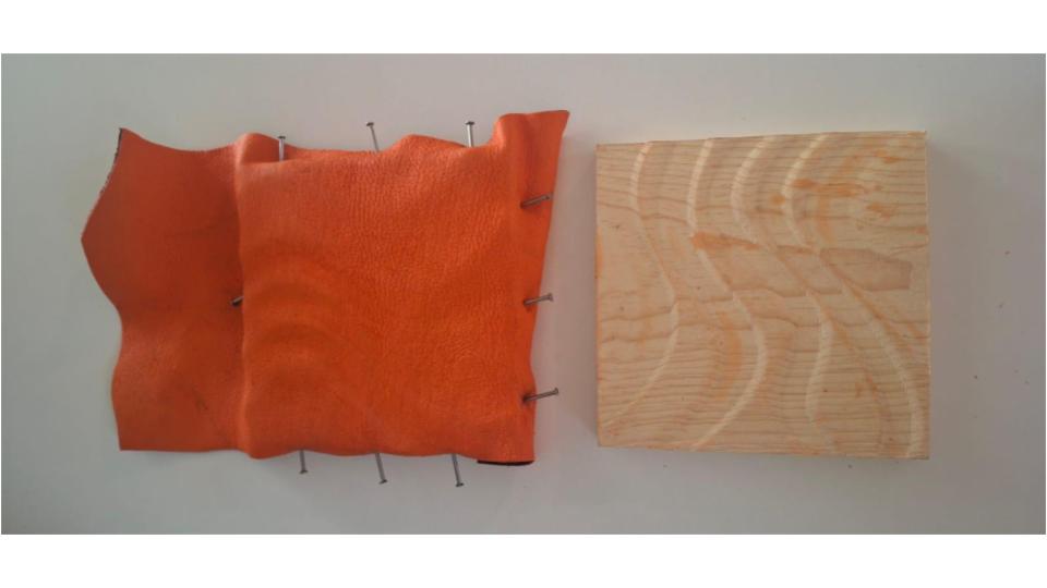
The following morning, I continued conditioning the leather by applying small amounts of the warm water and white glue mixture with my finger, ensuring that the material remained pliable while adapting to the mold's geometry. After approximately 48 hours, once the leather was completely dry, I removed it from the mold. The resulting piece successfully retained the undulating surface of the mold, demonstrating how wet-forming techniques can be used to transfer complex three-dimensional geometries into leather.
Documenting and Comparing Experiments
Comparison: CNC-Milled Mold vs. Borax Crystal Mold
| Characteristic | CNC-Milled Mold (Wood) | Borax Crystal Mold |
|---|---|---|
| Base Material | Wood (pine, MDF, or similar) | Flexible structure (faux leather, wire, string) |
| Creation Method | Computer-assisted cutting with CNC router | Chemical growth of crystals on a surface |
| Main Function | Rigid, reusable mold for shaping materials | Decorative or textural sculptural element |
| Durability | High (structural and long-lasting) | Fragile (crystals can break easily) |
| Detail Level | High (depends on digital design and tool size) | Low to medium (based on organic crystal growth) |
| Reusability | High (if well maintained) | Low (crystals are delicate and moisture-sensitive) |
| Production Time | Medium (depends on design and cutting) | Slow (crystals need several hours or days to grow) |
| Production Cost | Medium to high (material and machine-dependent) | Low (cheap materials: borax, water, string, etc.) |
| Ideal Application | Prototypes, functional molds, small-scale production | Artistic work, material exploration, textures |
| Aesthetic | Precise, clean, industrial | Organic, natural, crystalline |
| Sustainability | Depends on wood source | Borax is biodegradable, but not entirely harmless |