5. E-textiles
References
Anuvad is an Ahmedabad, India, based studio doing project like these that combine traditon and tech.
Project Jacquard to weave interactivity into textiles
Both these projects incorporate tech, especially electronics, into fabric, to make material and objects that are sensitive, reactive, and interactive.
Research
How to Get What You Want, also known as Kobakant.at, is the premier resource for all things fabric x electronics x DIY. I am thoroughly amazed at the ingenuity of the builds documented here.
Here are some of my frequent references.
General e-textile sensor references
- Handcrafting Textile Sensors from Scratch - Hannah Perner-Wilson / Kobakant
- Kobakant - Soft Technology Handbook
Pressure and squeeze sensors
- Kobakant - Paper + Aluminum Foil Pressure Sensor
- Kobakant - Felted Pompom Pressure Sensor
- Kobakant - Neoprene Pressure Sensor
- Kobakant - Neoprene Bend Sensor
- Kobakant - Pressure Matrix code + circuit
Textile sliders and potentiometers
- Kobakant - Fabric Potentiometer
- Kobakant - Tilt Potentiometer
- Kobakant - Tilt Potentiometer 2
- E-Textile Swatch Exchange - Beaded Tilt Sensor
Analog readings and voltage divider
- Kobakant - Voltage Divider with Arduino
- Adafruit - Force Sensitive Resistor: Using an FSR
- SparkFun - Force Sensitive Resistor Hookup Guide
NeoPixels and wearable output
I had worked with NeoPixels extensively during my FabAcademy final project, and I had found these links very very handy.
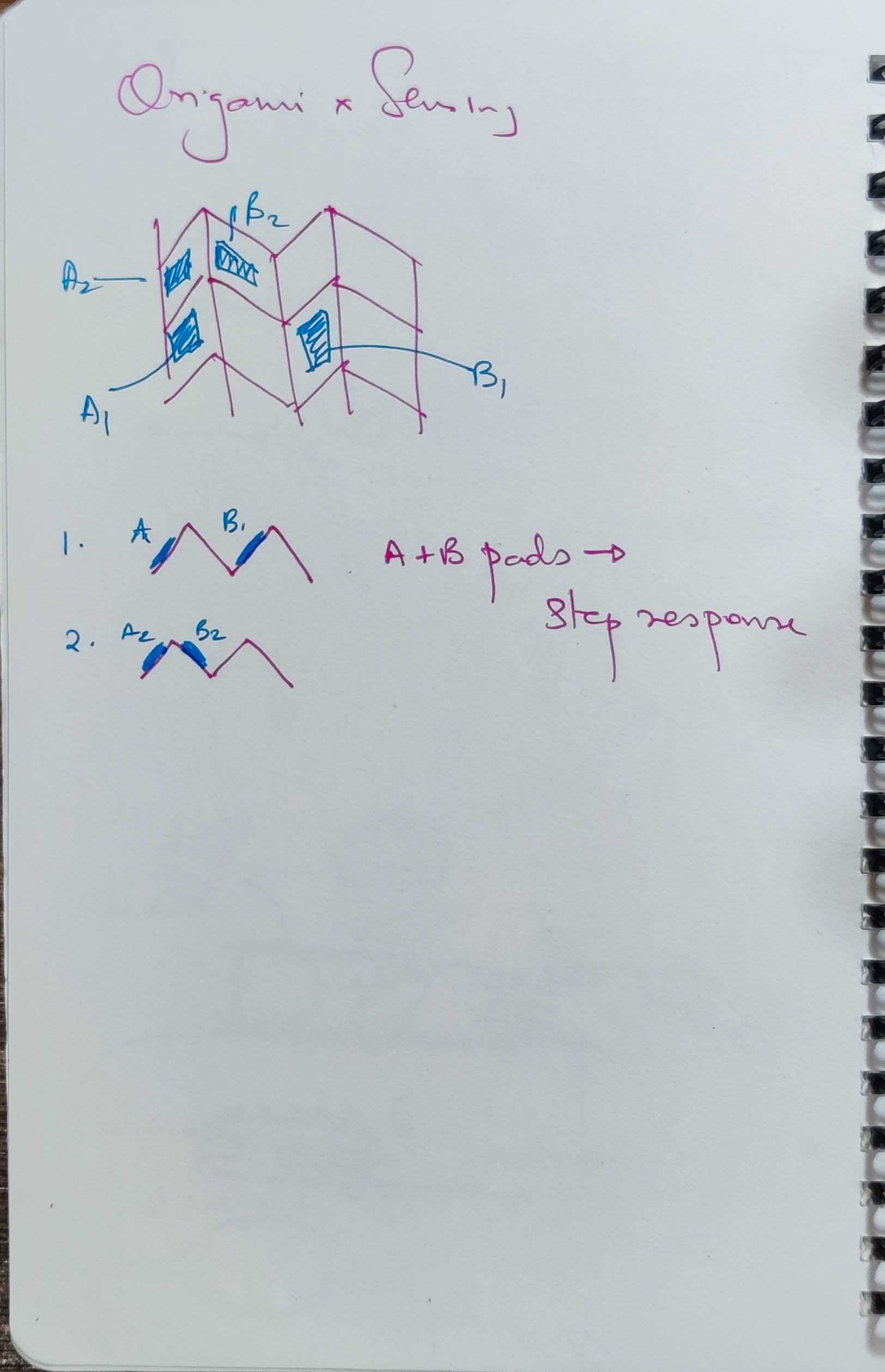
Ideation
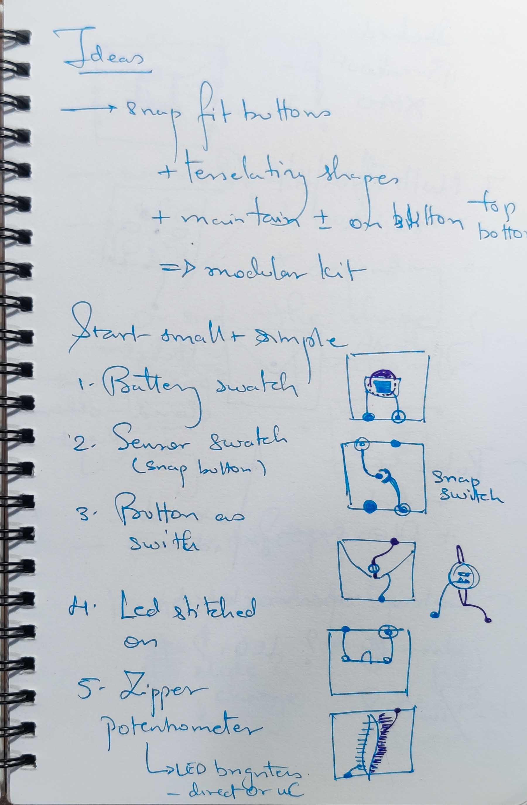
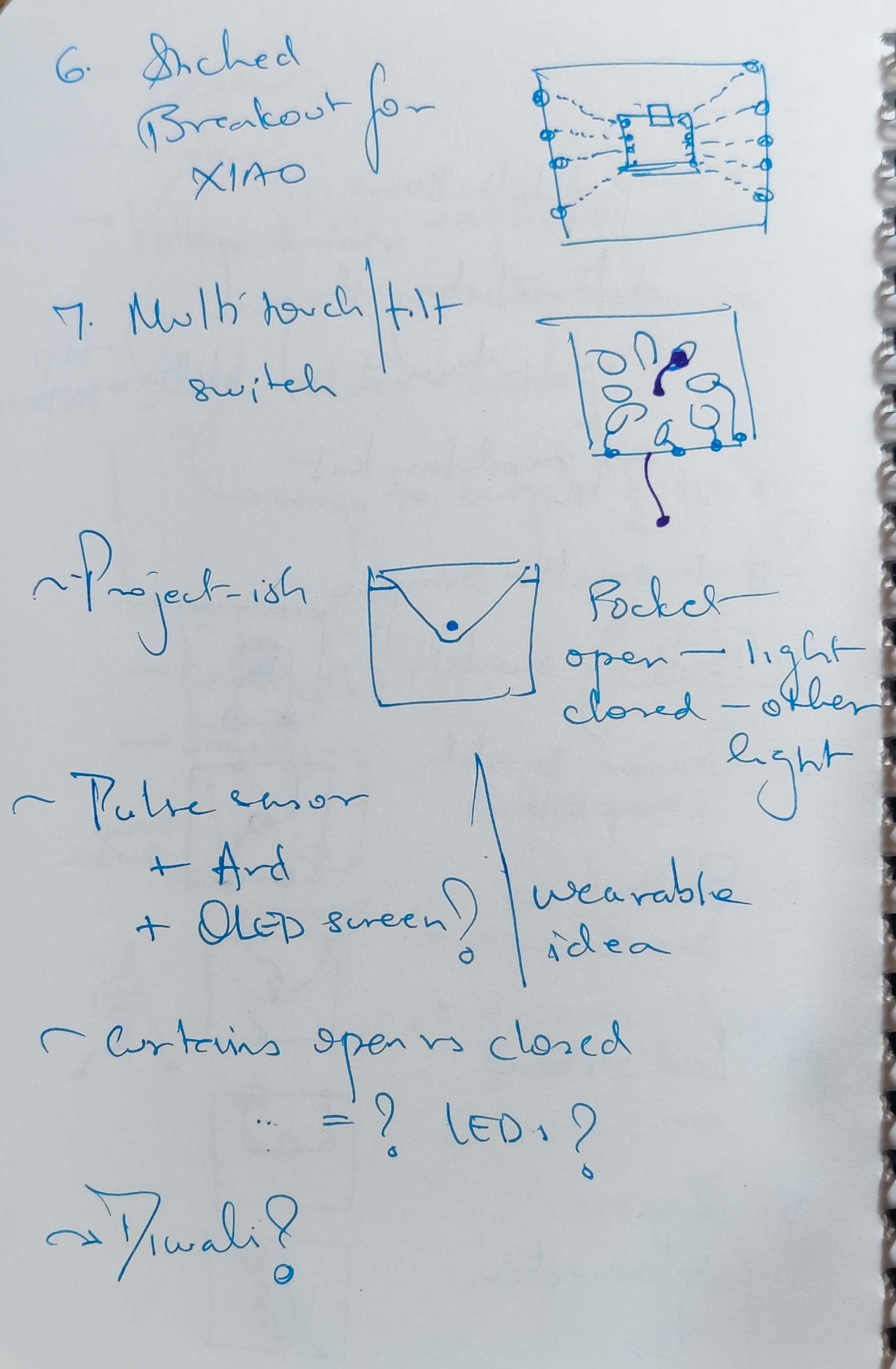
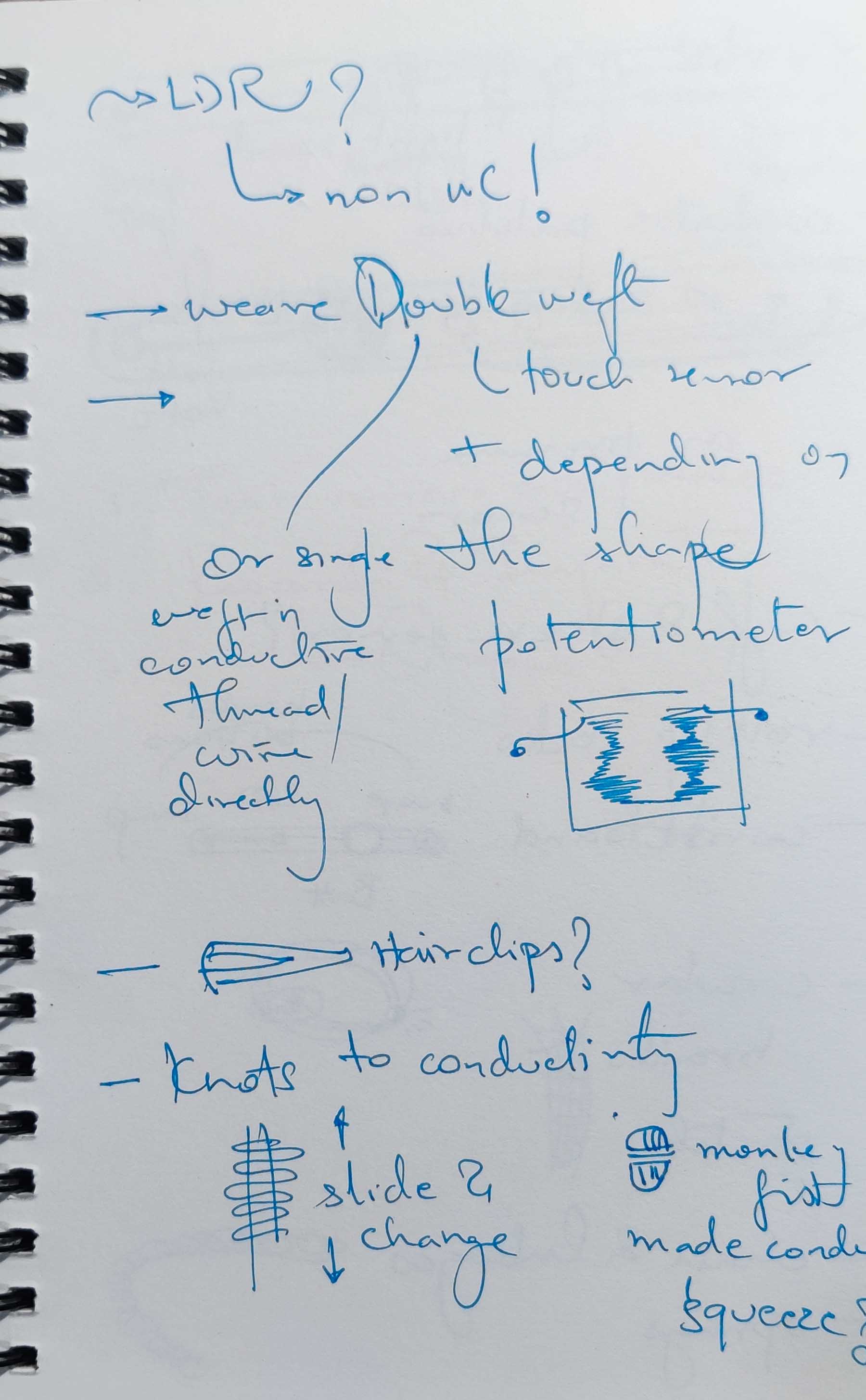
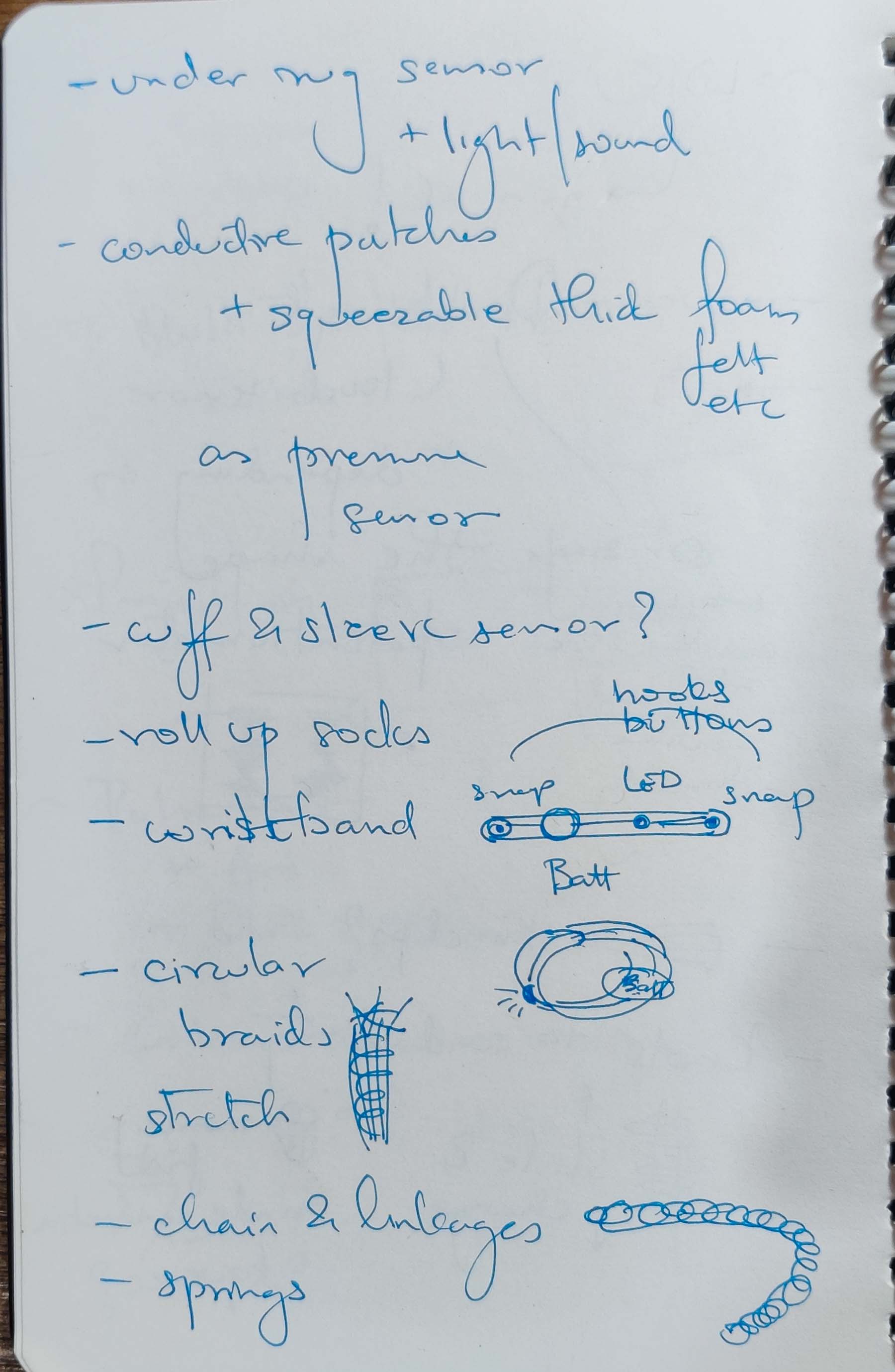
I had several ideas to use everyday items to turn into sensors by hijacking their conductive and insulating properties.
List of items :
- snap buttons
- metal beads
- wires and conductive thread
- metal wool from kitchen vessel scrubber
- velostat fabric
- copper or aluminium foil pieces/tape
These could be used to make digital On/Off switches or analog sensors with a range of outputs.
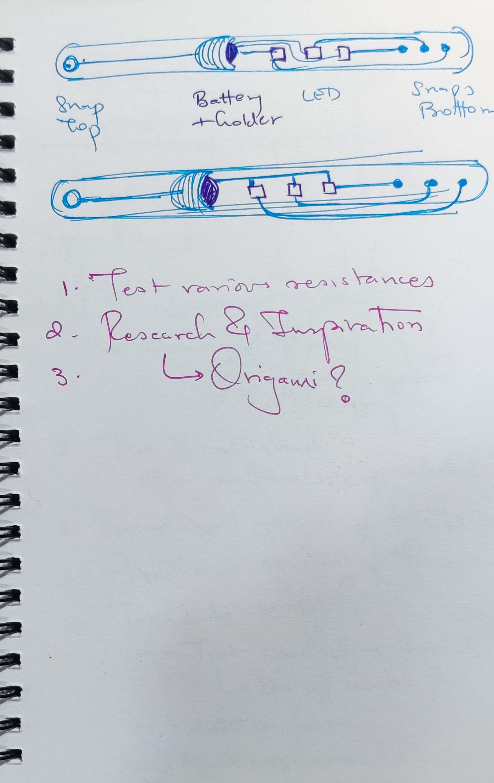
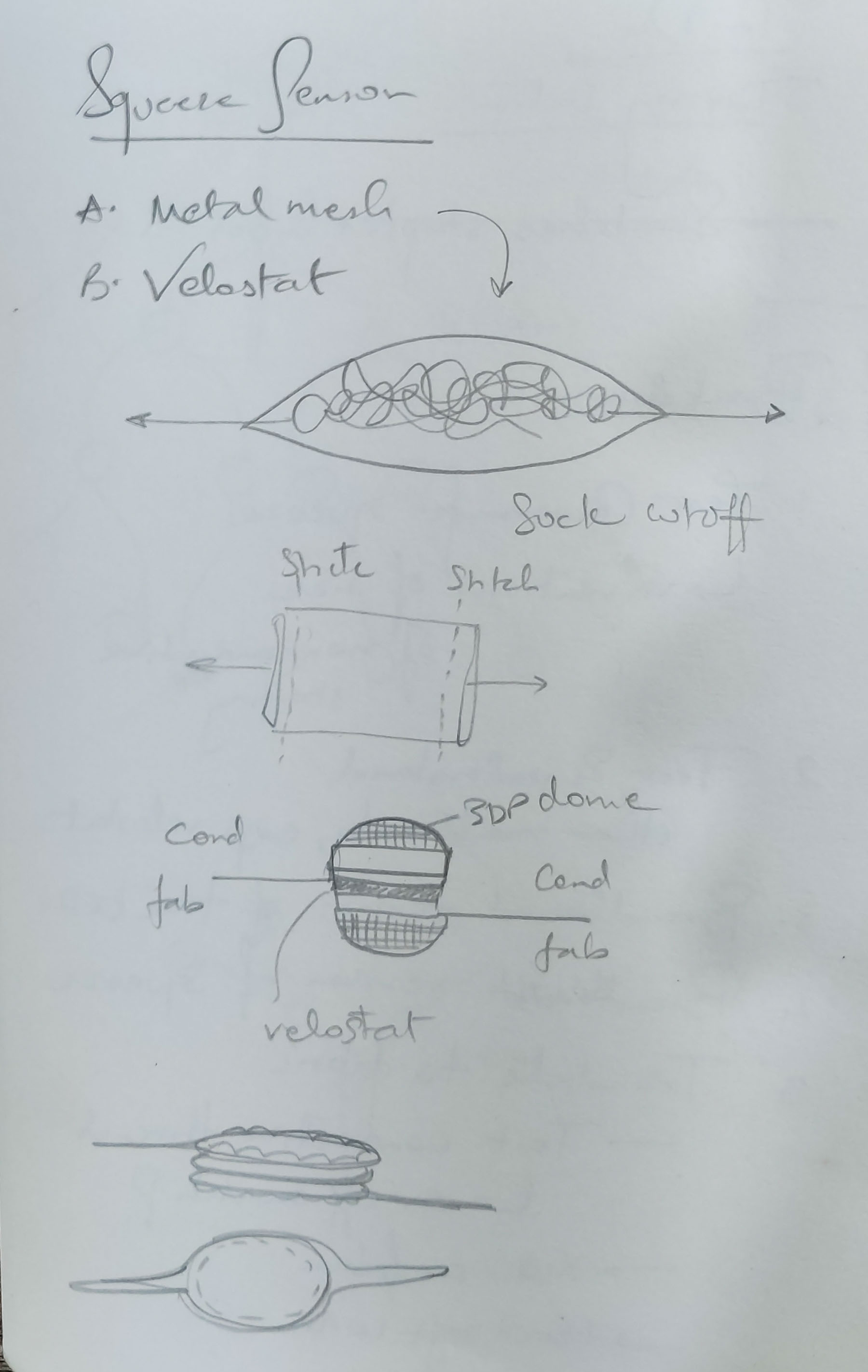
Fabric sensors
Digital switch
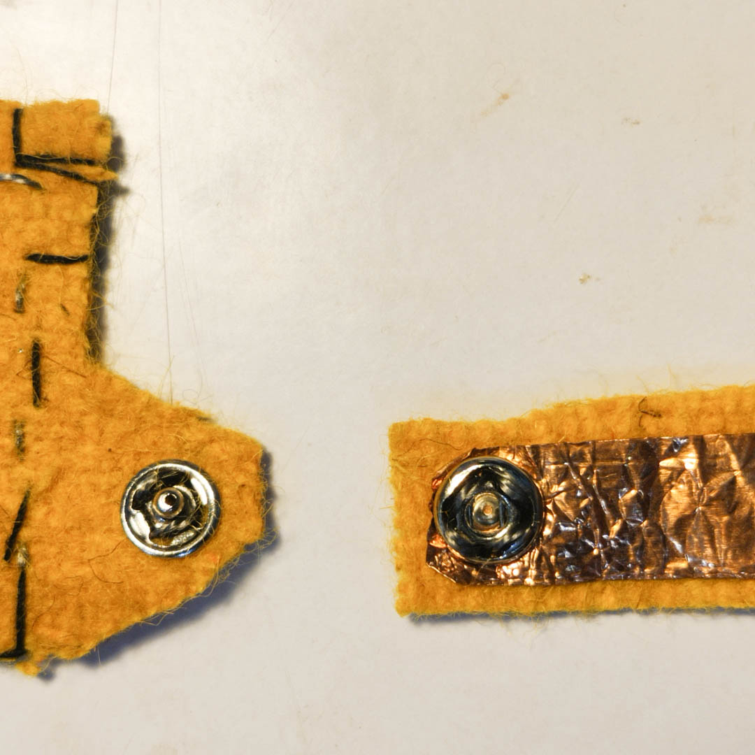
A snapfit/ press button attached using either fine copper wire or with conductive thread acts as an On-Off digital switch.
Pressure sensor 1 - Squeezee
A steel mesh pot-scrubber, when squeezed, increases contact between it's strands, and drops in resistance. This change in resistance can be used to infer pressure.
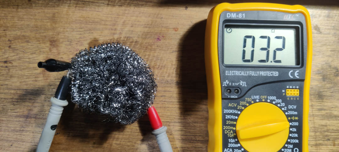
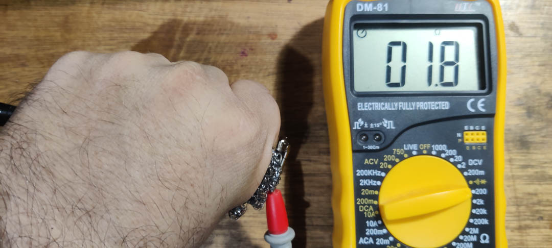
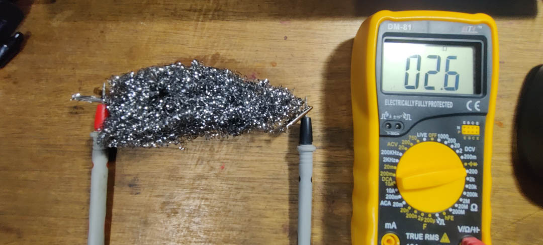
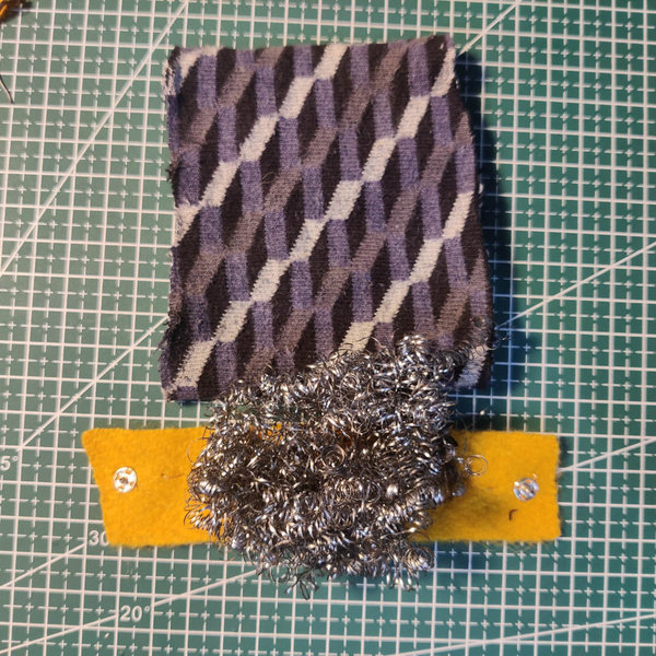
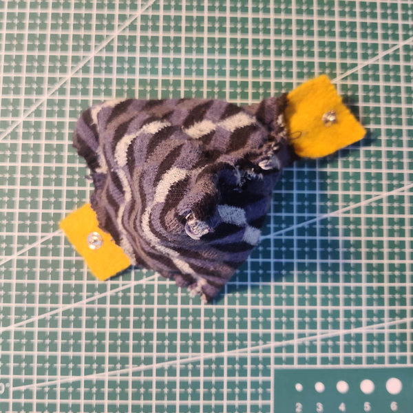
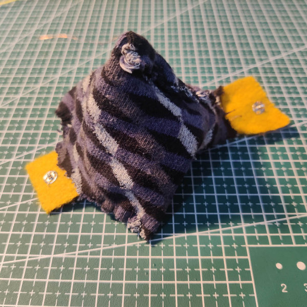
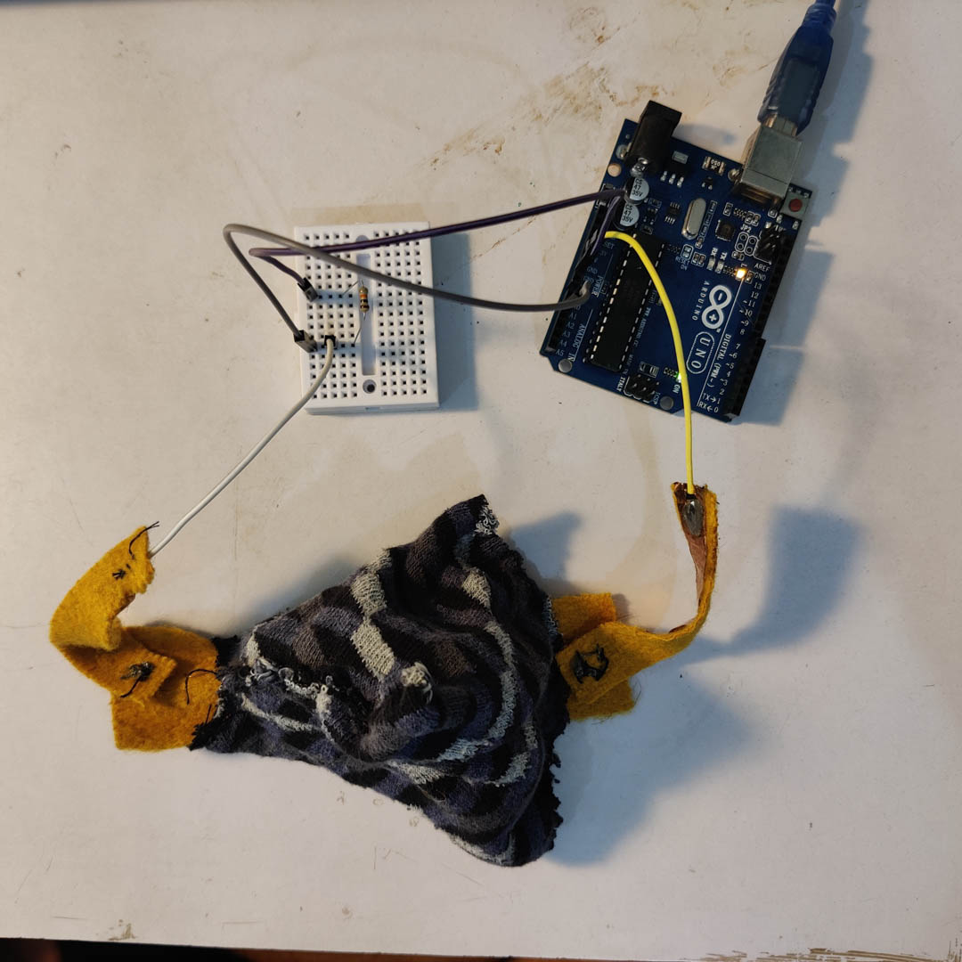
While it does show a change in resistance when squeezed manually, enclosing it in the fabric samosa pocket seems to bring the mesh closer/make it denser, so the range of the variation is reduced quite a lot. This will have to be debugged later - either by opening it up and removing material, and/or adding insulating fibres like paper or cotton or fabric shreds into the mix.
Pressure Sensor 2 - Velostat
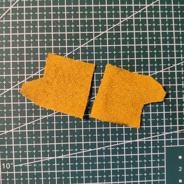
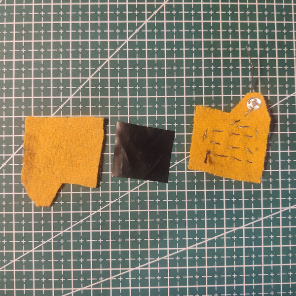
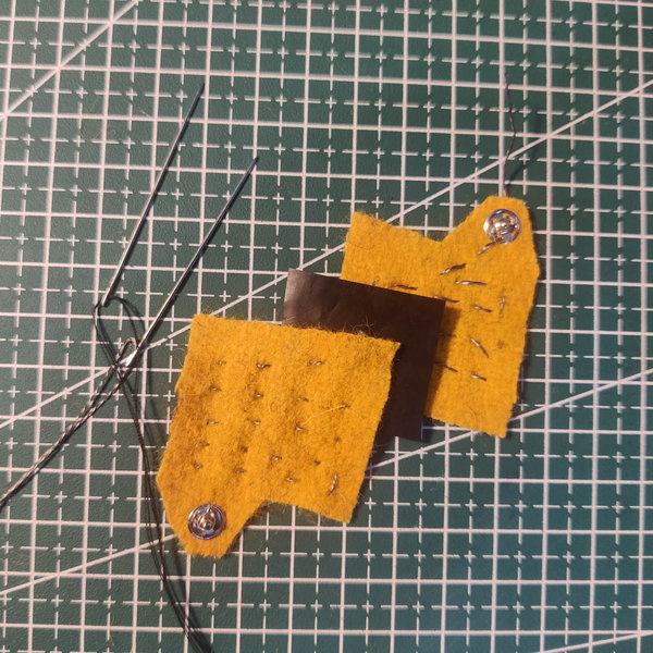
Next I used a velostat piece sandwiched between 2 felt pieces from the OSCF week.
I stitched up a series of running stitch lines using conductive thread on both felt pieces to create contact between the velostat and the snap buttons, to which other conductive paths could be attached to complete the circuit.
Next I stitched together the entire sandwich of felt-velo-felt with regular thread and a blanket stitch to seal up the edges.
I made two arms using felt strips, with the other half of the snap fit buttons stitched at one end, Cu tape from button to other end, and jumper wires soldered to the Cu tape end.
The final circuit would be
Arduino pin - jumper - Cu tape - snapbutton - velostat sandwich - snapbutton - Cu tape - jumper - Arduino pin
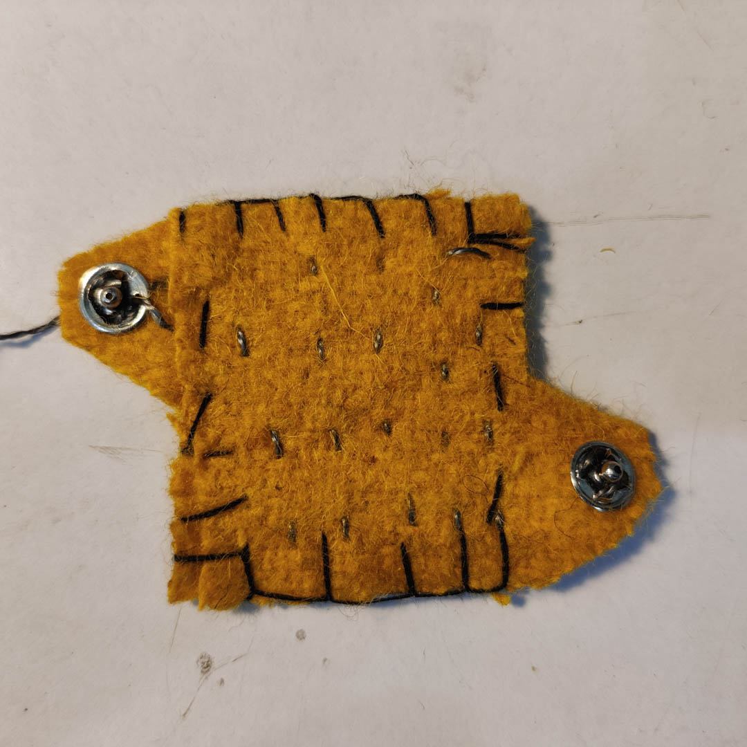
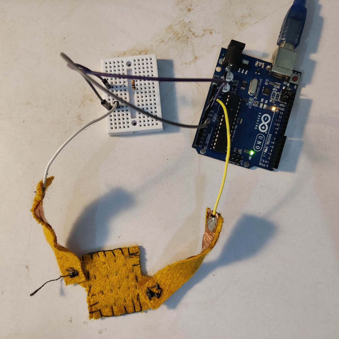
Effectively, this was
- a pressure sensor, with the velo-sandwich as the sensor
- an on-off switch or digital sensor, if the snap buttons were engaged/disengaged
Serial response from Velostat
The Velostat wasnt very responsive to pressure as a gradient, but it would conduct beyond a threshold, so it worked like an on-off switch with very little ramping.
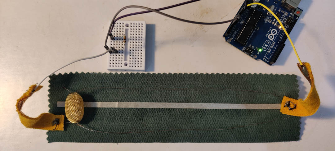
Slider 1 - Bead with conductive fabric
(pressfit buttons version)
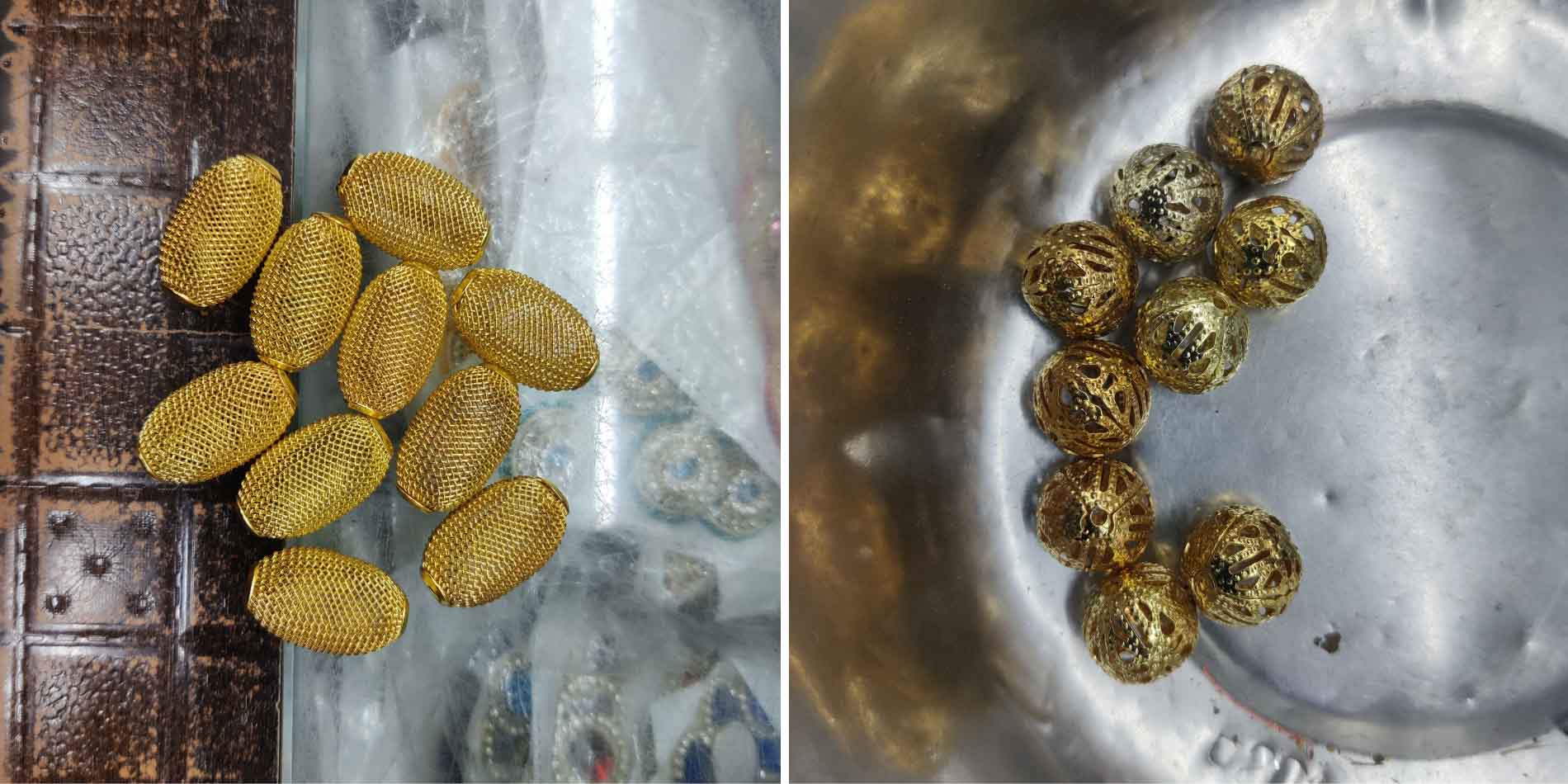

This was a simple slider consisting of :
- a fabric base
- a strip of conductive fabric
- a metal bead
- thin Cu wires
- pressfit buttons
- the jumper + Cu tape + pressfit button felt arms from the pressure sensor
The circuit was was follows :
- the arduino pins connect to each felt arm through the jumper
- the pressfit buttons on one jumper arm connects to it's mating half on the base fabric
- the pressfit button is stitched into the base fabric + conductive fabric strip using Cu wire
- the conductive fabric is in sliding contact with the metal bead
- the metal bead has 2 Cu wires running through it and anchored to the base fabric.
- 2 wires were used to mantain symmetric tension and keep the bead aligned to the conductive fabric
- they also increased the friction in sliding the bead and made the positioning more controlled
- one of the wires is connected to another half of a pressfit button stitched into the base fabric
- the felt arm has the mating half of the pressfit
The circuit is complete when the pressfit arms are connected to the arduino pins and the mating pressfit buttons The sensor effect comes from the sliding bead and the varying length of the conductive fabric in the circuit
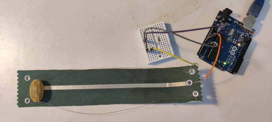
Slider 2 - Bead with conductive fabric
(aglet version)
Same as the pressfit version but faster to execute since I used aglets - pressfit rivets with a hole, typically used to reinforce shoelace holes in shoes. Being metal, they are conductive. Being pressfit rivets, they saved a lot of stiching time.
This was a simple slider consisting of :
- a fabric base
- a strip of conductive fabric
- a metal bead
- thin Cu wires
- aglets
- jumper cables cut in half and stripped The circuit was was follows :
- the arduino pins connect to the jumper
- the bare end of the jumper is connected to a Cu wire which is connected to the aglet
- the aglet is pressfitted into the base fabric + conductive fabric strip using its pressing tool
- the conductive fabric is in sliding contact with the metal bead
- the metal bead has 2 Cu wires running through it and anchored to the base fabric.
- 2 wires were used to mantain symmetric tension and keep the bead aligned to the conductive fabric
- they also increased the friction in sliding the bead and made the positioning more controlled
- the 2 strands of Cu wire are actually one length of wire threaded from one corner of the base fabric to the diagonally opposite corner through the bead, and then under the short side of the base fabric, up through the neighbouring aglet, and again diagonally across to the remaining corner via the bead.
- the felt arm has the mating half of the pressfit
The circuit is complete when the pressfit arms are connected to the arduino pins and the mating pressfit buttons The sensor effect comes from the sliding bead and the varying length of the conductive fabric in the circuit
Basic Analog Sensor code
Can be used for any analog sensor. The sensor creates a voltage drop between the 5V and the A0 input pin, and the 10k resistor prevents noise on the A0 pin by grounding it when not receiving an input.
// Analog Sensor Read

int sensorPin = A1;
int sensorValue = 0;

void setup() {
  Serial.begin(9600);
    pinMode(sensorPin, INPUT);

}

void loop() {
  sensorValue = analogRead(sensorPin);
  // Serial.print("Sensor value: ");
  Serial.println(sensorValue);
  delay(500);
}
Analog Sensor Connections
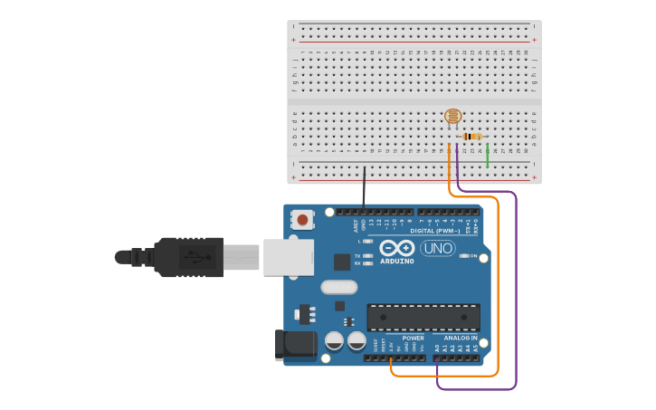
Sensor terminals - 5V and A0
10k resistor - A0 and Gnd
Replace the LDR in the circuit with the crafted sensor.
Serial output

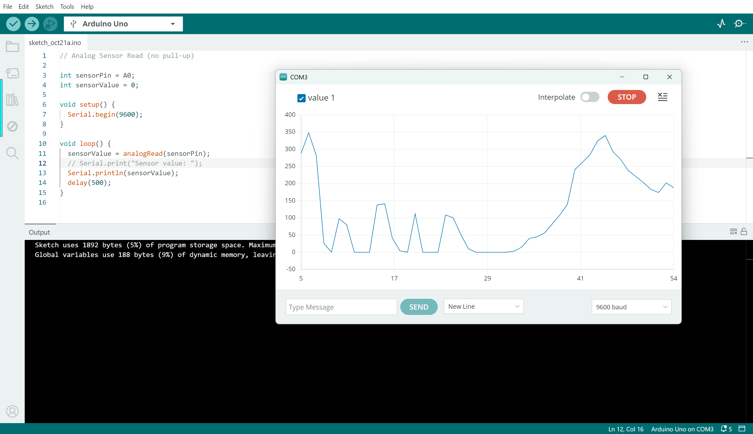
This is fairly random, I am still trying to debug what is wrong here.
The range of ressitance offered by the length of conductive fabric vs the conductivity of the cu wire is resulting in a very low band of variation across the length of the conductive strip, and this makes it prone to being affected by other factors. While it is working in principle, I would want to work on this further before any practical applications can be made.
After trying the sliders as analog sensor inputs with a 10kOhm pulldown ressistor connected to ground as described above and not getting good results, I also tried them as a voltage divider circuit with a 1 Ohm ressistor (since both conductive fabric strips were registering at about 2.9-3.5 ohms on the full length, so about 1.5 ohms at half length, and the 1 ohm resistor was a close equivalent for the fixed resistor in the voltage divider)
However, results continued to be erratic, and so I stopped.
My next attempt would have been to put the strip into a Wheatstone bridge, if I wanted to try to make it work.
But I also suspect the metal bead made of wire mesh has a bad connection with the collar of the bead where the wires are threaded through, so the bead may be part of the problem here as well.
Hard soft connections
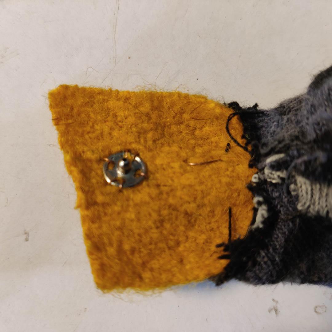
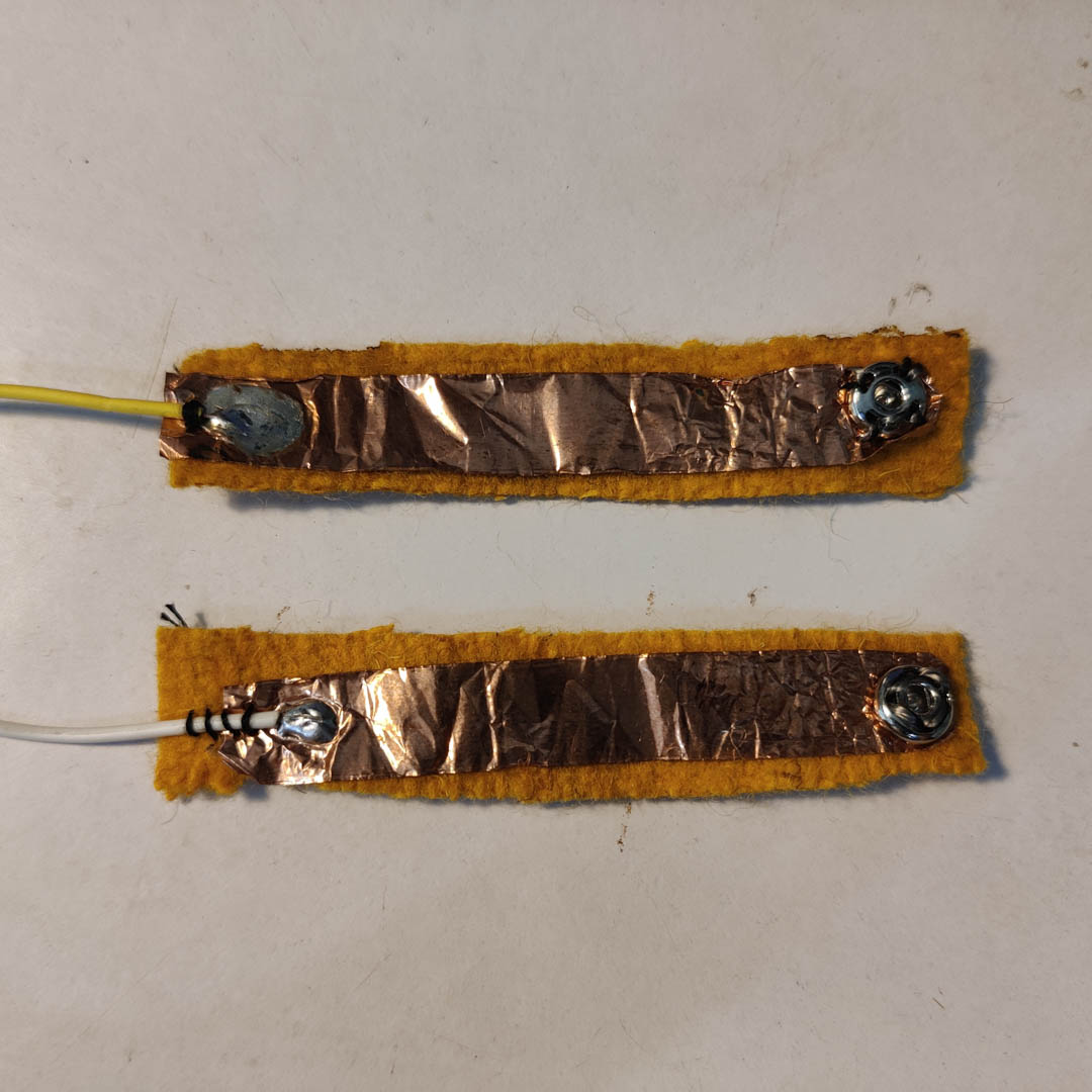
These were some of the hard-soft connections I explored for this exercise
-
Pressfit buttons + Conductive thread
-
Pressfit buttons + Fine Copper wire
-
Copper tape + Pressfit buttons + Conductive thread
-
Copper tape + Jumper wires
-
Copper wire + Conductive Thread
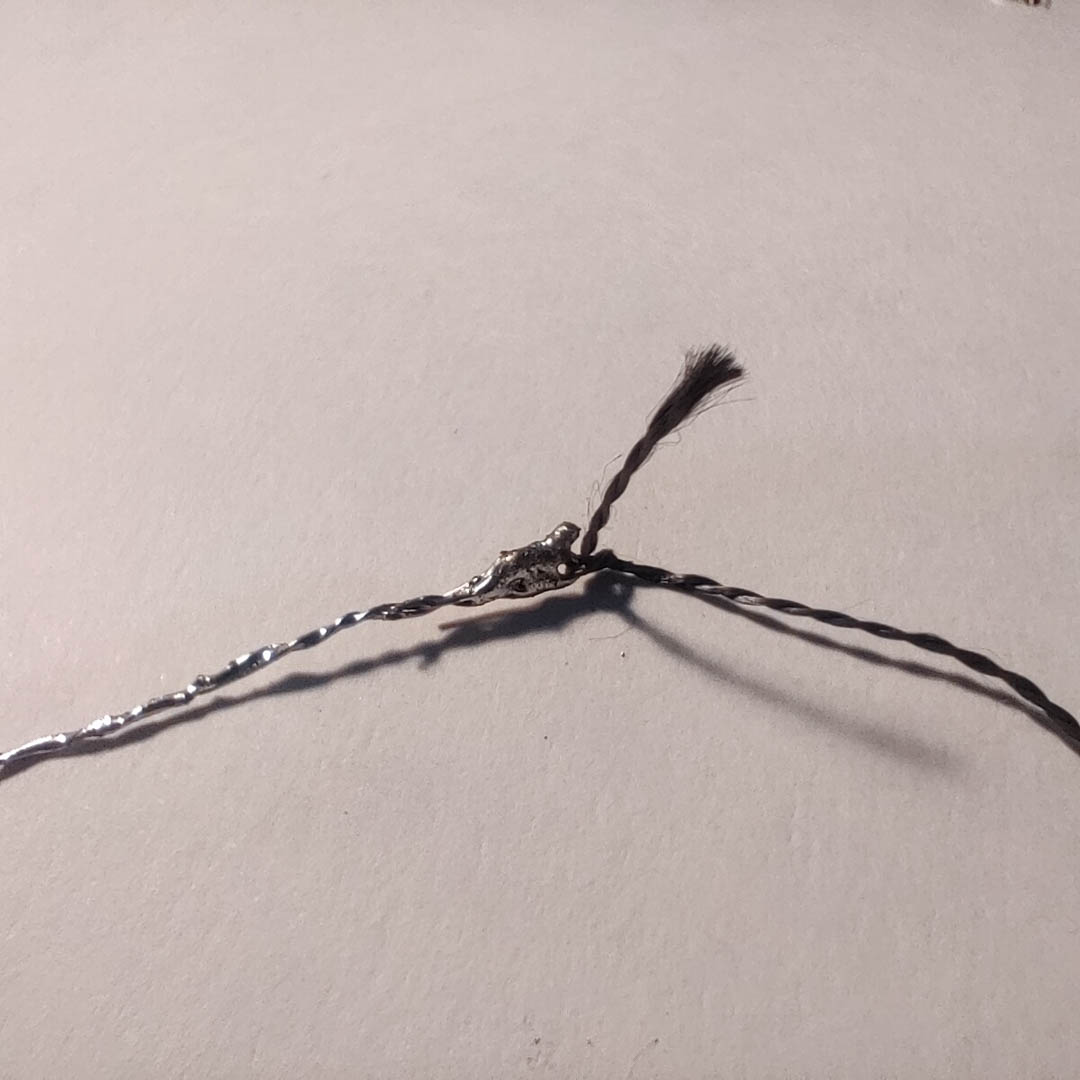
-
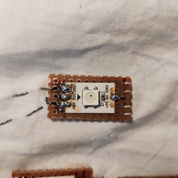
Conductive thread + Perf-board
Project - Wearable Vambrace with glowing motifs
Concept
A wearable vambrace - a forearm armour used in the middle ages by archers as well as falconers training their falcons and hawks - with pressure sensor based NeoPixel lightup.
I wanted to use the squeeze or pressure sensor as an input, and based on the level of the input, light up neoixels.
The mapping would be :
Pressure -> Brightness
OR
Pressure -> Number of LEDs
Though I had stared with just lighting up some neopixel LEDs, eventually I settled on creating the White Tree of Gondor, defined by Neopixel LEDs.
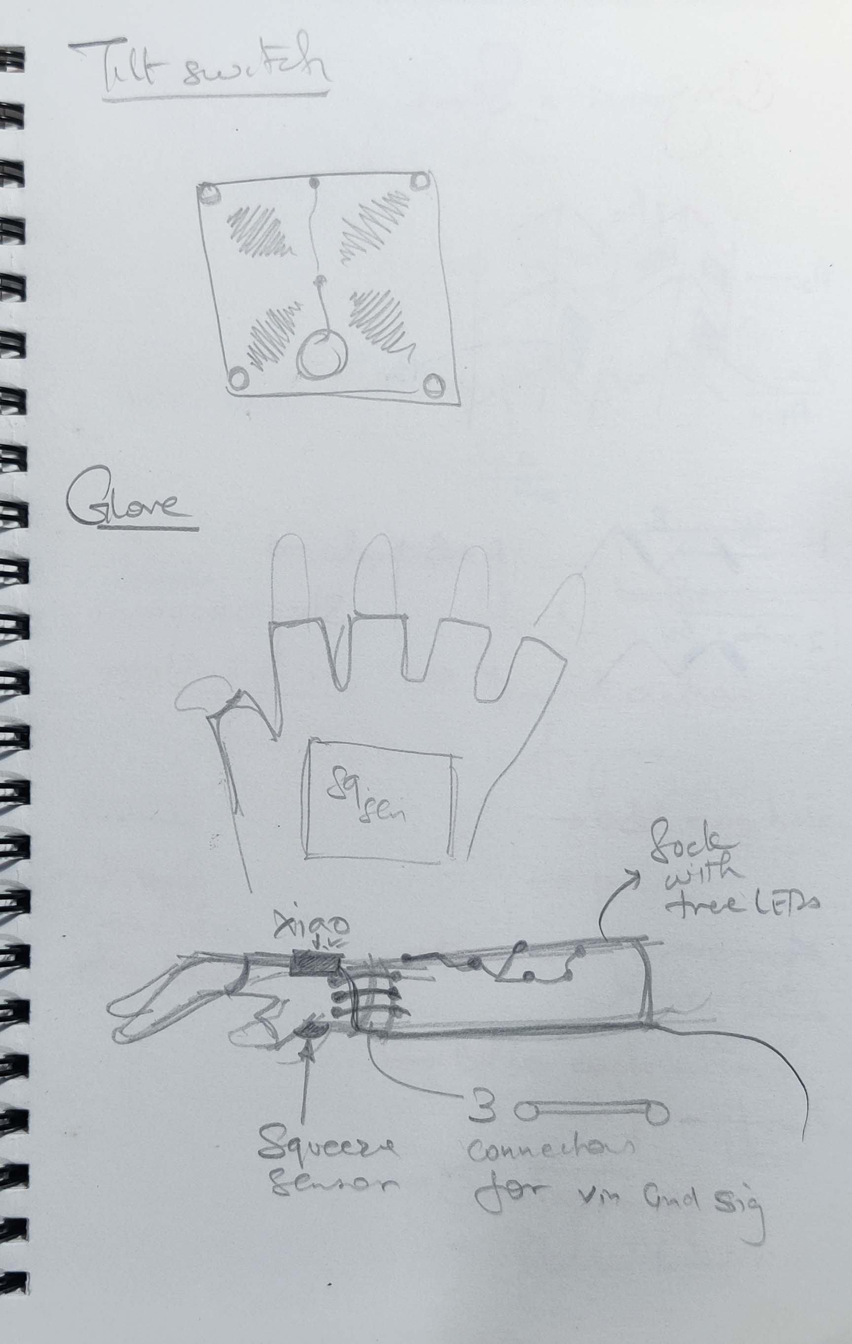
The tree motif would be on a forearm covering vambrace, while the sensor would be in the palm of the glove, to be activated by squeezing. The microcontroller, currently an Arduino Uno, would be the Xiao RP2040, stitched onto the back of the hand.
The vambrace would have aglets to easily lace it up onto the forarm.
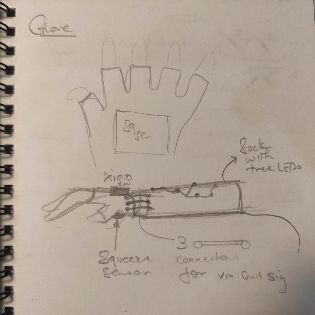

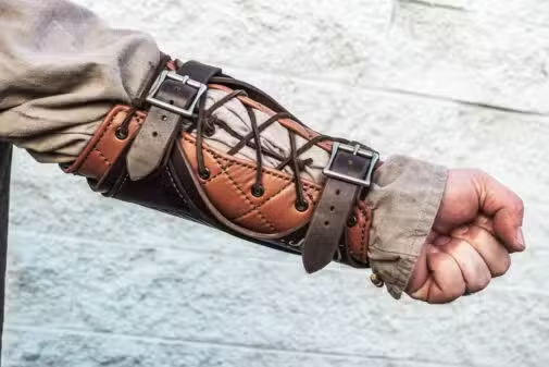

I found the image at the very end of the week, of the same concept but in leatherwork !
Image credits : Grommet's leathercraft, Black Raven Armoury
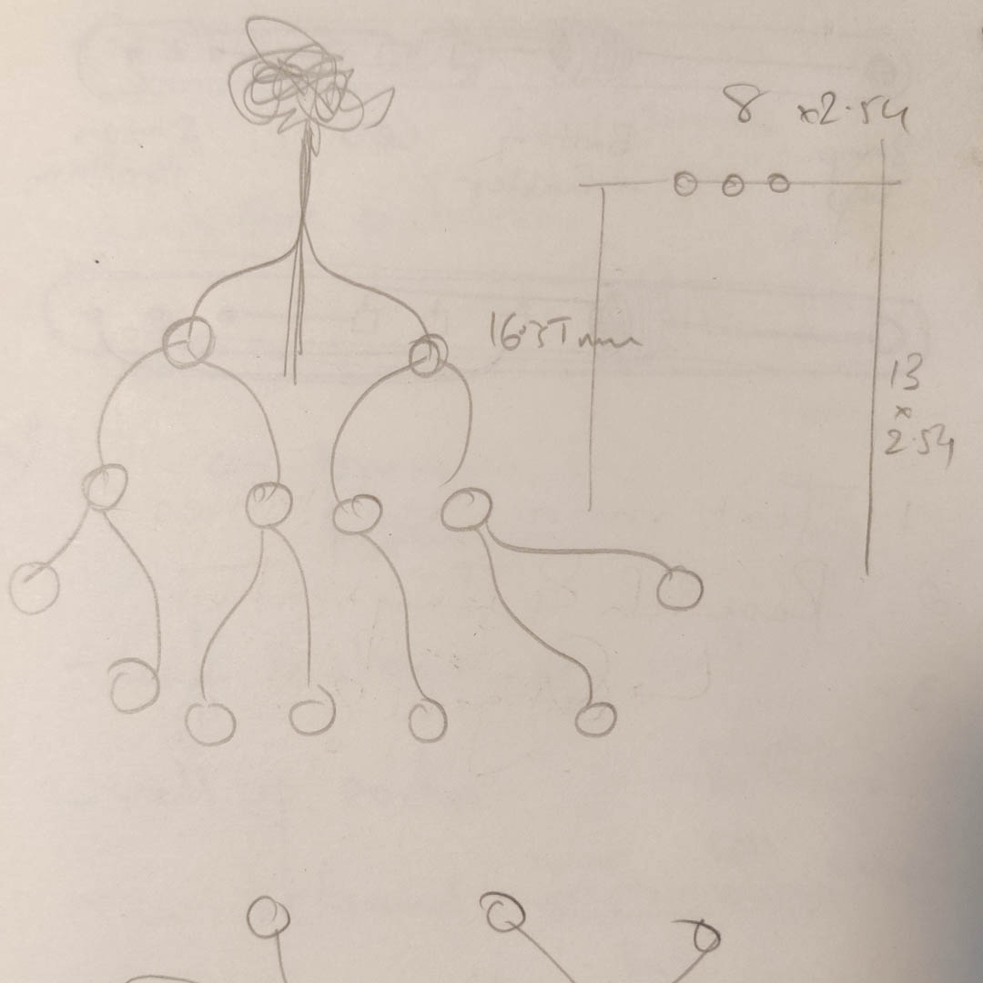
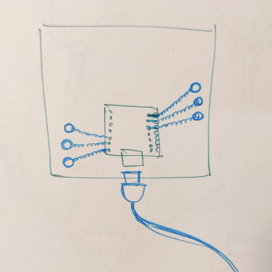
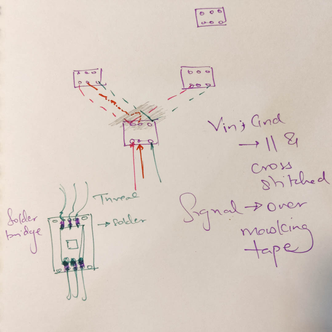
Neopixel Tree sketch
XIAO on fabric
neopixels on perfboard 0 attachment plan
Process
I started with cutting perfboards ot size and filing them clean. One board for each neopixel, with an extra row of holes at both sides to be able to stitch the perfbaord pieces into the fabric.
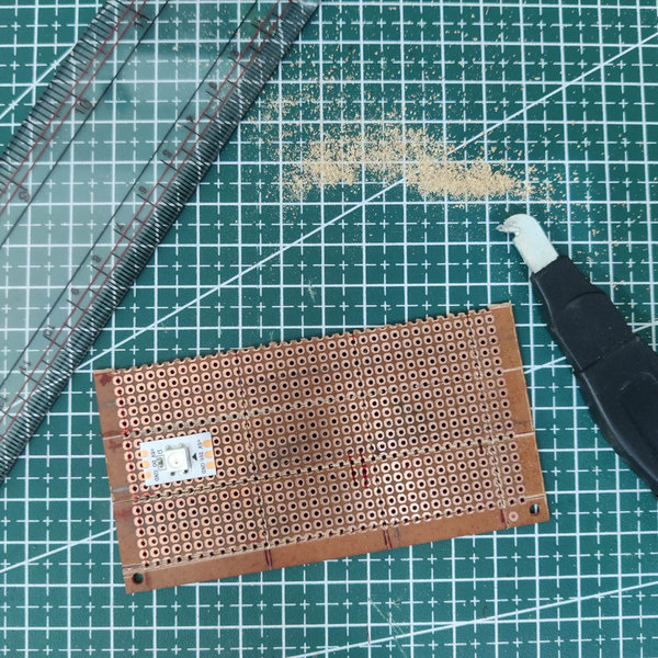
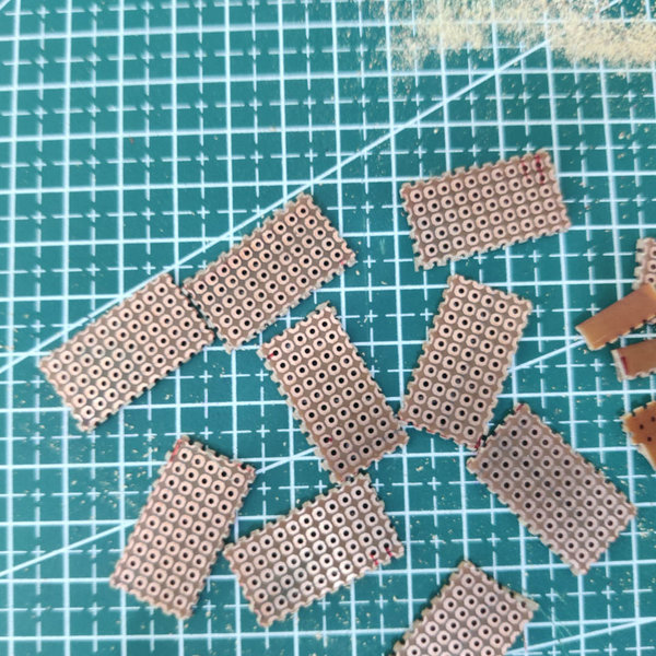
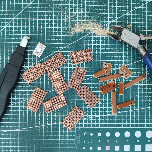
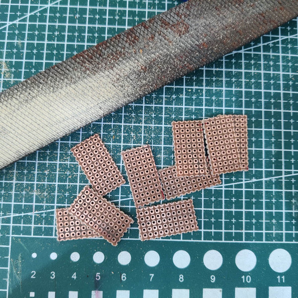
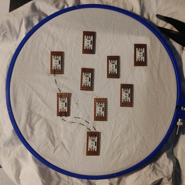
Once the perfboards were cleaned, I cut up a neopixel adhesive strip and glued each led in place on the boards. Then they were placed on their location and a few small stiches of thread kept them in place. Once they were staying put, I traced the +5V and GND paths across the fabric from LED to LED.
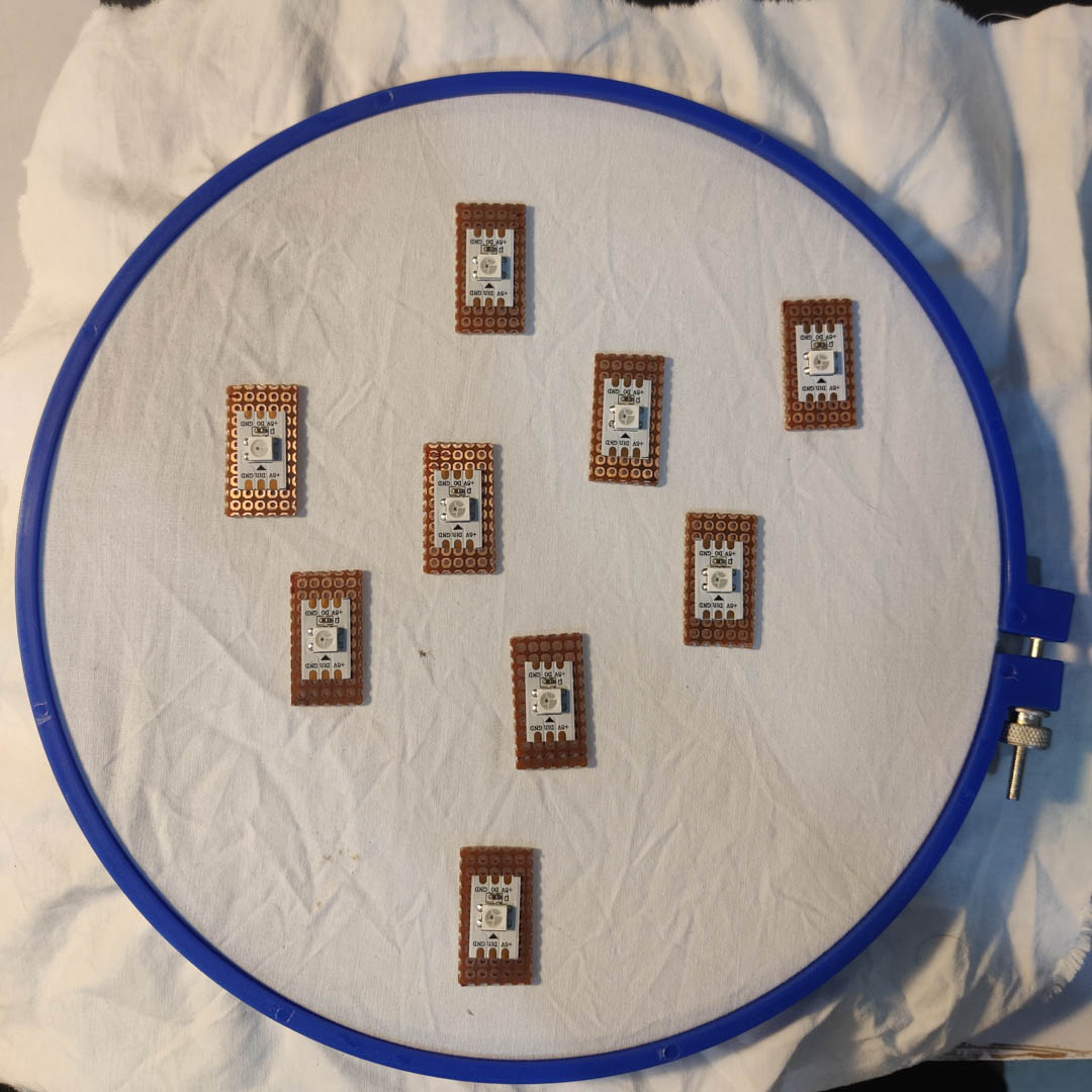
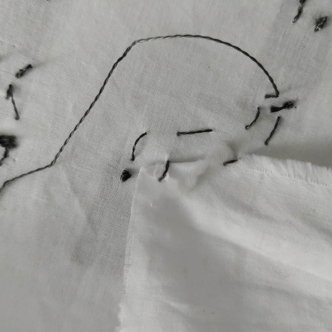
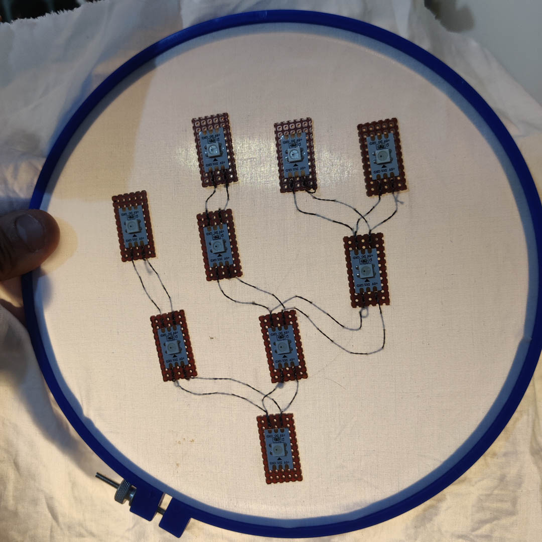
Where thread crossed over other threads, I applied masking tape over the conductive threads to maintain electrical separation.
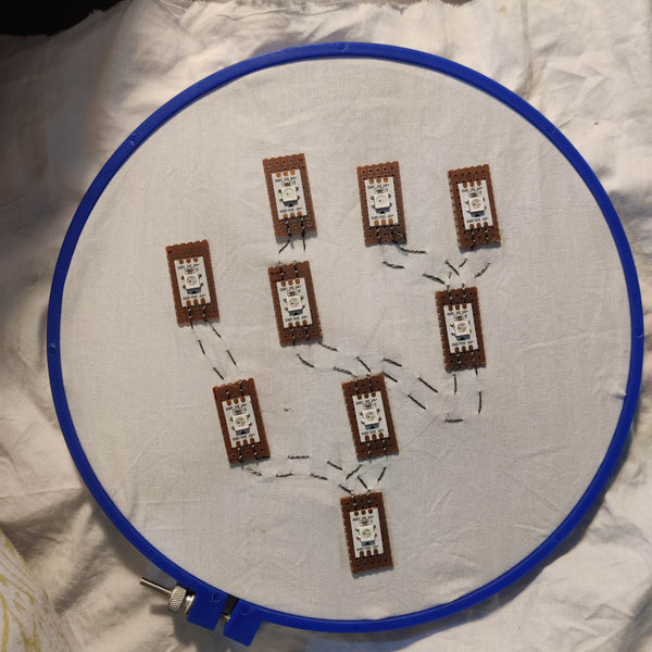
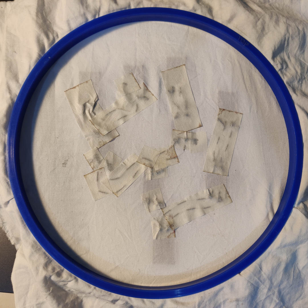
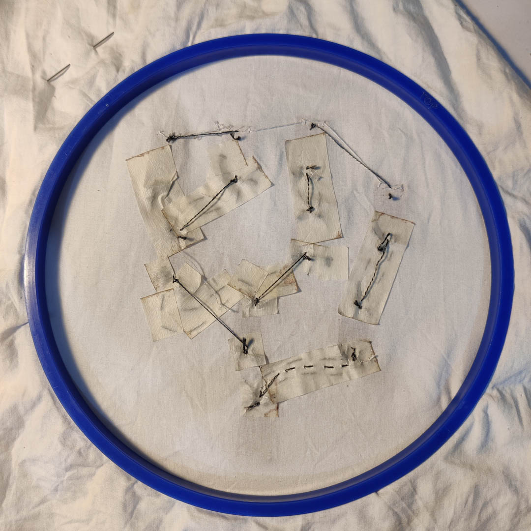
Once the 5V and GND paths were sorted, I ran a third path for the Sig IN and Sig Out pins. While the 55V and GND paths could be branches, parallel or series, the SIG path had to be a series for the neopixels.
Finally I tested my code and wiring on a square panel using an Arduino to make sure there were no issues with the code, before connecting the same base circuit + arduino + code to the Neopixel tree.
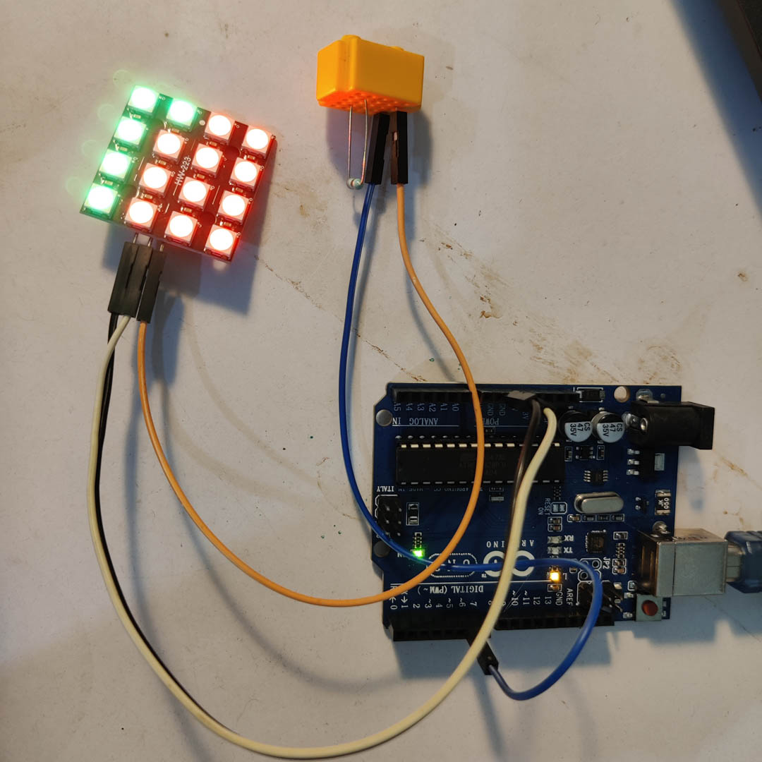
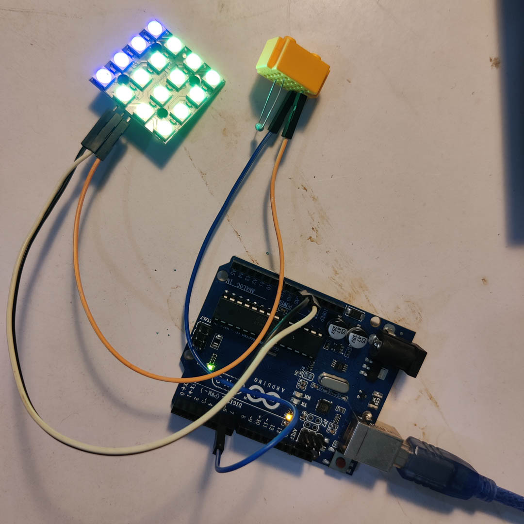
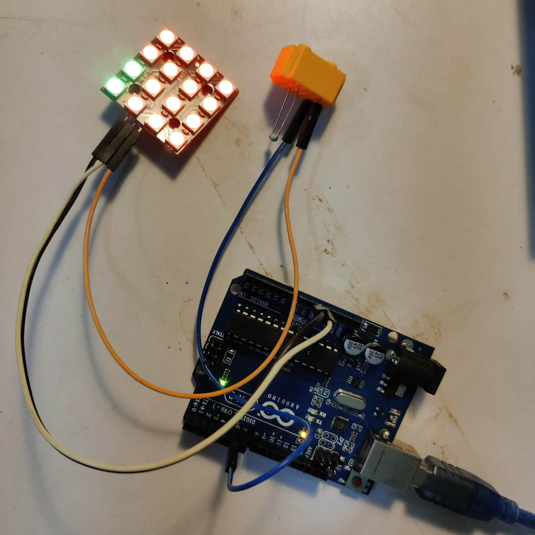
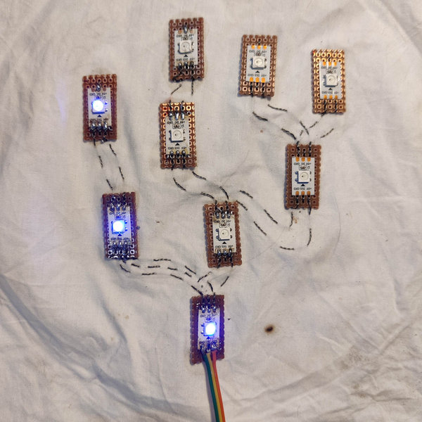
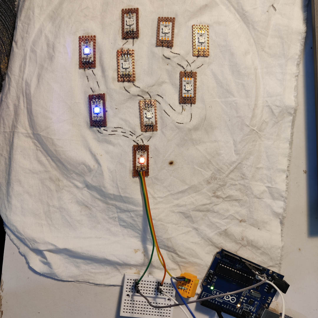
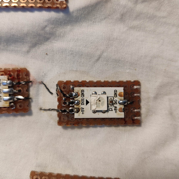
While the code certainly works, there seems ot be something shorting LED 4 and the tree isn't lighting up LED 4 onwards. This needs some reworking and meticulous testing to correct and get it working as intended. However, in principle, it works. It defeintely needs the rest of the process as well - cutting the base fabric to size, adding aglets to make it wearable, and generaly tidying up.
Code for basic Neopixel test :
#include <Adafruit_NeoPixel.h>

#define LED_PIN     6      // Pin connected to the NeoPixel data line
#define LED_COUNT   4      // Number of NeoPixels in the strip

Adafruit_NeoPixel strip(LED_COUNT, LED_PIN, NEO_GRB + NEO_KHZ800);

void setup() {
  strip.begin();           // Initialize the NeoPixel strip
  strip.show();            // Turn OFF all pixels at startup
  strip.setBrightness(100); // (optional) set brightness 0–255
}

void loop() {
  // Simple color cycle: red → green → blue
  colorWipe(strip.Color(255, 0, 0), 100);  // Red
  colorWipe(strip.Color(0, 255, 0), 100);  // Green
  colorWipe(strip.Color(0, 0, 255), 100);  // Blue
}

// Helper function: fill the strip color by color
void colorWipe(uint32_t color, int wait) {
  for (int i = 0; i < strip.numPixels(); i++) {
    strip.setPixelColor(i, color);
    strip.show();
    delay(wait);
  }
}
Issues, Conclusions and Reflections
- A number of fabric based sensors were crafted. Some were successful, some should work in principle but need practical refinement.
- A number of methods to make hard-soft connections were explored.
- I realised stitching is a good but time-consuming process while Cu tape is quick-and-easy, but may not be durable. This is seen in effect in my wearable week where, unlike the considerable conductive thread stitching I did here, I go ahead and use Cu tape extensively.
- Debugging shortcircuits in conductive thread is extremely tiresome - I had to give up and take pause even though the project was a version of something I had already done and so I knew what issues were to be expected.
- however, on the whole, this is a whole new dimension of electronics embedded into textile and soft materials, that I am looking forward to explore.
- the inherent hackyness and use of unexpected properties of random objects also adds to the fun !
Files
Code already inserted across this page.