11. Open Source Hardware - From Fibers to Fabric
weekly assignment
Learning outcomes
- Research skills: the participant has acquired knowledge through references and Concept development
- Design skills: the participant has learnt through sketches, 3D modeling, use of electronics, etc
- Fabrication skills: the participant is capable of executing from file to production workflow, from 3D modelling to digital fabrication, electronics, materials
- Process skills: Anyone can go through the process, understand it and reproduce it
- Final outcome: The assignment is assembled and either complete or tested = Originality: Has the design been thought through and elaborated?
Student checklist
- Research and document existing fabrication methods, machines and industries, add references, tutorials and sketches of the hardware you will make
- Document the process of designing the files for your machine/machine-hack/tool and its fabrication including the assembly process
- Document the schematic and the software source code (if any)
- Document the parts and how to make your tool or machine
- Document your BOM (Bill of materials): electronics, materials, their amount, etcetera (with references of the components)
- Upload your 3D model and CAM files (if any)
- Design, create and document a final outcome, a sample project of your process
- Make a small video of the machine
- Create an interface for controling your machine (extra credit)
Check out the weekly assignment here
Research & Ideation
get inspired!
Check out and research alumni pages to betetr understand how to document and get inspired
-
OS Loom - Kae Nagano - Fab Lab Kamakura
-
The pattern machine - Marion Guillaud - LeTextileLab Lyon
-
Shopbot Hack - Painting machine Asli Aksan - Textile Lab Amsterdam
-
Prusa - Pegboard - Viviane Labelle - EchoFab
-
Final project - Pauline Gamore
References & Inspiration
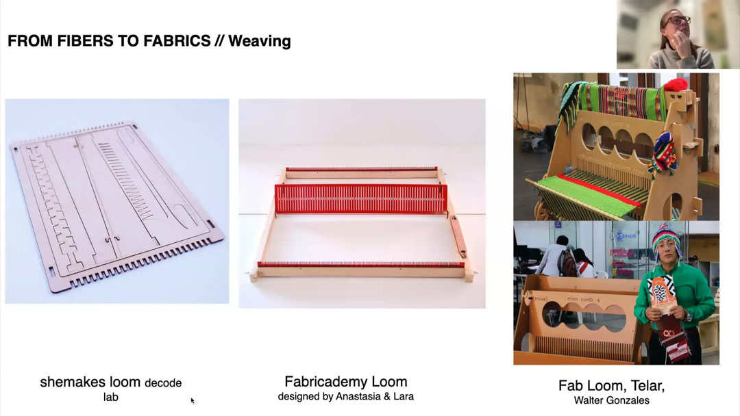 I have long been fascinated by weaving and looms. So the portable loom projects from the Fab and Fabri communities have always been a favourite.
I met Walter in Bhutan at Fab23 and discovered a version of the FabLoom / SheMakes loom in a workshop he was taking, and eventually made one for myself.
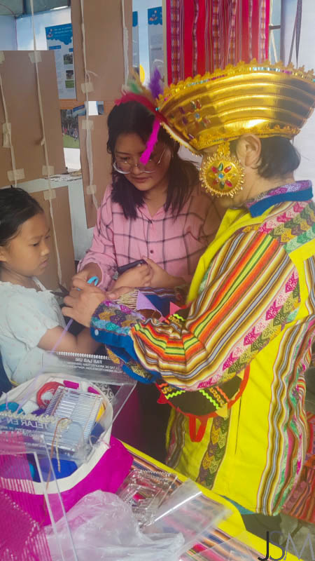
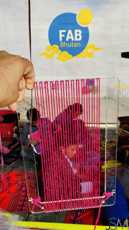
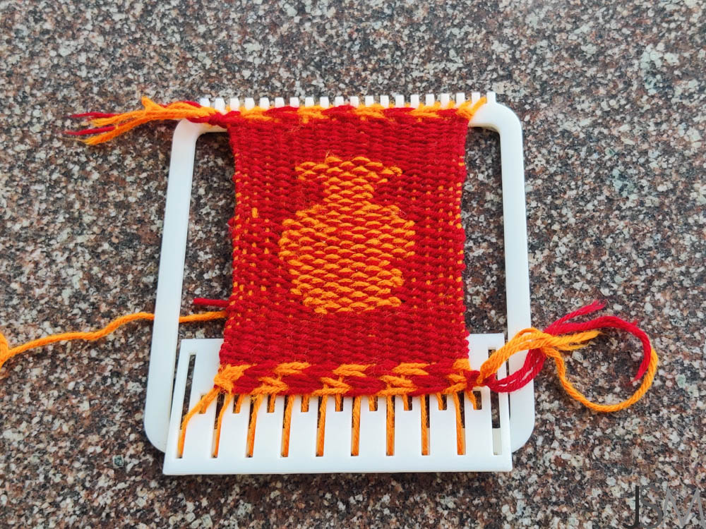
Find the longer version of that story on my Cabinet of Curiosities website.
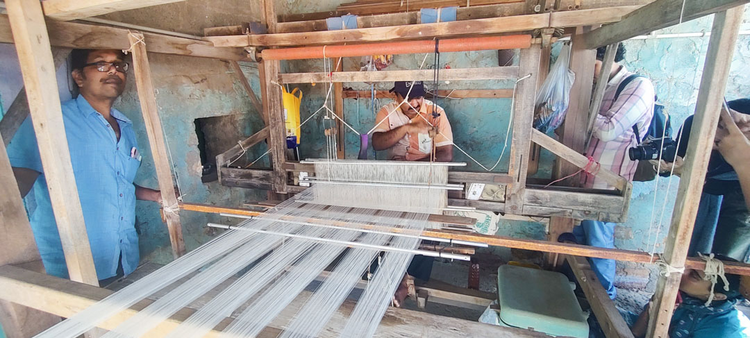
From my visits with the weavers of Kutch as well, I am always enthralled by their work.
Another fantastic open source project I have long been a fan of is the Open Press Project.
Among other things, they have the files, documentation and instructions for open source, 3D printable mini presses.


Beyond these, I found other weaving and braiding machines interesting. Especially interesting in both the main session as well as the tutorial were the software/interface/fileType aspect, because I find too few people address/are inteested in that.
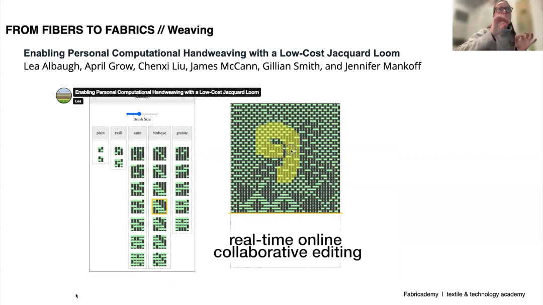
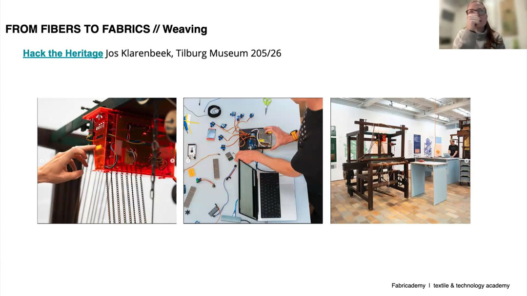
The ability to encode data in knits and weaves is astonishing, and it has been in use for ages. The one that sticks in my mind is that during the French revolution, the common people would record names of the guillotined and the not-yet within their knitting.
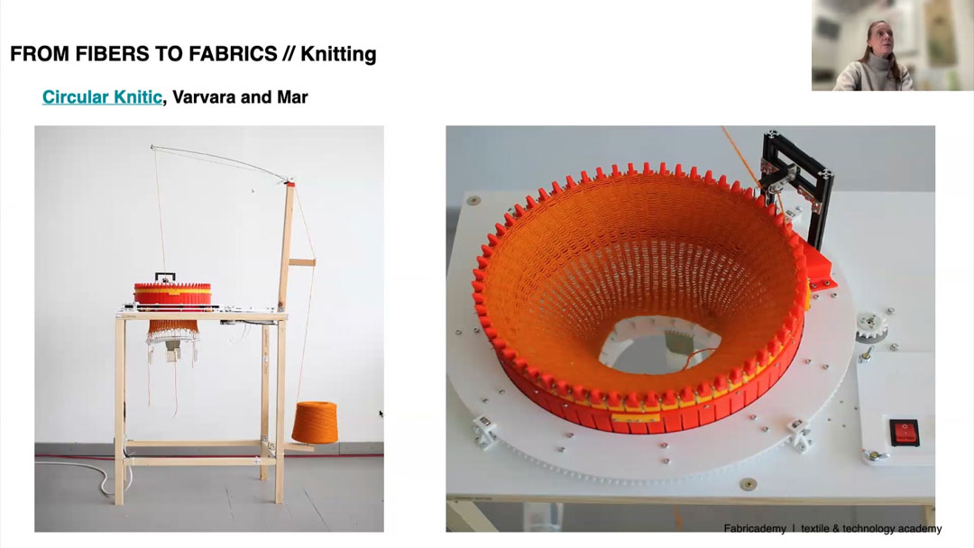
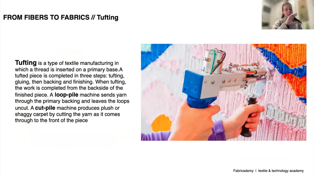
The circular knitting machine is also very interesting, and I've imagined adding a motor to the toy version to run it faster. The Tufting gun is also a popular activity that I'd like to try out.
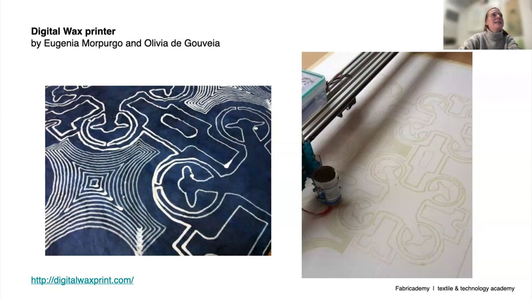
Using a plotter to plot wax lines and do batik is simply brilliant.
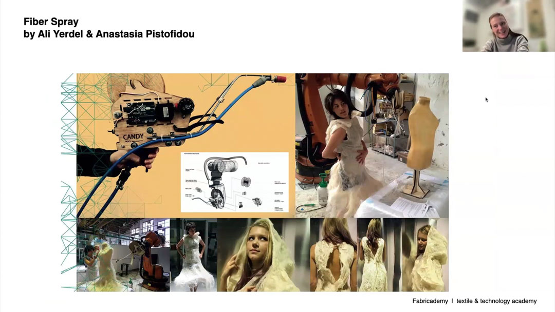
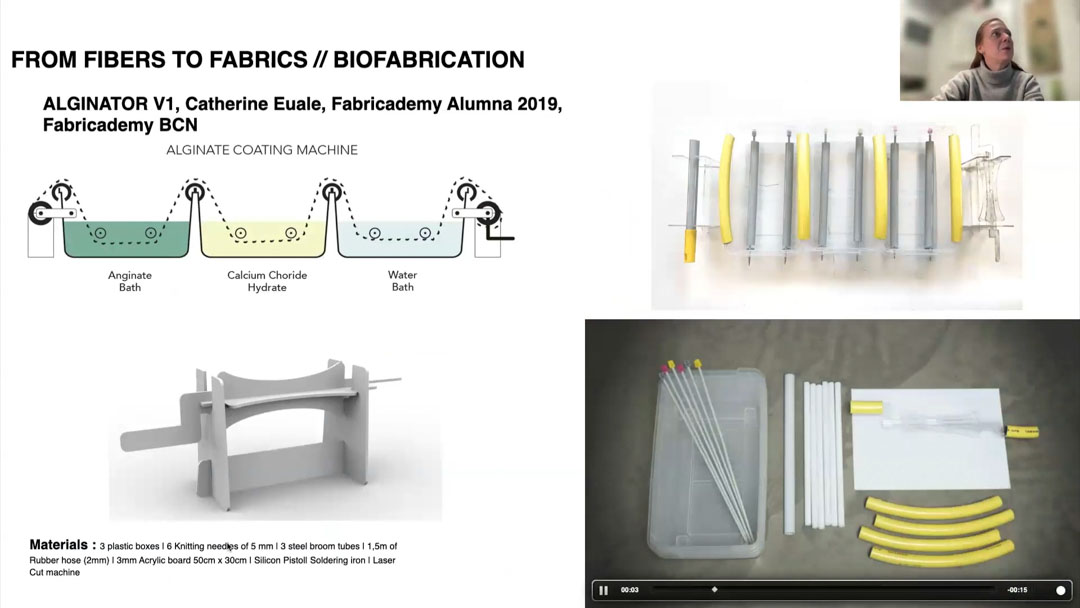
I had some ideas along similar lines during Textile Scaffolding as well. The Fibre Gun looks very interesting to use. The Alginate rollers are a very simple but elegant way to coat and create bio-composites.
Ideation
I had a number of ideas, listed below
- Thread-winder 3D printing / Additive threadwinding - A winding-drum spool that gets contours built on it by depositing thread
- Arduino mini-loom - a programmable pattern loom
- Braiding Machine - Making the Braiding machine would also be very interesting, to then use it with different kinds of fibers and materials, but also to try and work out how to make 3-ply braids, 4-ply braids of different kinds, and higher-order plaiting as well.

- Timelapse camera - a different sort of tool, but one that was equally useful. I have used timelapses for technical stuff like battery life cycle testing, LED thermal management, etc for a while now over the years. Earlier with a webcam on a PC or laptop, then cellphones.
In the course of the Fabricademy program as well, I created a number of timelapses for Digital Bodies, and other assignments using the cellphone.
The problem with cellphone based timelapses is the obvious one - it blocks your cellphone for a long period of time, so you tend to avoid timelapses; you can't use your cellphone for anything else at all, including taking normal pictures; and depending on the software and settings, any incoming calls, notifications, battery loss, etc could interrupt your timelapse and you may not recover any of it. Also, overly long lengths of time are impractical - I would not want my cellphone to be taking a ten hour timelapse. Hence, for long-arc tracking of the growths and decays in biomaterials, crystals, kombucha, as well as the observation of nature around us itself, a dedicated timelapse camera itself seems like a good idea.
Eventually, I did the following
- Additive Threadwinding - attempted, but came up against actual physics so stopped - documented below
- Arduino MiniLoom - attempted - this has been designed, printed, etc but is partially assembled because the design has become too complex at it's size and finicky to complete - on standby for now - documented below
- Timelapse camera - I had started this earlier to use for Fabri, and it has evolved over the months, but this is a usable and complete solution - documented on the next page
Thread Winder - String 3D Printing
Concept
I saw this thread spooling device during our visits to Kutch.
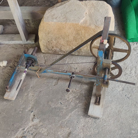
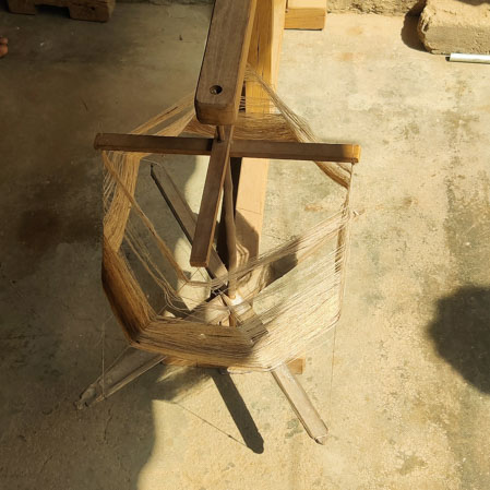
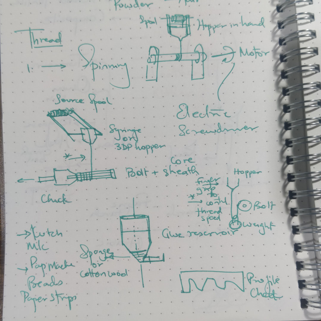
A machine that winds thread on a spindle core; the thread is moistened with glue by passing through a hopper/glue chamber; the thread source moves along one axis to control location of deposition on cylinder; the thread builds up on the core to create a 3d volumetric form, of cylindrical symmetry; ergo, thread 3D printing.
Initial - using basic tools and an electric screwdriver or powerdrill to spin the spindle and manually control the linear direction Final - cylindrical speed control + linear axis control + software to work out thread layers and move linear axis accordingly to deposot more or less thread in a region
Core can be slender - a pencil or bolt - to create forms; Core can be a larger cylinder that cna later be released - to create hollow boxes/containers with decorative outer shells
Use p5.js or other code to create a "spool path" from the input profile that controls the linear location of the source spool.
Trial
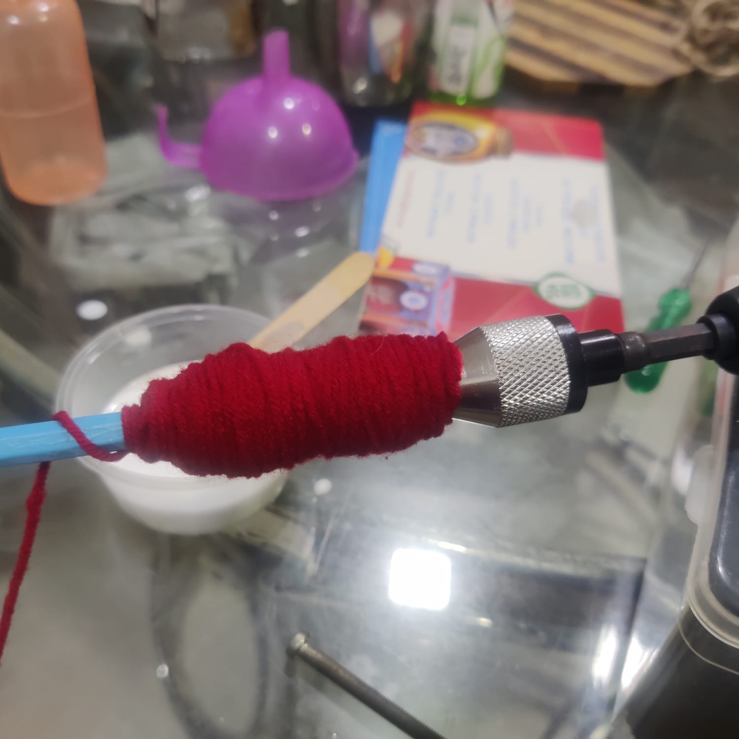
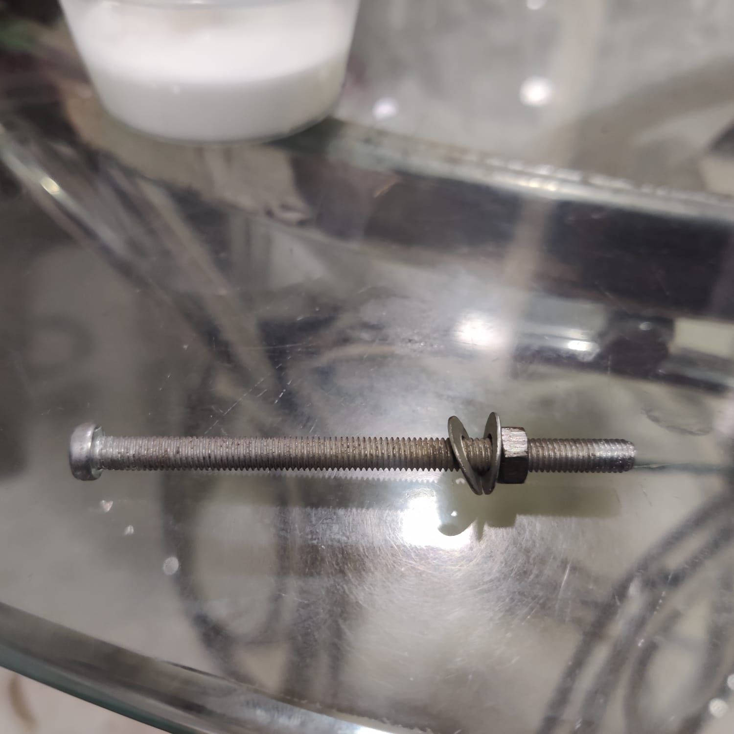
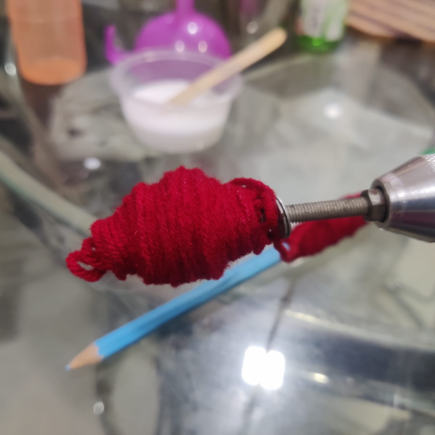
When I tried the manual version, I hit a snag. The contour could not be built, try as I might. I kept the sting source far away, and I brought it up close, but the string landing poing kept wobbling over the surface.
My guess is that there is some kind of "angle of repose" or "heaping angle" effect at play here, that things will roll off beyond a certain angle of steepness. This will effectively prevent it from building any contours.
 Reference : Angle of Repose, Wikipedia
Arduino Loom
Overall Concept
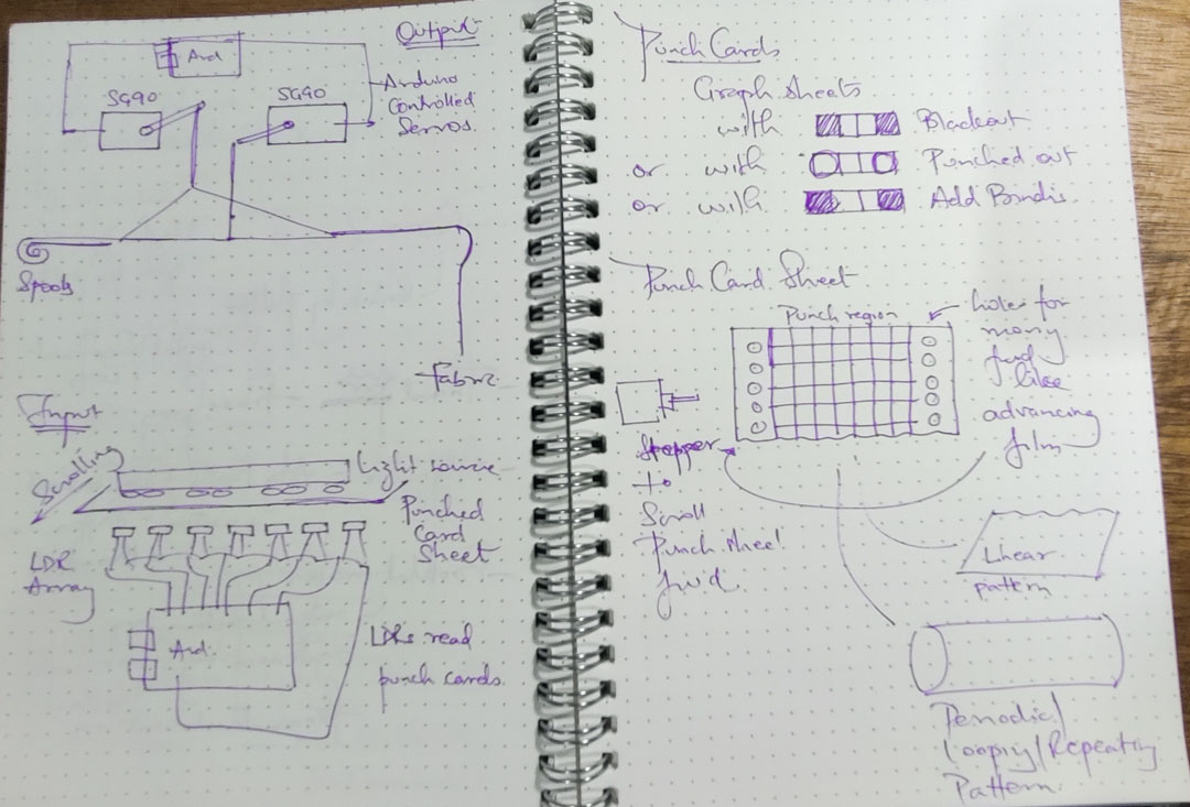
I wanted to begin with a small programmable loom that could be expanded later, rather than trying to build the entire system at once.
The project was divided into two phases:
- Phase 1 focuses on controlling the warp threads electronically using a binary pattern stored in the Arduino code.
- Phase 2 proposes moving the pattern out of the code and encoding it physically using a punch-card strip.
Phase 1 allows me to test:
- Whether individual warp threads could be controlled using small servo motors
- Whether eight servos could be operated from one Arduino Uno
- Whether a binary image could be converted into a usable weaving sequence
- Whether the loom could move through the sequence one row at a time
Phase 2 would build on this by adding:
- A punch-card reader
- LDR sensors
- A light source
- A stepper-driven card-feed mechanism
- A way to change the weaving pattern without editing and uploading the Arduino code each time
Phase 1 - Programmable Mini-Loom
Concept
The first phase focuses on controlling the warp threads electronically:
- The prototype has eight independently controlled warp threads.
- Each warp thread is controlled by one SG90 servo motor.
- The servos move the heddles up or down to create the required shed.
- An Arduino Uno controls the eight servos.
- The weaving pattern is stored as a binary grid:
1moves a servo to the raised position.0moves a servo to the lowered position.- A pushbutton advances the loom to the next row of the pattern.
- The shuttle is passed manually.
- Once the final pattern row is reached, the program loops back to the first row.
Tools
- Arduino UNO
- Arduino IDE
- Fusion 360
- Inkscape
- CorelDRAW
- SIL CO2 lasercutter (110 W, 3x4 feet)
- RDWorks, the associated lasercutter operating software
- Prusa i3 MK3s+
- PrusaSlicer, the associated 3D printing operating software
Mechanical Design
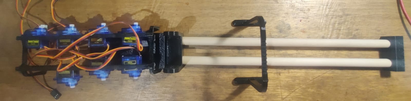
The Phase 1 prototype is based on a small, expandable loom with eight warp channels.
The main mechanical elements are:
- A frame that holds the warp threads in position
- Eight servo motors arranged along the loom
- One servo-controlled heddle connection for each warp thread
- Supports that keep the servos and warp-control mechanism aligned
- A manually operated shuttle for passing the weft
Each servo controls one warp channel:
- One servo position raises the associated heddle or warp thread.
- The opposite servo position lowers it.
- The combination of raised and lowered threads creates the shed for each row.
- The shuttle is then passed manually through the shed.
The loom was kept small so that I could first test the heddle-control mechanism.
The number of warp threads can later be increased by:
- Adding more servo positions
- Widening the frame
- Adding additional controller boards
- Dividing the loom into repeated eight-channel modules
Electronics
The Phase 1 electronics consist of:
- 1 Arduino Uno
- 8 SG90 servo motors
- 1 momentary pushbutton
- Wiring between the Arduino, servos and button
- A power source for the Arduino and servo motors
The eight servo signal pins used in the current code are:
- Servo 1 - Pin 3
- Servo 2 - Pin 5
- Servo 3 - Pin 6
- Servo 4 - Pin 9
- Servo 5 - Pin 10
- Servo 6 - Pin 11
- Servo 7 - Pin 12
- Servo 8 - Pin 13
The pushbutton is connected to:
- Pin 2
- Ground when pressed
- The Arduino's internal pull-up resistor using
INPUT_PULLUP
The servo positions are currently defined as:
90°- neutral position180°- raised position0°- lowered position
Coding
Pattern Generator
I used p5.js to convert an image into a binary weaving pattern.
The pattern generator:
- Loads an image
- Resizes it to a smaller grid
- Reads the RGB value of every grid cell
- Calculates its average brightness
- Compares the brightness against a threshold value
- Converts the cell into either
1or0 - Stores the values as a two-dimensional array
- Displays a pixelated preview of the result
- Prints the binary array to the browser console
The threshold controls which pixels become raised or lowered warp threads:
- Pixels darker than the threshold become
1. - Pixels lighter than the threshold become
0.
The resulting array can then be copied into the Arduino sketch as the loom pattern.
For the current eight-thread prototype:
- The number of columns should be set to
8. - Each column corresponds to one servo and one warp thread.
- The number of rows can vary depending on the length of the pattern.
Pattern Generator Code
Pattern Generator in p5.js
let weaveImage = "myImage.jpg";
let cols = 8;
let rows = 8;
let threshold = 128;

let img;
let weavePattern;

function preload() {
  img = loadImage(weaveImage);
}

function setup() {
  createCanvas(img.width, img.height);
  noLoop();

  // Make a copy and shrink it to grid size
  let small = img.get();   // copy to preserve original
  small.resize(cols, rows);  // resize image to grid

  // Generate 1/0 pattern
  small.loadPixels();
  weavePattern = [];

  for (let y = 0; y < rows; y++) {
    let row = [];
    for (let x = 0; x < cols; x++) {
      let idx = 4 * (y * small.width + x);
      let r = small.pixels[idx + 0];
      let g = small.pixels[idx + 1];
      let b = small.pixels[idx + 2];
      let bright = (r + g + b) / 3;
      row.push(bright < threshold ? 1 : 0);
    }
    weavePattern.push(row);
  }

  console.log("Weave pattern:", weavePattern);
  drawPixelated(weavePattern);
}

// Preview - unchanged
function drawPixelated(grid) {
  background(255);
  let cellW = width / cols;
  let cellH = height / rows;
  noStroke();
  for (let y = 0; y < rows; y++) {
    for (let x = 0; x < cols; x++) {
      fill(grid[y][x] === 1 ? 0 : 255);
      rect(x * cellW, y * cellH, cellW, cellH);
    }
  }
}
Arduino Servo Control
The Arduino program controls the eight servos and moves through the weaving pattern one row at a time.
The program:
- Includes the Arduino
Servolibrary - Creates an array of eight servo objects
- Defines the pin used by each servo
- Stores the weaving pattern as a two-dimensional binary array
- Moves all servos to their neutral positions during setup
- Uses a pushbutton to advance the pattern
- Debounces the pushbutton to avoid multiple accidental triggers
- Reads the next row of the pattern
- Moves each servo to either the up or down angle
- Loops back to the first row after the final row
The basic sequence is:
- Press the button.
- Advance to the next row.
- Read the eight binary values in that row.
- Move the corresponding servos.
- Pass the shuttle manually.
- Press the button again for the next row.
Arduino Code
Arduino Code for loom
#include <Servo.h>

//  CONFIGURATION
const byte NUM_SERVOS = 8;
const byte NUM_ROWS   = 8;  // number of rows in the pattern

// Pins for the 8 servos
const byte servoPins[NUM_SERVOS] = {3, 5, 6, 9, 10, 11, 12, 13};

// Button pin
const byte buttonPin = 2;  // wired to GND when pressed, with INPUT_PULLUP

// Servo angles
const int NEUTRAL_ANGLE = 90;
const int UP_ANGLE      = 180;  // 90° forward from neutral
const int DOWN_ANGLE    = 0;    // 90° backward from neutral

// Debounce
const unsigned long DEBOUNCE_MS = 50;

//  PATTERN (BINARY GRID)
// 1 = move servo to UP_ANGLE
// 0 = move servo to DOWN_ANGLE
const byte weavePattern[NUM_ROWS][NUM_SERVOS] = {
  {0, 0, 0, 1, 1, 0, 0, 0},
  {0, 0, 1, 1, 1, 1, 0, 0},
  {0, 1, 1, 0, 0, 1, 1, 0},
  {1, 1, 0, 0, 0, 0, 1, 1},
  {1, 1, 0, 0, 0, 0, 1, 1},
  {0, 1, 1, 0, 0, 1, 1, 0},
  {0, 0, 1, 1, 1, 1, 0, 0},
  {0, 0, 0, 1, 1, 0, 0, 0}
};

//  GLOBALS
Servo servos[NUM_SERVOS];

int currentRow = -1;            // starts at -1 so first tap moves to row 0
bool lastButtonState = HIGH;    // because of INPUT_PULLUP
unsigned long lastDebounceTime = 0;

//  SETUP
void setup() {
  // Attach servos and move them to neutral
  for (byte i = 0; i < NUM_SERVOS; i++) {
    servos[i].attach(servoPins[i]);
    servos[i].write(NEUTRAL_ANGLE);
  }

  // Button with internal pullup
  pinMode(buttonPin, INPUT_PULLUP);

  // Optional: for debugging over serial
  Serial.begin(9600);
  Serial.println("Servo weave pattern ready. Tap switch to step rows.");
}

//  LOOP
void loop() {
  // Read the button
  bool reading = digitalRead(buttonPin);

  // Debounce logic
  if (reading != lastButtonState) {
    lastDebounceTime = millis();
  }

  if ((millis() - lastDebounceTime) > DEBOUNCE_MS) {
    static bool lastStableState = HIGH;
    if (reading != lastStableState) {
      lastStableState = reading;

      if (reading == LOW) {
        advanceRowAndMoveServos();
      }
    }
  }

  lastButtonState = reading;
}

//  FUNCTIONS

// Advance to the next row of the binary grid and move all 8 servos
void advanceRowAndMoveServos() {
  // Move to next row (wrap around)
  currentRow = (currentRow + 1) % NUM_ROWS;

  Serial.print("Moving to row ");
  Serial.println(currentRow);

  // For each servo/column in this row:
  for (byte col = 0; col < NUM_SERVOS; col++) {
    byte bit = weavePattern[currentRow][col];

    int targetAngle;
    if (bit == 1) {
      targetAngle = UP_ANGLE;
    } else {
      targetAngle = DOWN_ANGLE;
    }

    servos[col].write(targetAngle);
  }

  delay(20);
}
Fabrication and Assembly
Calibration and Operation
Testing and Iterations
Final Outcome
Phase 2 - Punch-Card-Controlled Loom
Proposed Concept
The eventual aim is to move the pattern out of the Arduino code and encode it physically using a punch-card strip.
The proposed system would work as follows:
- A row of holes in the punch card represents one row of the weaving pattern.
- Each warp thread has a corresponding LDR sensor.
- A light source is placed above the punch card.
- Light passes through the punched holes and reaches the LDRs below.
- The Arduino reads the LDR values and converts the physical row into a binary pattern.
- The Arduino then moves each servo either up or down.
- After the shuttle has been passed, the card advances to the next row.
- A stepper motor would move the punch card forward by one step.
The punch-card strip could be:
- Punched manually
- Laser cut
- Used as a linear strip
- Joined into a loop for repeating patterns
This phase would make the loom programmable without needing to edit and upload the Arduino code each time.
Proposed Mechanical Design
Phase 2 adds a physical punch-card reader to the existing loom.
The proposed mechanical additions are:
- A punch-card strip positioned between the light source and the LDR sensors
- A row of eight sensing positions aligned with the eight warp channels
- Feed wheels or sprockets that engage with the edges of the punch-card strip
- A stepper motor that advances the strip one row at a time
- Guides that keep the punch card aligned with the sensors
- A removable or hinged section that allows the pattern strip to be loaded
The punch-card feed must:
- Move by exactly one pattern row after each weaving cycle
- Hold the card flat while it is being read
- Prevent light from leaking between adjacent sensing positions
- Work with either a linear strip or a repeating loop
Proposed Electronics
For each warp channel, Phase 2 requires:
- 1 servo motor already present from Phase 1
- 1 LDR sensor
- 1 fixed resistor for the LDR voltage divider
- 1 corresponding position on the punch card
For eight warp threads, this gives:
- 8 servo control signals
- 8 LDR readings
- Stepper-motor control signals
- An input to confirm that the shuttle has been passed and the system can advance
This makes the available pins on an Arduino Uno quite limited.
Possible ways to expand the system include:
- Using an Arduino Mega
- Using an I²C servo-driver module such as a PCA9685
- Using additional microcontrollers as repeated eight-channel modules
- Connecting the secondary controllers to a main controller through I²C
- Using an analogue multiplexer if more sensor inputs are required
The Phase 2 electronics would also require:
- A stepper motor
- A compatible stepper-motor driver
- A light source above the punch card
- Eight LDR voltage-divider circuits
- A method of shielding each LDR from neighbouring light
- A suitable power supply for the servos, lights and stepper motor
Proposed Coding and Control Sequence
The Phase 2 code has not yet been developed.
The proposed program would:
- Read the eight LDR sensor values.
- Compare each value against a calibrated light threshold.
- Convert the sensor readings into eight binary values.
- Move the corresponding eight servos.
- Wait for confirmation that the shuttle has been passed.
- Move the punch card forward by one row.
- Wait for the card and sensors to settle.
- Read the next pattern row.
- Repeat the process.
Additional code would be needed for:
- Calibrating the LDR values
- Compensating for differences between individual sensors
- Controlling the stepper motor
- Preventing the card from advancing more than one row
- Detecting the beginning and end of a linear card
- Repeating a pattern when a looped card is used
- Communicating between multiple Arduino boards
- Controlling the servos through an I²C servo-driver module
- Reporting the current row and sensor readings through the Serial Monitor
Expansion and Scalability
The Phase 2 system could later be expanded by:
- Increasing the number of warp channels
- Using repeated eight-channel servo and sensor modules
- Using a larger controller
- Separating servo control and sensor reading across multiple boards
- Connecting secondary controllers through I²C
- Using looped cards for repeating patterns
- Using longer linear cards for non-repeating patterns
Next Steps
The next steps for Phase 2 would be:
- Test one LDR with a punched card
- Test light shielding between adjacent sensing positions
- Decide the punch-card row and column spacing
- Design the card guides and feed wheels
- Select a stepper motor and driver
- Test one-row card advancement
- Finalise the controller and pin arrangement
- Develop the sensor-calibration code
- Integrate the card reader with the existing servo loom
- Test a complete repeating pattern
Bill of Materials
Phase 1 - Components Used
Bill of Materials
Arduino Loom - Current Prototype
| Category | Component / Material | Specification | Quantity | Purpose / Notes |
|---|---|---|---|---|
| Electronics | Arduino Uno | ATmega328P development board | 1 | Controls the eight servo motors and reads the pushbutton input |
| Electronics | Micro servo motors | SG90, 9 g, 180° | 8 | One servo independently raises or lowers each warp thread |
| Electronics | Momentary pushbutton | Normally open tactile or panel-mount switch | 1 | Advances the loom to the next row of the programmed pattern |
| Electronics | Jumper wires | Male–male and/or male–female | 1 set | Connections between the Arduino, servos and pushbutton |
| Electronics | Servo extension wires | Three-core servo extensions, if required | 8 | Allows the servos to reach the controller without straining their leads |
| Electronics | 5 V power supply | Regulated supply, approximately 3 A | 1 | External power for the eight servos; the servo supply and Arduino must share a common ground |
| Electronics | USB cable | USB-A to USB-B | 1 | Programming and serial communication with the Arduino |
| Mechanical | Servo horns | Supplied with SG90 servos | 8 | Connect the servo shafts to the heddle or warp-control strings |
| Mechanical | Servo mounting screws | Supplied with the servos or equivalent | 16 | Two screws per servo for fixing the servos to the frame |
| Mechanical | Laser-cut base and frame pieces | Sheet material; type and thickness to be confirmed | 1 set | Holds and aligns the servos and loom mechanism |
| Mechanical | 3D-printed mounting components | PLA or equivalent filament | 1 set | Servo supports, rod holders, end brackets and connecting components |
| Mechanical | Parallel rods / dowels | Diameter and length to be measured from the prototype | 2 | Form the principal longitudinal structure of the loom |
| Mechanical | General fasteners | Nuts, bolts, washers and/or self-tapping screws | 1 set | Assembly of the frame and printed components; sizes to be confirmed |
| Loom components | Warp-control cords | Strong thread or fine cord | 8 lengths | Connect each servo horn to its corresponding warp thread or heddle |
| Loom components | Warp yarn | Suitable weaving yarn | 8 ends minimum | Eight independently controlled warp threads in the current prototype |
| Loom components | Weft yarn | Suitable weaving yarn | 1 spool | Passed manually through the shed |
| Loom components | Manual shuttle | Fabricated, purchased or improvised | 1 | Carries the weft yarn through the warp |
| Consumables | 3D-printing filament | PLA or equivalent | As required | Used to fabricate the printed structural components |
| Consumables | Adhesive | Hot glue, cyanoacrylate or equivalent | As required | Secures components where mechanical fastening is not used |
| Consumables | Cable ties / fastening wire | Small size | As required | Cable management and strain relief |
Phase 2 - Additional Components Proposed
| Category | Component / Material | Specification | Quantity | Purpose / Notes |
|---|---|---|---|---|
| Sensors | Light-dependent resistors | Standard LDR / photoresistor | 8 | Reads one punch-card position for each warp channel |
| Sensors | Fixed resistors | Value selected for LDR voltage dividers | 8 | Converts each LDR resistance into an analogue voltage |
| Lighting | LED light sources | White LEDs or LED strip | 8 or 1 strip | Illuminates the punch-card openings above the LDR array |
| Electronics | Servo driver board | PCA9685, 16-channel I²C | 1 | Optional expansion board for controlling multiple servos |
| Motion | Stepper motor | Size to be selected | 1 | Advances the punch-card strip |
| Motion | Stepper motor driver | Compatible with selected motor | 1 | Interfaces the stepper motor with the microcontroller |
| Mechanical | Punch-card feed wheels | 3D printed or laser cut | 1 set | Engages and advances the perforated pattern strip |
| Pattern medium | Punch-card strip | Paper, card or thin plastic sheet | As required | Stores linear or repeating weaving patterns |
Gallery
Video
Fabrication and Source Files
Phase 1 Files
- 3D models
- Laser-cut files
- Arduino
.inofile - p5.js pattern-generator files
- Pattern image or sample file
Proposed Phase 2 Files
- Punch-card layout
- Card-reader design files
- Feed-wheel design
- Proposed circuit diagram
- Proposed control-flow diagram
Arduino Loom
Concept
A mini-loom, expandable as needed. Servos control the heddles moving up and down; Arduino or othe uP controls the servos; Arduino gets input from either code or sensor; Sensor is LDR with Lightsource above; LDR is triggered by punch cards !
Punch card patterns -> read by LDR to Arduino -> which controls individual servos up or down
Shuttle is manual.
Punch card sheet like photography film, engaged in gear teeth, will move forward by a step using a stepper motor.
Punch card sheet can be manually filled or lasercut, linear or looping.
Kae Nagano's OS loom is a good reference for me, but I am also automating the heddles by using servo motors, and in phase 2 I want to add sensor input for the "punch card" patterns.
Analyses :
For 1 thread of warp :
- 1 servo motor SG90
- 1 LDR
Therefore for a 13+5=18 pin Arduino Uno, 8 warp threads = 8 servo signals + 8 LDR readings = 16 pins 1 signal to control stepper = 1 pin 1 signal to take input to move stepper and servos after shuttle has been shuttled
Additional uPs can be daisy chained, 8-9 threads per Arduino Uno since other boards can simply work in parallel, take I2C signal from mainboard.
Maybe try a Mega later ?
Get an I2C servo driver module ?
Trial
Tools
- Arduino UNO
- Arduino IDE
- Fusion 360
- Inkscape
- CorelDRAW
- SIL CO2 lasercutter (110 W, 3x4 feet)
- RDWorks, the associated lasercutter operating software
- Prusa i3 MK3s+
- PrusaSlicer, the associated 3D printing operating software
3D Models
Materials
Process
BoM
Bill of Materials
Arduino Loom - Current Prototype
| Category | Component / Material | Specification | Quantity | Purpose / Notes |
|---|---|---|---|---|
| Electronics | Arduino Uno | ATmega328P development board | 1 | Controls the eight servo motors and reads the pushbutton input |
| Electronics | Micro servo motors | SG90, 9 g, 180° | 8 | One servo independently raises or lowers each warp thread |
| Electronics | Momentary pushbutton | Normally open tactile or panel-mount switch | 1 | Advances the loom to the next row of the programmed pattern |
| Electronics | Jumper wires | Male–male and/or male–female | 1 set | Connections between the Arduino, servos and pushbutton |
| Electronics | Servo extension wires | Three-core servo extensions, if required | 8 | Allows the servos to reach the controller without straining their leads |
| Electronics | 5 V power supply | Regulated supply, approximately 3 A | 1 | External power for the eight servos; the servo supply and Arduino must share a common ground |
| Electronics | USB cable | USB-A to USB-B | 1 | Programming and serial communication with the Arduino |
| Mechanical | Servo horns | Supplied with SG90 servos | 8 | Connect the servo shafts to the heddle or warp-control strings |
| Mechanical | Servo mounting screws | Supplied with the servos or equivalent | 16 | Two screws per servo for fixing the servos to the frame |
| Mechanical | Laser-cut base and frame pieces | Sheet material; type and thickness to be confirmed | 1 set | Holds and aligns the servos and loom mechanism |
| Mechanical | 3D-printed mounting components | PLA or equivalent filament | 1 set | Servo supports, rod holders, end brackets and connecting components |
| Mechanical | Parallel rods / dowels | Diameter and length to be measured from the prototype | 2 | Form the principal longitudinal structure of the loom |
| Mechanical | General fasteners | Nuts, bolts, washers and/or self-tapping screws | 1 set | Assembly of the frame and printed components; sizes to be confirmed |
| Loom components | Warp-control cords | Strong thread or fine cord | 8 lengths | Connect each servo horn to its corresponding warp thread or heddle |
| Loom components | Warp yarn | Suitable weaving yarn | 8 ends minimum | Eight independently controlled warp threads in the current prototype |
| Loom components | Weft yarn | Suitable weaving yarn | 1 spool | Passed manually through the shed |
| Loom components | Manual shuttle | Fabricated, purchased or improvised | 1 | Carries the weft yarn through the warp |
| Consumables | 3D-printing filament | PLA or equivalent | As required | Used to fabricate the printed structural components |
| Consumables | Adhesive | Hot glue, cyanoacrylate or equivalent | As required | Secures components where mechanical fastening is not used |
| Consumables | Cable ties / fastening wire | Small size | As required | Cable management and strain relief |
Planned Punch-card Reader - Not Used in the Current Prototype
| Category | Component / Material | Specification | Quantity | Purpose / Notes |
|---|---|---|---|---|
| Sensors | Light-dependent resistors | Standard LDR / photoresistor | 8 | Reads one punch-card position for each warp channel |
| Sensors | Fixed resistors | Value selected for LDR voltage dividers | 8 | Converts each LDR resistance into an analogue voltage |
| Lighting | LED light sources | White LEDs or LED strip | 8 or 1 strip | Illuminates the punch-card openings above the LDR array |
| Electronics | Servo driver board | PCA9685, 16-channel I²C | 1 | Optional expansion board for controlling multiple servos |
| Motion | Stepper motor | Size to be selected | 1 | Advances the punch-card strip |
| Motion | Stepper motor driver | Compatible with selected motor | 1 | Interfaces the stepper motor with the microcontroller |
| Mechanical | Punch-card feed wheels | 3D printed or laser cut | 1 set | Engages and advances the perforated pattern strip |
| Pattern medium | Punch-card strip | Paper, card or thin plastic sheet | As required | Stores linear or repeating weaving patterns |
Code
Pattern Generator in p5.js
let weaveImage = "myImage.jpg";
let cols = 16;
let rows = 16;
let threshold = 128;

let img;
let weavePattern;

function preload() {
  img = loadImage(weaveImage);
}

function setup() {
  createCanvas(img.width, img.height);
  noLoop();

  // Make a copy and shrink it to grid size
  let small = img.get();   // copy to preserve original
  small.resize(cols, rows);  // resize image to grid

  // Generate 1/0 pattern
  small.loadPixels();
  weavePattern = [];

  for (let y = 0; y < rows; y++) {
    let row = [];
    for (let x = 0; x < cols; x++) {
      let idx = 4 * (y * small.width + x);
      let r = small.pixels[idx + 0];
      let g = small.pixels[idx + 1];
      let b = small.pixels[idx + 2];
      let bright = (r + g + b) / 3;
      row.push(bright < threshold ? 1 : 0);
    }
    weavePattern.push(row);
  }

  console.log("Weave pattern:", weavePattern);
  drawPixelated(weavePattern);
}

// Preview - unchanged
function drawPixelated(grid) {
  background(255);
  let cellW = width / cols;
  let cellH = height / rows;
  noStroke();
  for (let y = 0; y < rows; y++) {
    for (let x = 0; x < cols; x++) {
      fill(grid[y][x] === 1 ? 0 : 255);
      rect(x * cellW, y * cellH, cellW, cellH);
    }
  }
}
Arduino Code for loom
#include <Servo.h>

//  CONFIGURATION
const byte NUM_SERVOS = 8;
const byte NUM_ROWS   = 8;  // number of rows in the pattern

// Pins for the 8 servos
const byte servoPins[NUM_SERVOS] = {3, 5, 6, 9, 10, 11, 12, 13};

// Button pin
const byte buttonPin = 2;  // wired to GND when pressed, with INPUT_PULLUP

// Servo angles
const int NEUTRAL_ANGLE = 90;
const int UP_ANGLE      = 180;  // 90° forward from neutral
const int DOWN_ANGLE    = 0;    // 90° backward from neutral

// Debounce
const unsigned long DEBOUNCE_MS = 50;

//  PATTERN (BINARY GRID)
// 1 = move servo to UP_ANGLE
// 0 = move servo to DOWN_ANGLE
const byte weavePattern[NUM_ROWS][NUM_SERVOS] = {
  {0, 0, 0, 1, 1, 0, 0, 0},
  {0, 0, 1, 1, 1, 1, 0, 0},
  {0, 1, 1, 0, 0, 1, 1, 0},
  {1, 1, 0, 0, 0, 0, 1, 1},
  {1, 1, 0, 0, 0, 0, 1, 1},
  {0, 1, 1, 0, 0, 1, 1, 0},
  {0, 0, 1, 1, 1, 1, 0, 0},
  {0, 0, 0, 1, 1, 0, 0, 0}
};

//  GLOBALS
Servo servos[NUM_SERVOS];

int currentRow = -1;            // starts at -1 so first tap moves to row 0
bool lastButtonState = HIGH;    // because of INPUT_PULLUP
unsigned long lastDebounceTime = 0;

//  SETUP
void setup() {
  // Attach servos and move them to neutral
  for (byte i = 0; i < NUM_SERVOS; i++) {
    servos[i].attach(servoPins[i]);
    servos[i].write(NEUTRAL_ANGLE);
  }

  // Button with internal pullup
  pinMode(buttonPin, INPUT_PULLUP);

  // Optional: for debugging over serial
  Serial.begin(9600);
  Serial.println("Servo weave pattern ready. Tap switch to step rows.");
}

//  LOOP
void loop() {
  // Read the button
  bool reading = digitalRead(buttonPin);

  // Debounce logic
  if (reading != lastButtonState) {
    lastDebounceTime = millis();
  }

  if ((millis() - lastDebounceTime) > DEBOUNCE_MS) {
    static bool lastStableState = HIGH;
    if (reading != lastStableState) {
      lastStableState = reading;

      if (reading == LOW) {
        advanceRowAndMoveServos();
      }
    }
  }

  lastButtonState = reading;
}

//  FUNCTIONS

// Advance to the next row of the binary grid and move all 8 servos
void advanceRowAndMoveServos() {
  // Move to next row (wrap around)
  currentRow = (currentRow + 1) % NUM_ROWS;

  Serial.print("Moving to row ");
  Serial.println(currentRow);

  // For each servo/column in this row:
  for (byte col = 0; col < NUM_SERVOS; col++) {
    byte bit = weavePattern[currentRow][col];

    int targetAngle;
    if (bit == 1) {
      targetAngle = UP_ANGLE;
    } else {
      targetAngle = DOWN_ANGLE;
    }

    servos[col].write(targetAngle);
  }

  delay(20);
}
Conclusion
This build is on hold for the time being. The tensioning of the individual strands makes assembly finicky, and I would like to redesign this to be better instead of forcing a bad build.
Instead, the RasPi Timelapse camera here is the final result for this week.