10. Open Source Hardware- From fibers to fabric
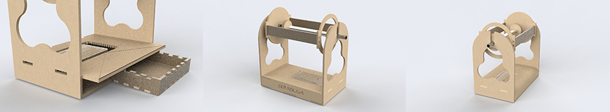
This week we worked as a group to build the HILO 2.0 spinning machine and then decided to design a new spinning machine, with an embedded mini loom and some mini tools for weaving, the Ursula 4.0!!!
This week's assignment:
-Research and document existing fabrication methods, machines and industries , add references and sketches of the machine and the chosen process
-Design and document the files of the machine, machine hack or tool and fabrication - assembly process
-Document the schematic and the programming code (if any)
-List the materials: electronics, materials amount other (references of the components)
-Design, create and document a final outcome, a sample project of your process
-Make a small video of the machine
-Create an interface for controling your machine
Research, inspiration and open source fibre to textile and hacking machines
Updating the industry with new tools, democratizing machines
Knitic Circular knitic Open knit -> kniterate
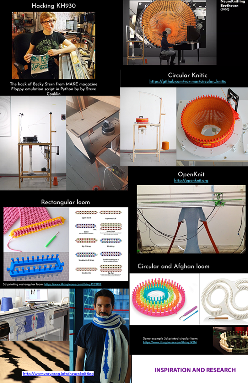
Some really inspiring works as presented in the Open source Hardware lecture as a moodboard
After doing some research, I was also really inspired by Lara Campos's work and process of spinning impregnated fibres with chia seeds and then weaving the fabric on her other custom made tool, a table loom. The result is beautiful and its amazing to see how a little open source spinning machine can help designers and artists to create their own textiles! <3
Chia seeds yarn from Lara Campos on Vimeo.
STUDIO HILO, open technologies and open source spinning HILO MACHINE
Studio HILO is a Berlin-based studio for textile innovation. We rethink the textile industry by offering open tools and expertise for small-scale textile manufacturing environments. HILO’s mission is to create playgrounds for independent yarn production. By sharing our knowledge, we empower designers, researchers and producers to redefine their manufacturing processes from material choice to textile construction and production facilities.
HILO from Studio HILO on Vimeo.
Studio HILO’s open-source projects challenge the process of textile production in the same way 3-D printers revolutionised manufacturing. Open knowledge on textile hardware and software enables experimentation, innovation and rapid prototyping for local yarn manufacturing.
What is the HILO Spinning machine?
The open-source HILO Spinning Machine allows you to produce your own customized yarn. The open-source HILO Software helps you to design the yarn properties. You choose your raw fibres. You can use the HILO Spinning Machine with software to spin small amounts of new fibres, such as recycled or regional materials. Existing yarns can be twisted into new designs and integrate new functions, such as elasticity through overtwist. Moreover, you can develop yarn samples and rapidly test different qualities for new business opportunities.
HILO Spinning machine history
Since 2015, we have iterated the HILO Spinning Machine from the version 1.0 (from wood, 2015) to the version 2.0 (in silver metal, 2018) to the new HILO 3.0 (in black, 2020). The HILO 3.0 Spinning Machine will run under the new official standardization for open-source hardware DIN SPEC 3105 by DIN (Deutsches Institut für Normung e.V.).
Here you can find the files for cutting the original HILO spinning machine 1.0 and these are the materials you need.
I got this image from here, as I found it from Lara Campos documentation/2019
This week we were called to recreate the HILO spinning machine 1.0 so if you want to know what kind of modifications we made on this machine by STUDIO HILO and what we did differently follow this page down below! :)
Preparing the wool fibres for spinning
I do not really know much about this because I think the fibres we had with us were pre-prepared, but after some research it seems that preparing the yarn is everything! I used a few websites to search but what I wrote below is from here. In preparing your wool there are a few things to consider like:
- Fiber selection – Type- Animal, plant or?
There is a vast difference between what your yarn is going to be based upon the breed(s) of sheep that produced the fiber.
- To Wash or Not to Wash?
You don’t have to if you don’t want to. Follow this link to find out more.
- Locks, Picked, carded or combed fibres?
Locks- the fiber that has not been processed in any other way other than washing.
Picking is using done by a picker or can be done by hand (a laborious project that is well suited to being performed while watching a very long movie).
Carding may be done with hand carders or a drum carder and arranges the fibers in a way that opens up the fibers and makes them easy to spin.
Combing is done by the hand spinner with hand combs and straightens the fibers just like combing your hair with a comb.
So, you see this is a general spectrum in terms of what your finished product can achieve from chunkiest/lumpiest/thickest to smoothest/finest yarns: Locks – Picked – Carded – Combed.
According to this website you can do your Picking, carding and combing at home with the right equipment.
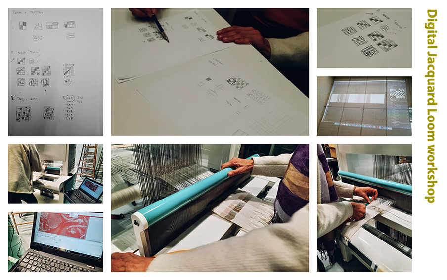
Digital Jacquard loom workshop
We had a digital jacquard loom workshop during week 7 where we got introduced into using photoshop to make the 3 patterns (satin, twill and plain weave) and their variatiors by using grids. Once we stored that patterns we can make more complex patterns based on these variations. The loom is not completely digital, meaning that the manual elements of weaving are still important in the process. The only thing that changes is the making of the pattern digitally.
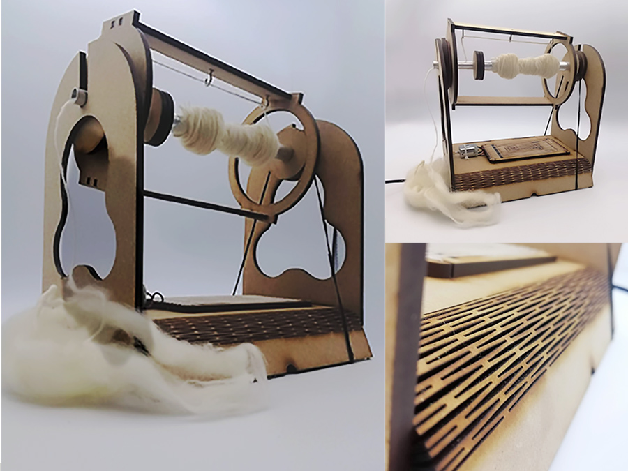
Assembling HILO 2.0 as a team
As a first year node we decided to build studio Hilo’s spinning machine 2.0. We thought that it was a good assignment for the team and that it can help us to develop our own tools.
The day after the lecture we were given the pieces cut. As a team we decided to build the first machine together and see how it works, because we all needed to analyze all the steps and understand how the machine works in order to suggest changes and improvements for our own spinning machine! Building the machine was frustrating for the team in the beggining, as we had several pieces (for more than one machine) and each for a different version. So everything was mixed and we took longer because of this but at the end we ended up having so much fun!
We tested the electronics apart from the structure to understand how the elastic bands work and how much resistance can it make.
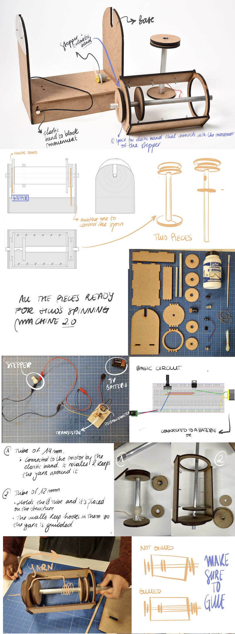
Image by our coursemate Elsa Gil
Working out the electronics and how the machine works
HILO 2.0 electronics circuit
Making spinning machine from HILO from eduardo loreto on Vimeo.
Assembly process of HILO 2.0 as a team
The making of the Ursula spinning multitool
BRAINSTORMING for building a new spinning machine
After getting Hilo’s machine assembled, we decided to do a brainstorming in order to put in common the ideas of our new version of the spinning machine. We divided this brainstorming by dividing our process in 4 fields:
-design of the product
-user experience, electronics
-and other tools or machines that could be linked to our new spinning machine!
We took about 10 minutes of thinking out loud the improvements or features we want our new machine to have!
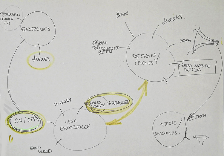
Photo from our brainstorming process
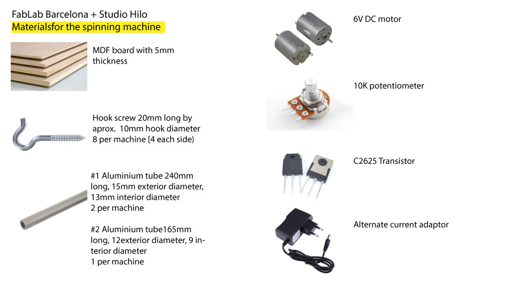
Bill of materials
-5mm MDF board or any other material of your choice

-Check out the picture below to see the rest of the materials analytically!
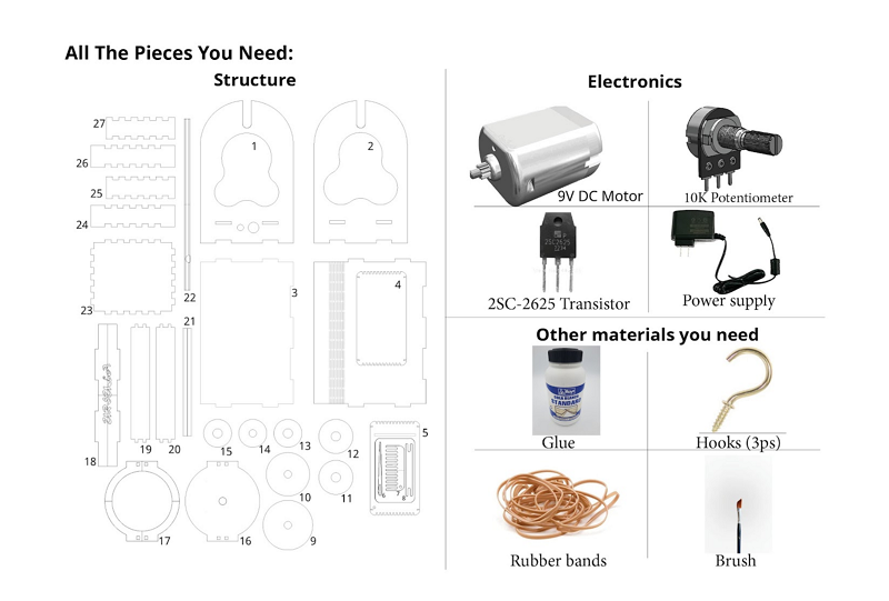
Other tools etc
-Laser Cutter
-Drill
-Glue
-Brush
-Soldering iron
The design- Rhinoceros
After deciding what improvements we would make, it was time to design. We used Catherine Euale’s files to use the same measurements and make sure it would work. From that point, we made changes.
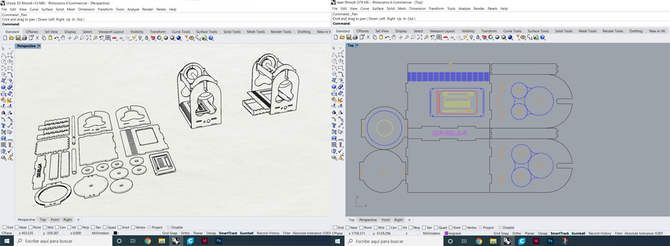
Photo from our coursemate Eduardo Loreto
BASE
We wanted one of the sides to be able to be opened up to see the inside of the machine. We used the Boxes.py website which generates the box that you want and we made a box with a flexible bendy pattern!
It has different shapes and types of box options. The plans it generates are for laser cutting because it has tabs that are used to fit the pieces.
One of the corners had to be “flexible” to open and close the machine. So, once you have entered the parameters, the box is generated with a parametric design to obtain that freedom of movement and you only have to download the file
We made some changes to that file. The box had 2 curved corners, but we wanted one. We combined it with the original file and got the plans of the box we wanted. Moreover, we reduced the height of the base, in order to save material (instead of 6 cm of height, it had 3 cm).
GEAR
We put the gears on the surface of the structure to have more space for other components. They had a circular shape, which complicated their distribution so as not to generate material waste and without affecting the structure of the machine.
As a result, we put 3 of them on each side of the structure and the other one inside the circle that would serve as the lathe structure. There will be waste of material, however we used it as another tool (you will see it).
Moreover, we scaled the diameter of 4 of them, because we noticed that they were just a stopper. The other ones were more “important”, I mean, they were connected to the motor with a rubber band, so if you change the diameter, it will affect the speed. We decided to leave as the original one, just in case.
We maintain the diameter of the holes that are in the gear. We used the same tubes as in the Speed machine 3.0.
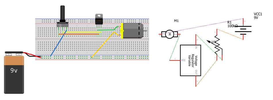
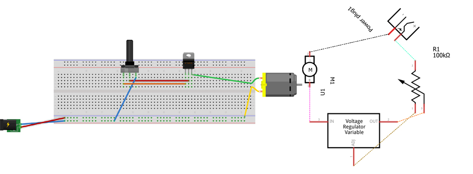
ELECTRONICS
We received a sketch of a circuit with a DC motor connected to a transistor and a potentiometer. This circuit was supplied by a 9-volt battery. We did not have a clear or precise image of what type of transistor or if they have orientation, but like everything with trial and error we could discover it.
After closing the circuit and assembling the machine, we could analize the workflow of the machine. In the updated machine we removed the battery by electrical current using a transformer that we placed at 9 volts. Other changes were to added as an on/off button. However we didn't put it at the final circuit because we didn't see the neccesity. The rest of the circuit stayed the same since it worked perfectly for what we needed.
After approving the changes and everyone being in agree, we got down to work and replaced the elements that we wanted to change in the breadboard, everything worked at the first time so the circuit was ready to passed to the next part of the group that was in charge of making the files in rhino and could integrate the circuit in the design.
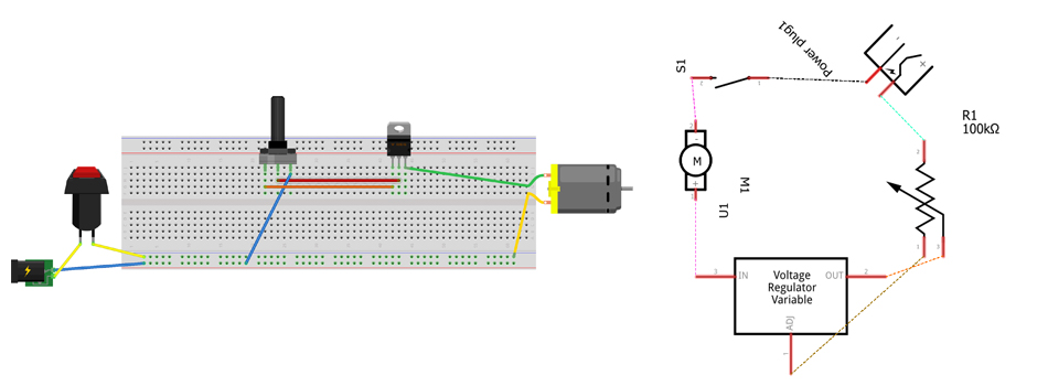
When we place the circuit in the model in rhino we realized that the on and off button was not necessary so we already eliminated the button so we would only be left with the following elements: DC motor, SC2625 transistor, a potentiometer, all this coupled with a DCpower supply.
STRUCTURE OF THE LATHE
We started to place the pieces in order to optimise the space. We saw that the long pieces of the lathe could fit between the pieces of the structure if we reduced their width.
So we reduced it because it didn't affect the operation and it was to our advantage to do so. Instead of having 3 tabs, it would have 2 because they would be too thin and they could break easily.
HOLES
We added some holes to be able to regulate the speed with the potentiometer and another one to pass the power supply cable through.
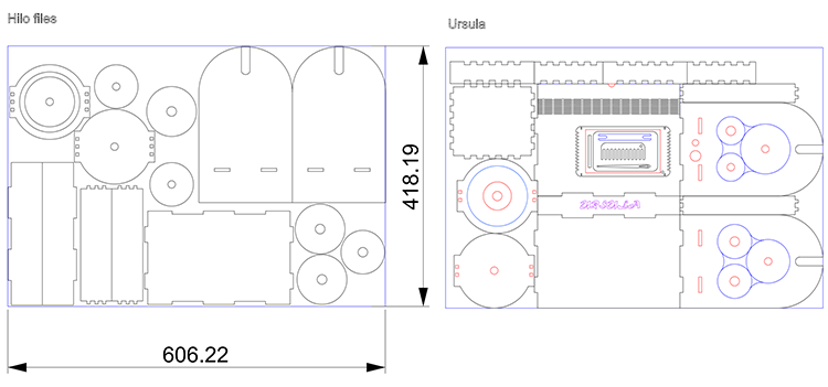
Lasercut process and assemblying the Ursula
You can find he lasercutter parameters on the photos below.
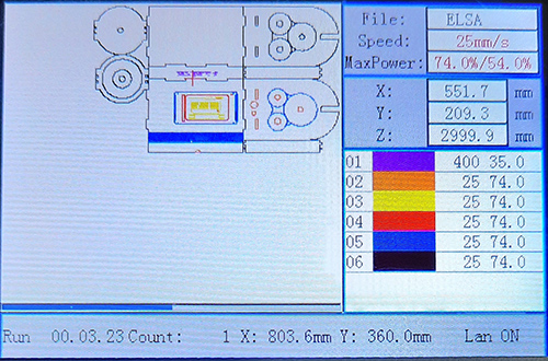
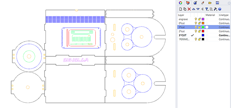
Lasercut settings and order of pieces cut
Here are some images from some 3D renderings of Ursula that we did on Rhinoceros
REDUCING WASTE AND MATERIAL- DISTRIBUTION OF PIECES
This was the distribution of the machine pieces on our 5mm mdf board save material. It is true that we managed to save a little bit, however, we made a 2x1 machine: a spinning machine embedded with a mini loom, plus we added a small box to store other tools.
Lasercutting process ans assembly process for Ursula
Video showing how our machine works
Here you can find all the files for the making of The Ursula 4.0!!!
User manual
My loom designs
project table loom- lasercut loom and tools
I have made this medium sized table loom during my residency at CYENS Thinker Maker Space (1/6/21-1/9/21). It was one of my first projects and the first time I tried using Rhinoceros. After some careful studying of table looms and open source weaving tools I decided to design my own table loom and complementary weaving tools. It is quite portable actually and I have weaved wool and rafia on it already!
totally DIY loom/s
All you need is some scrap or waste mdf board, some nails, or anything else you can imagine and your creativity takes you! Apart from assembling the HILO 2.0 spinning machine and created The Ursula 4.0 we were curious to make some totally DIY and simple looms withour any fancy technologies and digital fabrication techniques.
From the waste material from HILO 2.0 we made 2 small circular looms by simply measuring and hammering some nails on the diameter of our circle and by hand sawing the edges to make small incisions around the diameter of the circle.
Circular loom 1
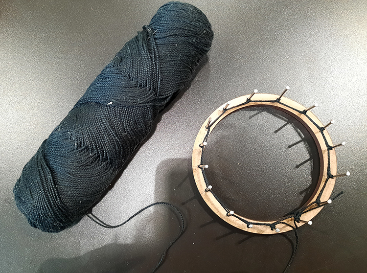
Circular loom 2
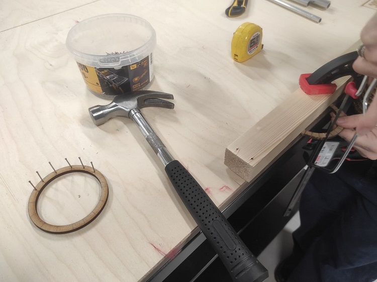
For the 2nd small circular loom I used a hand saw to make small insicions around the diameter of the circle! This allowed me to warp my loom this way and have some fun!
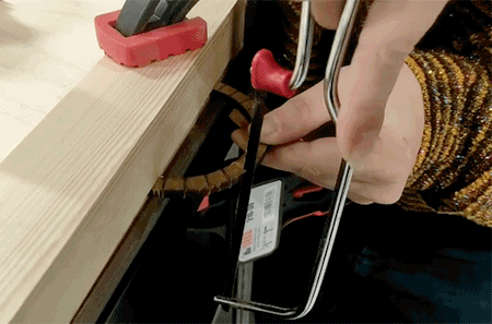
Demonstrating how I use the hand saw to make the loom
Circular loom designed on Rhinoceros

*Workflow process on Rhinoceros
Rectangular loom designed on Rhinoceros
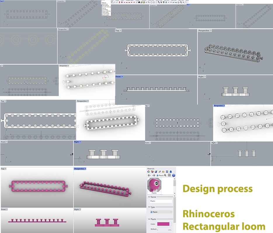
Workflow documentation on Rhinoceros
Useful links
- Catherine Euale
- Markdown
- STUDIO HILO
- Circular Knitic github
- Lara Campos fabricademy 2019, Open Source Hardware, from fibres to fabric week
- Boxes.py
- Preparing your fibres for spinning