10 Open Source Hardware - From Fibers to Fabric
Research and Ideation
Last month I bought a Sizzix press machine online to die cut my handmade paper. It took several weeks to get here and I had to pay double the price. I saw it had a relatively simple mechanism and thought why not make one in Jordan? Therefore, I suggested we make a printing press machine this week. And we all agreed.
We started with a market and precedents research and divided the research into two parts: machine design and printmaking materials. For the design, we had to think about two main points: how the print "sandwich" will move through the machine and how the machine could acommodate different material thicknesses. We found two main mechanisms:
- Roller moves on plate
- Plate moves between two rollers
We started comparing the machines we found and categorizing the mechanisms in this Miro board.
Printmaking Experiments
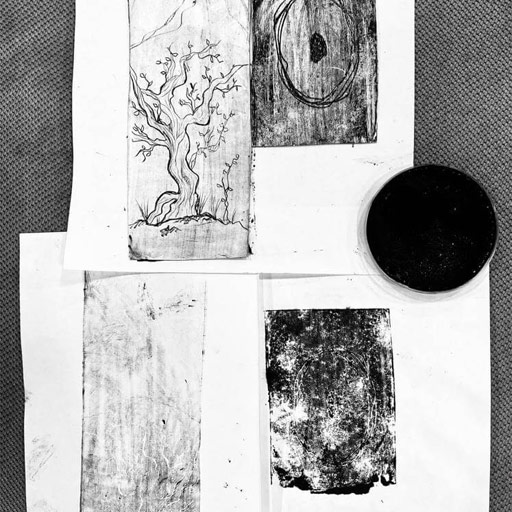
We were planning to have a kit with bio-based inks and recipes with the machine. That didn't happen as it needed more time for experiments and developing the best ink recipes. But we had a lot of fun experimenting with alternative printmaking techniwues and bio-based inks. I tried to make ink using Gum Arabic as a binder and charcoal as a dye.
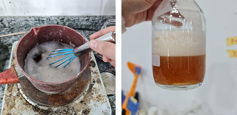
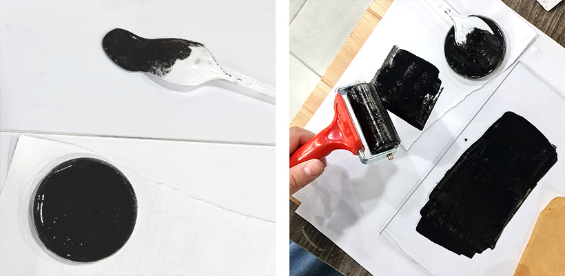
Gum Arabic binder recipe
add crushed gum arabic (acacia tree resin) to lukewarm water (1:2). Keep stirring and don't let it boil. When it becomes thick and honeylike take it off. Mix your chosen dye with the binder.
I tried different materials for stamps with this ink. It wasn't working very well but there is hope.
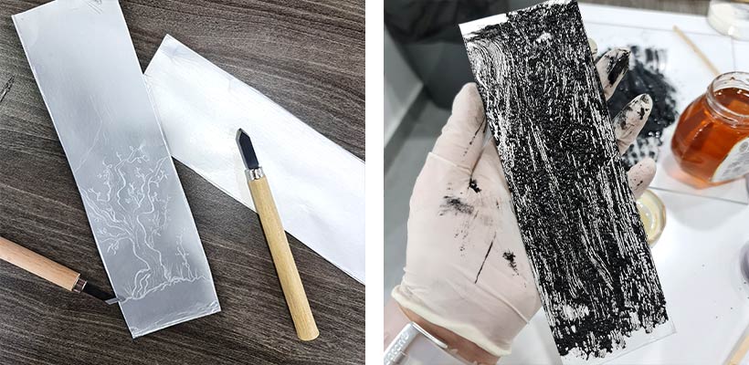
I also tried carving images on the inside of tetra paks which was something I've been meaning to try since a while now. One printmaking technique is called etching, where an image is carved on a metal sheet. Ink is applied on the surface then wiped clean but the carvings still hold the ink. And then it is put in a press machine with damp paper to catch the ink. It gives incredible detail. I read it can be done using tetra paks. It wasn't a very successful trial but it was inspiring to make. I used honey as a binder here.
Prototyping
Rapid Prototypes
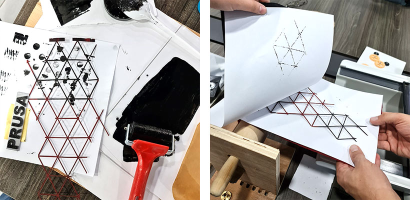
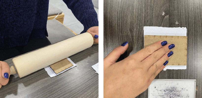
We Started testing the concept by making some prints by hand and by a kitchen roller.
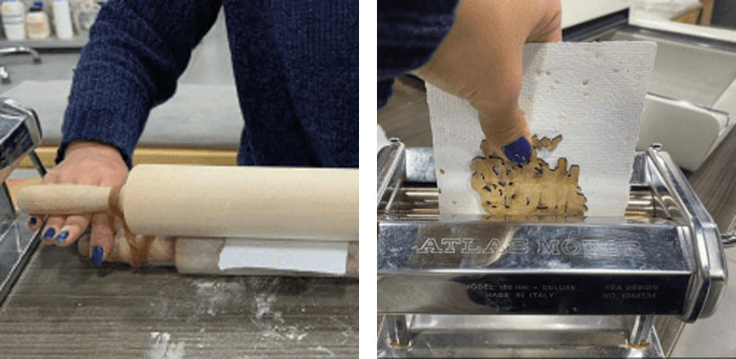
Then we made this low-fidelity prototype which didn't work very well because not enough pressure was applied by it. I also brought my mom's pasta machine to try it, too.
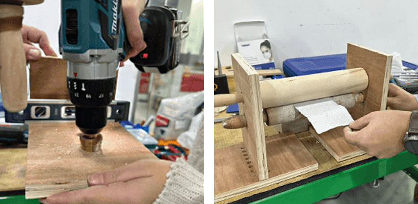
After that, we mounted two kitchen rollers between two pieces of wood to test if we can actually move the plate between two rollers. It worked.
Now that we tested the printing and movement method, we went to design the machine and think about the second aspect: adjusting the machine for different thicknesses.
First Prototype
Shahd is really talented when it comes to 3D modelling and computational design. She made these cool digital model iterations and started thinking about the aesthetics of the machine. We decided on a minimal design.
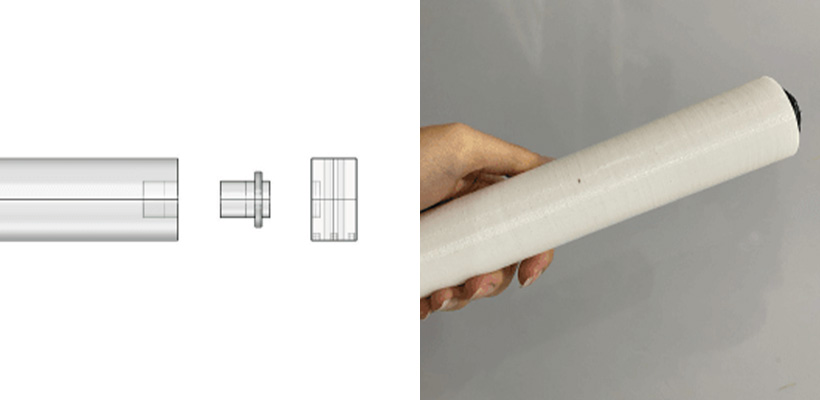
We decided to try printing the roller to be able to control its width and length and the connections.
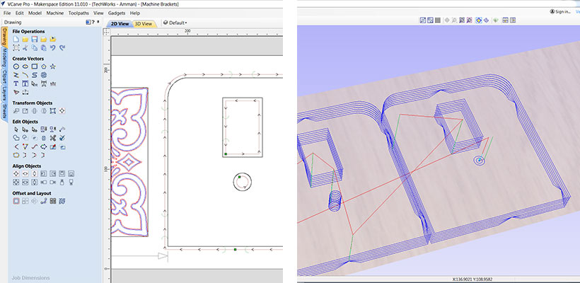
And we cut the sides from 22mm plywood using a CNC milling machine after preparing the file using Vcarve software.
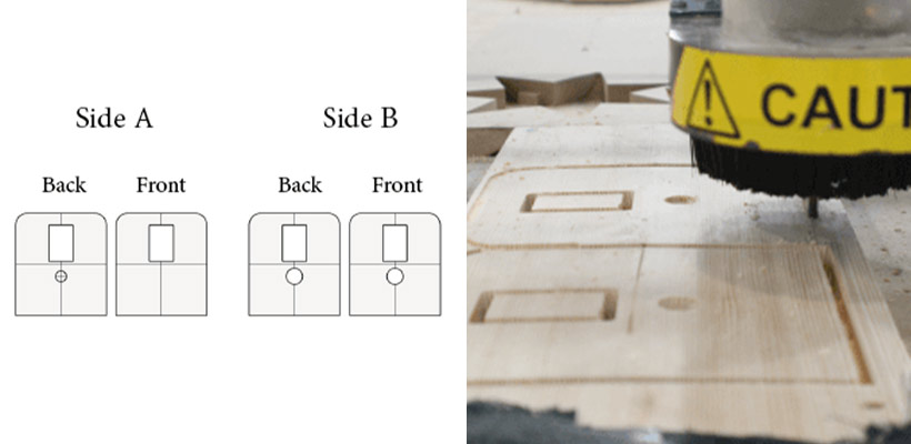
CNC mill settings
The CNC we have at the lab is a Shopbot.
To cut the 22mm plywood we used an endmill 1/4" (0.25 inch diameter) with 2 flutes
Tool Settings
Cutting Parameters: Pass Depth = 0.21 inch | Stepover =0.1 inch 40%
Feed and Speeds: Apindle Speed = 14000 rpm | Feed Rate = 1.8 inches/sec | Plunge Rate = 0.9 inches/sec | Chip Load 0.0039 inches
Toolpath Settings
Cuttind Depth = 24.5 mm
Passes = 7
Tool travels outside the path with Allowance Offset = 0.0 mm
Tab Options: Langth = 20 mm | Thickness = 10 mm | 3D tab
The most tricky part in the machine was this piece that should connect the rollers and allow them to move vertically to take different thicknesses of "sandwiches". (A sandwich is the group of layers we put between the ayers to make a print or a cut). This piece was not working at all in this prototype so we had to redesign it.
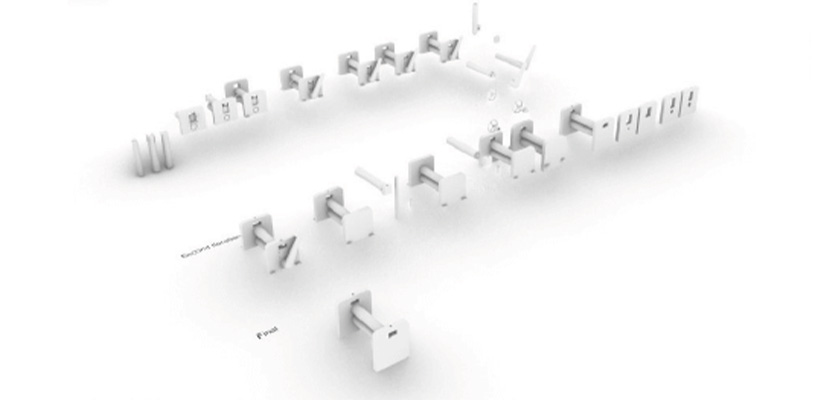
A cool visualization of our first prototype done by Shahd.
And our first prototype.
Rethinking the Mechanism
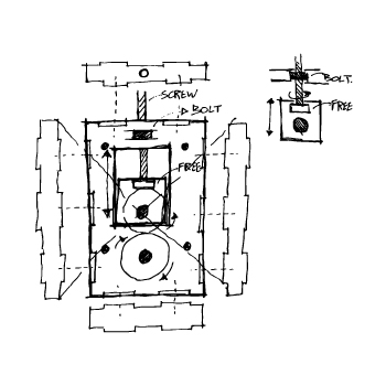
Since the tricky piece that was supposed to hold the rollers and allow them to move vertically was not working well, we had to rethink it. I made these sketches on the wall in the meeting room. I felt like those mad scientists we see in the movies!
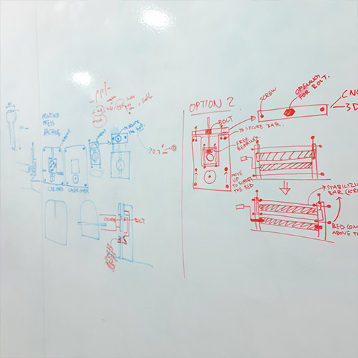
For the holder piece to be able to move vertically and stay at its position, I had to think about the parts that should be able to rotate freely and the parts that should be fixed. I bought some screws and different types of bolts and tried different iterations to understand the movement. Then, I made a rapid prototype using a laser cutter, a screw, a bolt, and some tape. I did a few more prototypes as seen in the right photo.
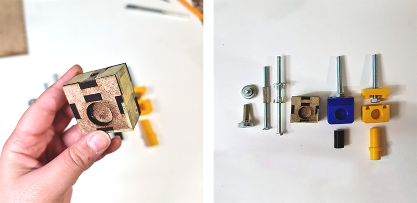
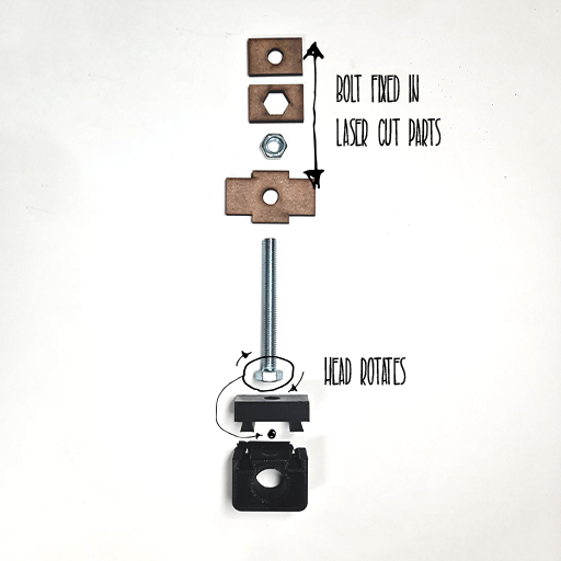
When I found everything working good, I made a -hopefully final- 3D printed prototype. We tested it in the machine. And it works!
Awesome. let's have a little look on how we made the body of the machine and put everything together.
I started by taking the measurements from the first prototype and drawing some rectangles for the sides and roller holders on Rhino. Then I measured the roller's diameter and decided on their places. I wanted them to touch each other when the top roller is at its lowest point. Just in case we needed to print something extra thin. I took the measurements of the screw and bolt I bought to fit them properly in the design. You can see the screw and bolt drawn here as well.
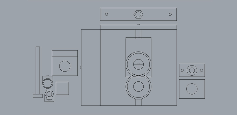
At some point, I decided to cut the pieces using the CNC milling machine so I made this quick model.
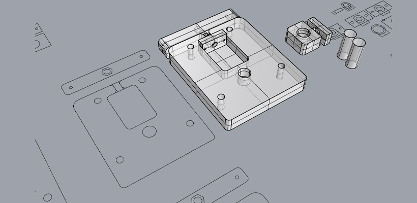
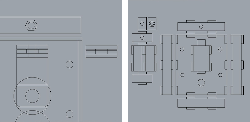
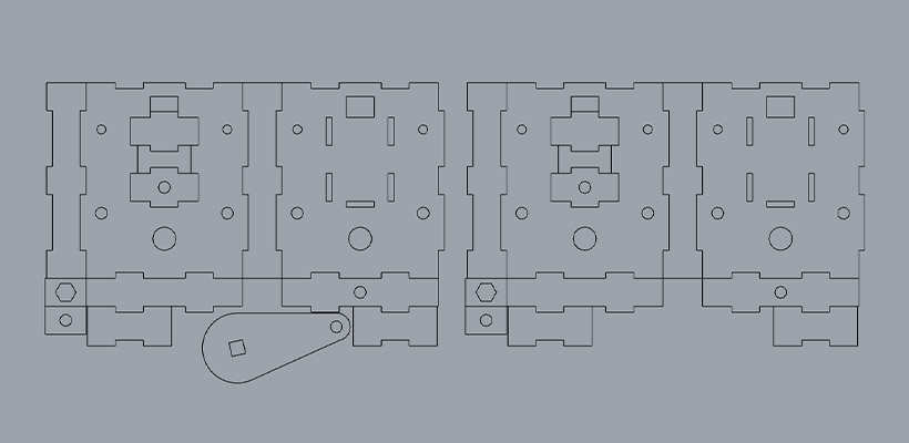
I then changed my mind. A CNC machine isn't available in every makerspace. It is much more expensive and difficult to operate. Making the pieces with a laser cutter seemed a more logical and user-friendly option. So I turned the design into these rectangles. On the image at the left I made an offset from the main rectangle to account for the material thickness to draw the fingers. You can also see little rectangles on the side. I made three layers of wood to hold the bolt in its place: the middle layer has a cut the shape of the bolt and the other two have circular openings the diameter of the screw. I drew these rectangles to calculate the height of the layers and where to put the openings to fit them into the main body.
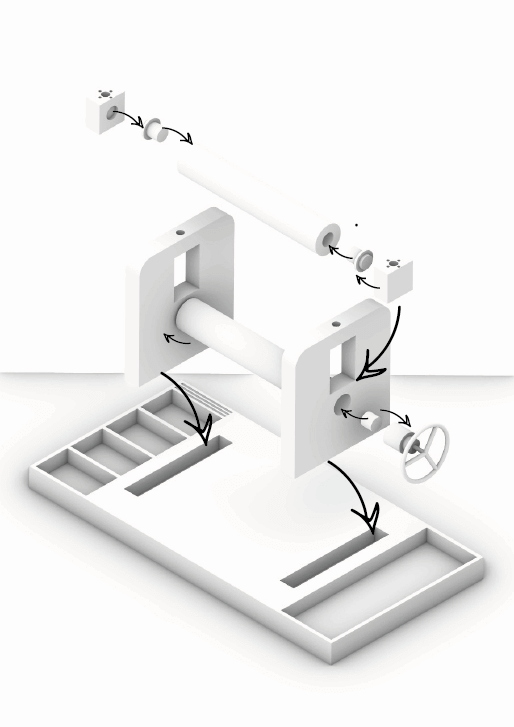
Printing Press Machine
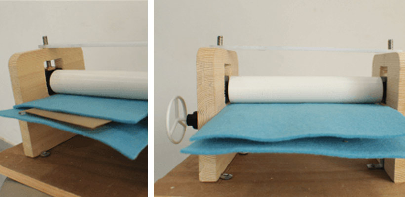
And here it is! Our affordable, easy to fabricate and assemble printing press machine.
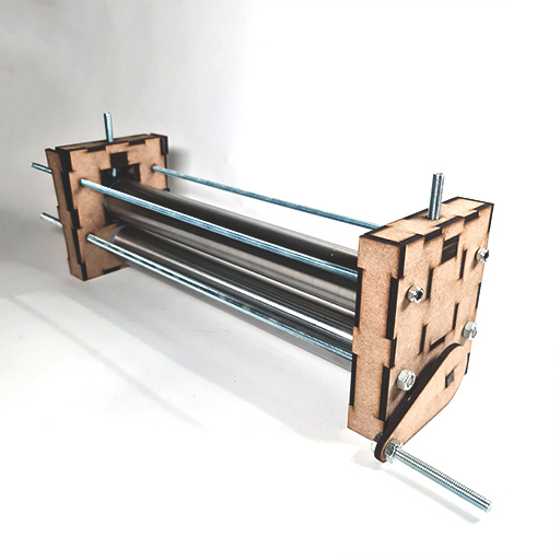
We tried to fit the pieces of the design on the board to reduce waste material as much as possible.
Laser cut settings
we used mdf 4.7 mm as a material.
These are the laser settings for the Trotec speedy 400
Power: 100
Speed: 0.5
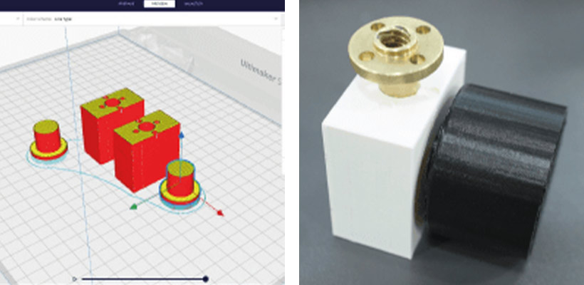
We exported the roller holder 3D model as .stl to Cura to print it. We printed it on Ultimaker S5 with 0.2 layer height. The cylinders go into the rollers. The one with the cube is to attach the arm to rotate the rollers.
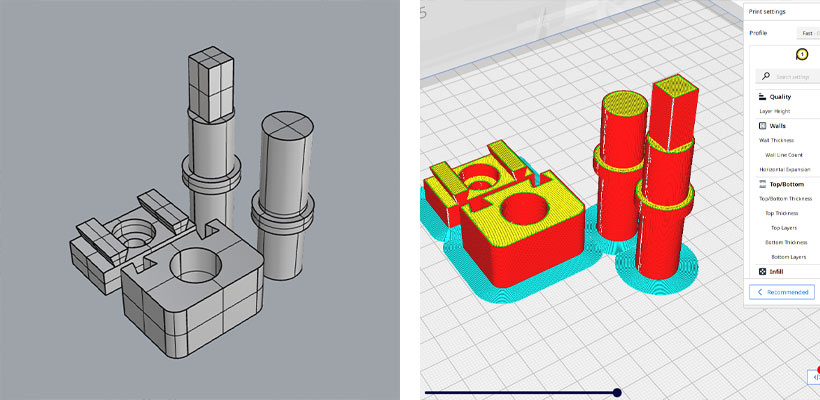
3D printing settings
Printer: Ultimaker S5
Layer height: 0.2 mm
Wall thickness: 0.8 mm
Top/bottom thickness: 0.8 mm
Infill: 15% triangles
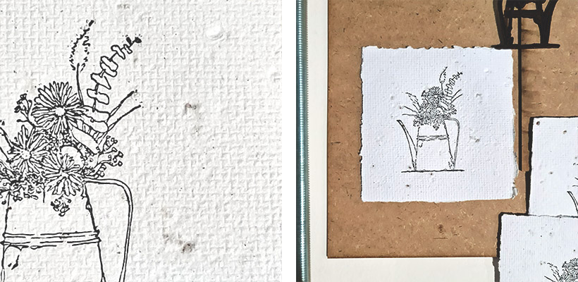
I tried making a print using a stamp I already had. The stamp is made using laser engraving on 3mm mdf wood. The results were surprisingly amazing! Look at the details!
Bill of Materials
| Qty | Description | Price | Notes |
|---|---|---|---|
| 1 | mdf board 5mm | 6.00 $ | 60*22 cm is needed |
| 2 | dough roller | 6.00 $ | as wide as the size you want |
| 2 | screw D8mm 10cm | 0.25 $ | |
| 4 | screw bar 8mm | 1.00 $ | |
| 18 | bolt 8mm | 0.1 $ | |
| - | PLA filament | - |