5. E-textiles

So this was a week when I thought my Fab Academy training might help make my journey a bit easier. The electronics aspect of this week's work should not be so daunting, but I have never integrated electronics into a wearable before. As with every Fabricademy assignment, I don't want to rush to just complete the assignment, but instead do what most of my student colleagues are doing...and think hard about why and how I do something.
Assignment
So this week we are to explore the concept of Soft Electronics or making electronic circuits using conductive and resistive textiles. To complete the assignment, we are to...
- Make a Digital Soft Sensor swatch
- Make an Analog Soft Sensor swatch
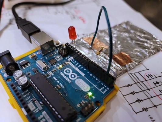
- Connect the Analog Soft Sensor to an Arduino and observe the Analog readings using AnalogRead

- Combine 2 Soft Sensors to make an integrated e-Textile piece
Assignment Work
Research
Soft Sensor
I know that a 'sensor' is an electronic INPUT device that gathers data from the environment to be processed by a microcontroller. But what is a Soft Sensor? In the context of Fabricademy, I believe that a Soft Sensor...is an electronic INPUT device that utilizes conductive and resistive textiles...with a sense of softness...in its fabrication and implicitly minimizes 'hard' electronics components as much as possible.
Digital vs Analog
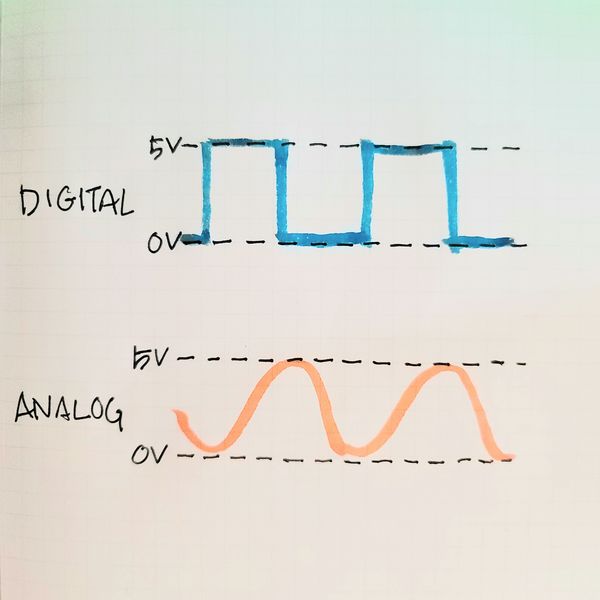
A Digital signal is a Binary state signal...it is either ON or OFF...0V or 5V. It generates a Square Wave signal profile.
An Analog signal can smoothly or gradually transition from the minimum state to the maximum state...can be any voltage level between 0V and 5V...such as 2.47V. It generates a smooth Sine Wave signal profile.
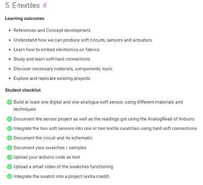
Digital Swatch
The Digital Swatch is a simple circuit with a paperclip is used as a switch...to OPEN/CLOSE the circuit...turn the LED ON or OFF (binary state). The components of the circuit include...
- LED
- Brass Wire
- Paper Clips
- 3V Battery
- Conductive Thread
- Felt
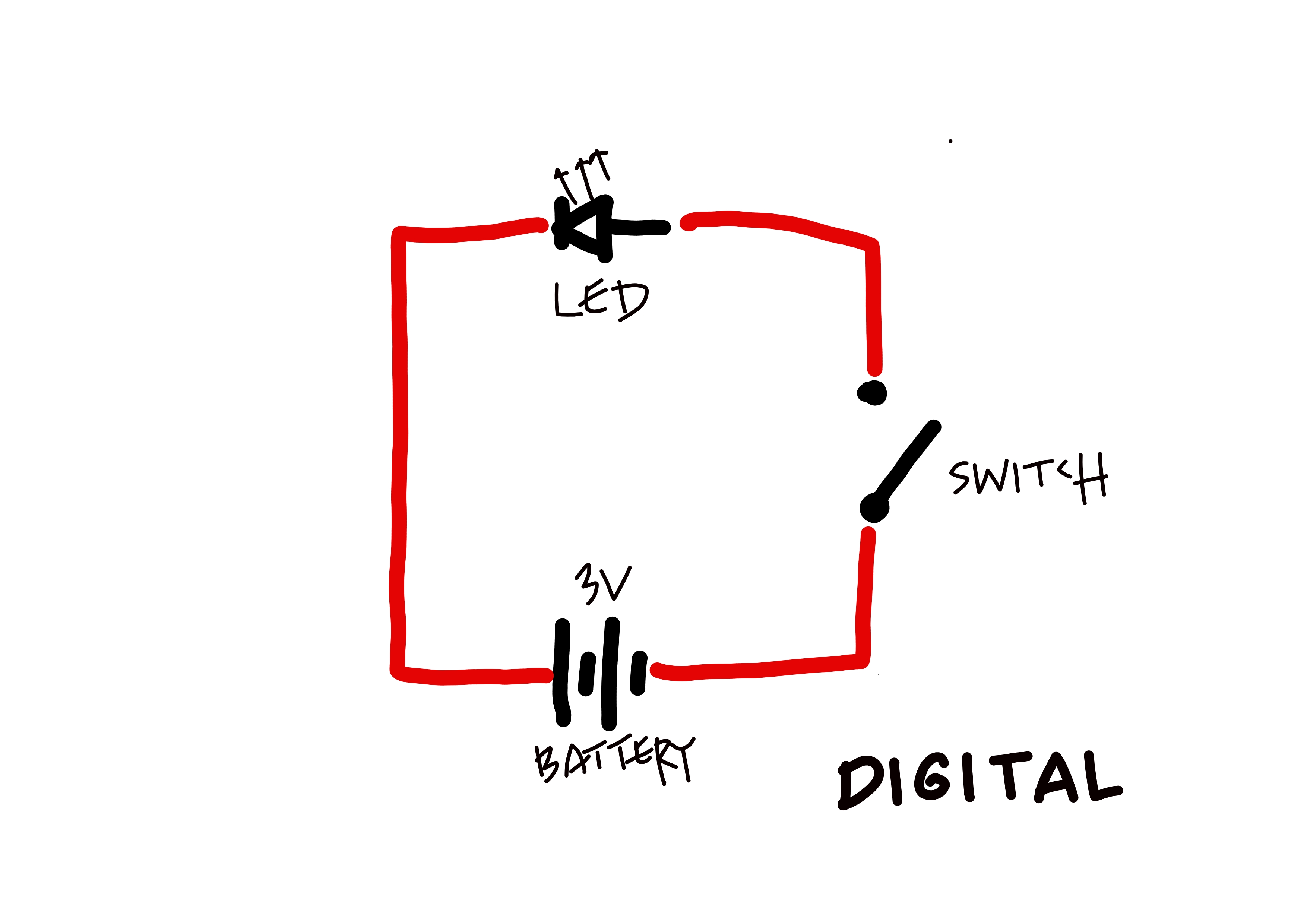
Two paperclips are used as the battery holder, one to make contact with the negative side of the battery and the other the positive side. On the negative side, conductive thread is sewn from the negative paperclip to the negative leg of the LED. On the positive side, conductive thread is sewn from the positive paperclip up to another paperclip...the switch...that can rotate around its one fixed end. From the positive leg of the LED, a bent brass wire is connected...to serve as the fixed contact for the paperclip switch.
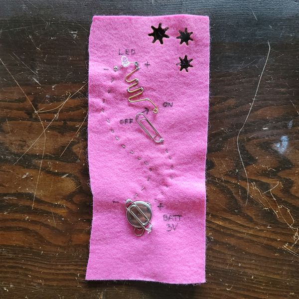
Analog Swatch
The Analog Switch utilizes a Light Dependent Resistor (LDR) as the Analog Sensor. The LDR's resistance increases (allowing less electrical current to pass through) as less light shines on it...and less resistance (more electrical current passing through) when bright light shines on it. The LED's brightness fades (not switches) from bright to dim as shadow is cast upon the LDR. The components of the circuit includes...
- LED
- Light Dependent Resistor
- Paper Clips
- 3V Battery
- Conductive Thread
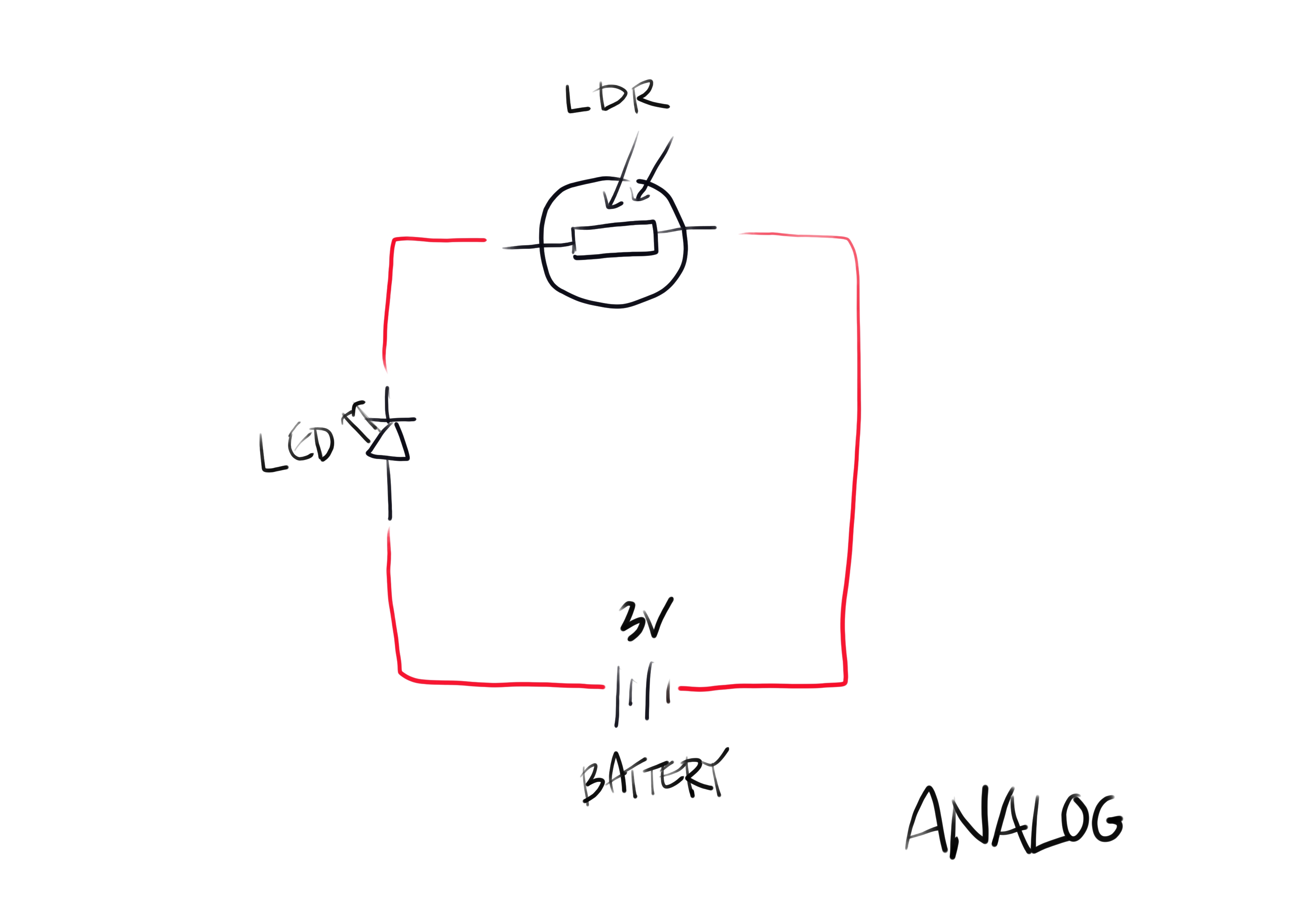
Like on the Digital Switch, 2 paper clips are used to hold the battery. Conductive thread is sewn from the positive paperclip to the positive leg of the LED. Similarly, conductive thread is sewn from the negative battery paperclip to the negative leg of the LED...passing through the LDR on the way.
Project Research & References
Project 1: LED Shadow Sensor
I had read somewhere in the past, that an LED can be used as a light sensor...similar to an LDR...by reversing the LED's connection to positive and negative power lines.
I watched this video by Sparkfun to learn how to use LEDs as Light Sensor. . I learned that when a reverse voltage is applied across the LED's pins...electricity will charge the small capacitor made up of the PN-junction in the LED.
In the video LED as Light Detector (and Switch), further explanation was provided by Ludic Science. In particular, I learned that amplifying the small current generated when an LED (forward biased) is exposed to strong light can be done with transistors.
Makezine also provided useful instruction on how to use an LED as Light Sensor.
Geek Note: PN-Junction, Forward Bias & Negative Bias
- The semiconductor material on the N-side of the junction has excess electrons while the P-side has a deficiency of electrons ("holes")
- When the P-side has a higher electrical potential than the N-side...a 'Forward Bias' state occurs and electrons from the N-sde flows to the P-side, while "holes" flows from the P-side to N-side...towards the electrons.
- If the "holes" and electrons meet...energy is emitted in the form of light (gallium arsenide phosphide semiconductor and dope).
- If the N-side is given higher electrical potential than the P-side...a Reverse Bias state occurs
- The holes and electrons are pulled away from each other...enlarging the 'depletion region' (no man's land) between the N and P materials
- If a photon hits the 'depletion region'...it may give up its energy to an atom, freeing an electron and allowing it to roam freely...generating a hole at its origin point
- The hole is attracted to the N-side and electron to the P-side...and this 'motion' generates an electrical current...and the Light Sensing functionality.
- The N-side pin (the negative leg)...can be used to generate input signals to a microcontroller unit (MCU)
- Timing how long it takes for the diode to discharge...more light falling on the LED = faster discharge
Instruction on building a simple circuit for the light sensor is also provided by Sparkfun.
Other notes for using an LED as a Light Sensor...
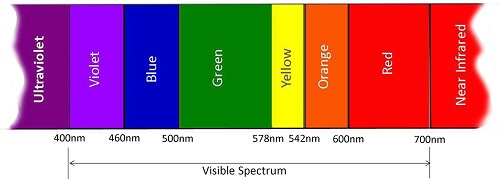
- "LEDs will be sensitive to light which has the wavelength equal to or lesser than it"
- RED is the ideal color...as it has the longest wavelength at 620nm - 750nm (450nm -495nm for Blue, the shortest wavelength visible color)
- When light hits a PN-junction when the LED is in a Reversed Bias configuration...a tiny current is produced
- The P-side and N-side are like plates holding a charge with an insulator (the depletion region) separating them...similar to a Capacitor
- Applying a reverse voltage to an LED makes it act like a capacitor
- When light falls on the reverse bias LED...a current is created and discharges the 'capacitor'
- More light = faster discharge
- Tip: The INPUT LEDs ned to be as close to the MCU's pins as possbile...avoid inductance and capacitance issues from wires and breadboards
LED Light Detector Breadboarding
Instructables: LED as light sensor
Step 1: LED as Light Sensor
BOM:
- Arduino Uno
- 1x LED
Procedure:
- Connect 'Sensor' LED to Arduino Uno...
- -ve leg to GND
- +ve leg to Analog Pin 0
- Use Arduino IDE's Serial Monitor to display Analog signal levels generated by LED Light Sensor

// LED as Analog Light Sensor
// by Rico Kanthatham, Fabricademy 2023

int sensorIn = A0; // Light Sensor pin
int sensorReading = 0;
int sensorLevel = 0;

void setup() {
  Serial.begin(9600); // Initiate Serial Communication

  pinMode(sensorIn, INPUT); // Specify Light Sensor pin as in INPUT pin
}

void loop() {
  sensorReading = analogRead(sensorIn); // Read analog signals from the sensor pin...assign to variable 'sensorReading'
  sensorLevel = map(sensorReading,0,1023,0,3000); // Remap 'sensorReading' values to bigger ranged 'sensorLevel' values

  Serial.println(sensorLevel); // Display 'sensorLevel' values in the Serial Monitor
}
- Success! - Displayed values in Serial Monitor for ambient light conditions...avg 240

- Displayed values in Serial Monitor for bright light conditions...> 280

Step 2: Light Sensor as ON/OFF Switch
- Connect Blue LED...-ve leg to GND, +ve leg to pin 13 of the Arduino Uno
- Use Light Sensor Ambient vs Bright values to trigger Blue LED ON/OFF
// LED as Analog Light Sensor
// by Rico Kanthatham, Fabricademy 2023
// White LED as Light Sensor
// Blue LED turns ON when shadow detected

const int sensorIn = A0;
const int LEDpin = 13;

int sensorReading = 0;
int sensorLevel = 0;

void setup() {
  Serial.begin(9600);

  pinMode(sensorIn, INPUT);
  pinMode(LEDpin, OUTPUT);
}

void loop() {
  sensorReading = analogRead(sensorIn);
  sensorLevel = map(sensorReading,0,1023,0,3000);
  Serial.println(sensorLevel);

  if (sensorLevel < 280) {
    digitalWrite(LEDpin, HIGH);
  } else {
    digitalWrite(LEDpin, LOW);
  }
}
Project 2: Capacitive Touch Sensor > AnalogRead
I experimented with using a Capacitive Touch Sensor with the Arduino microcontroller...to view values produced by the AnalogRead command.
Experiment 1: Arduino + Capacitive Touch Sensor
Instructables: Arduino + Capsense library
Utilize the Capacitive Sensor library by Paul Bagder and Paul Stoffregen to make an Arduino Uno + Capacitive Sensor super easy.
Install the library in Arduino IDE by using 'Tools > Manage Libraries...' then typing 'Capacitive Sensor' in the search window and click 'install' when the library appears in the library list window below.
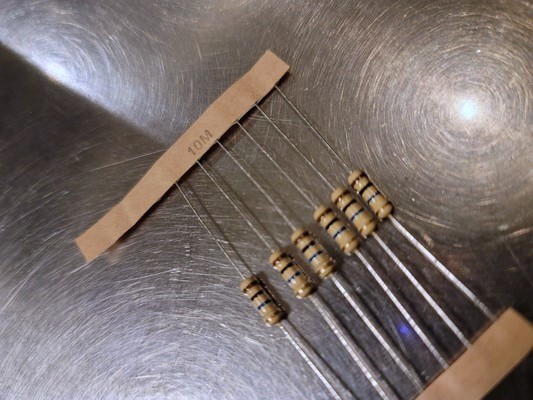
BOM: - 1x Arduino Uno (MCU) - 1x 10M ohm resistor - 1x Conductive Touchpad
- The Arduino measures how long it takes for the Touch Sensor (capacitor) to charge...estimating its capacitance
- Capsense Library...requires one 'Send Pin' (10M ohm resistor) and any number of 'Receive Pins'...the 'Send Pin' is connected to the 'Receive Pin' via a medium to high value resistor
- Use a 1M ohm resistor and touch required to activate
- Use a 10M ohm resistor...sensor reponds from 4-6 inches away
- Use a 40M ohm resistor...the sensor responds from 12-24 inches away (depending on foil size)
- But larger capacitor = slower response
- The 'Send Pin' sends a (digital) square wave (40Hz) thru a 1M resistor to the 'Recieve Pin'
- The length of time required for the signal to be received (for the Receive Pin to go from LOW state to HIGH state)...can be used to estimate the capacitance
- The CapSense Library keeps track of time in terms of 'Program Ticks'
- If a conductive touchpad is connected to the 'Receive Pin'...touching the pin, increases the capacitance of the circuit...elongating the time for 'Receive Pin' to go HIGH
- The deviation between the 'No Touch' and 'Touch'...'Time to Receive'...is interpreted by the MCU as a touch action
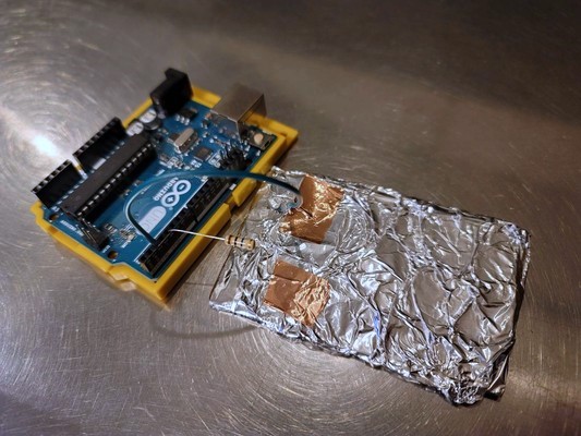
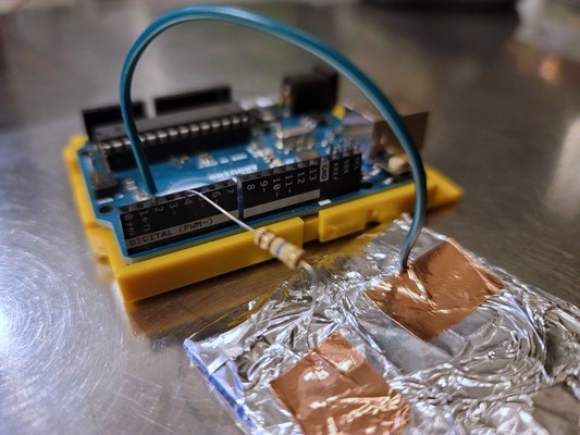
Circuit Building:
Aluminum Foil + Wire + Copper Tape + 10M ohm resistor = (cheap and cheerful) Capacitive Touchpad
- Attach the 1M ohm resistor to the conductive touchpad with copper tape
-
Attach a length of wire to the conductive touchpad with copper tape
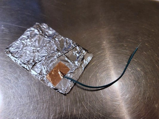
-
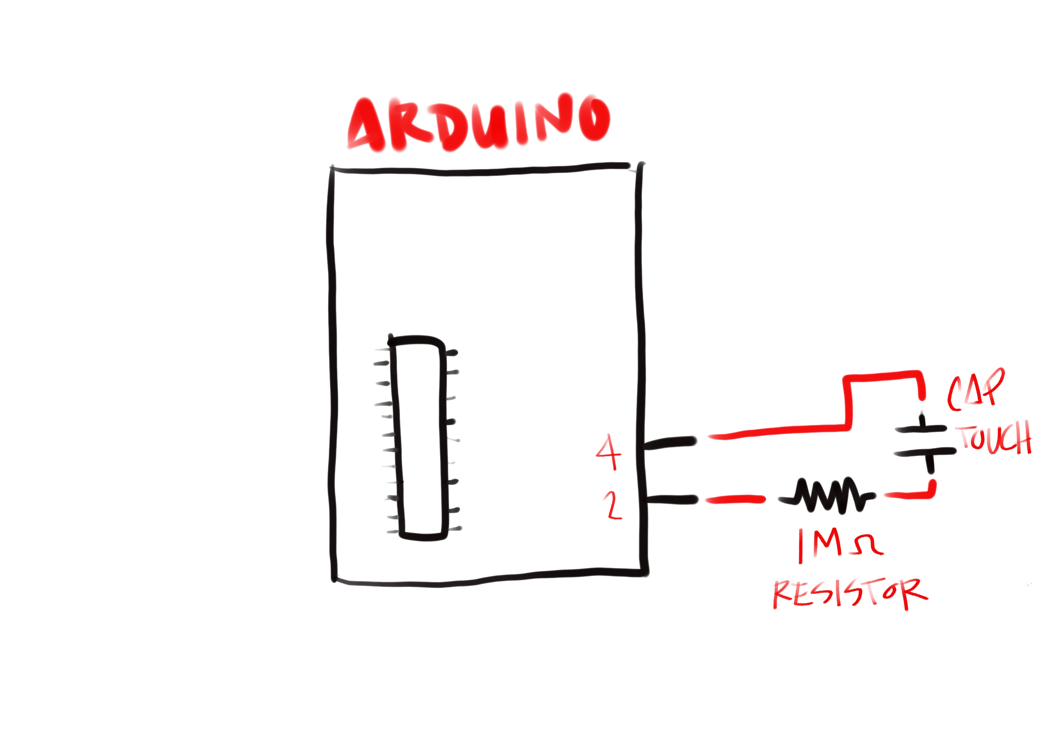
Connect the free leg of the resistor to digital pin 4 of the Arduino Uno
- Connect the free end of the wire to digital pin 2 of the Arduino Uno
Programming
/*
 * CapitiveSense Library
 * Paul Bagder 2008
 * Uses a high value resistor e.g. 10M between send pin and receive pin
 * Resistor effects sensitivity, experiment with values, 50K - 50M. Larger resistor values yield larger sensor values.
 * Receive pin is the sensor pin - try different amounts of foil/metal on this pin
 */
// Refactored by Rico Kanthatham, Fabricademy 2023
// Testing one touchpad...kitchen foil...with 10M ohm resistor

#include <CapacitiveSensor.h> //Include the Capacitive Sensor library

CapacitiveSensor   CapSense1 = CapacitiveSensor(4,2); // Create a Capacity Sensor object called 'CapSense1'...Pin 4 as Send Pin, Pin 2 as Receive Pin

void setup(){
   Serial.begin(9600); // Initiate Serial Communication
   CapSense1.set_CS_AutocaL_Millis(0xFFFFFFFF);     // Initialize/Calibrate the Capacity Sensor Object
}

void loop(){
    long transmitTime =  CapSense1.capacitiveSensor(30); // Elapsed time in Program Ticks

    Serial.println(transmitTime);                  // print sensor output 1
    delay(10);                             // 10 millisecond default delay between value send
}
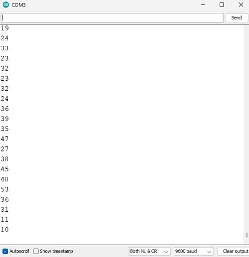
Testing:
Serial Monitor Output > No Touch
- Values range between 20 and 60
- Value scroll speed is fast...in the Serial Monitor...maybe 20-30 values per second?
Serial Monitor Output > Hand Hover ~5cm Above Touchpad
- Values range between 200 and 230
- No noticeable slow down in values scrolling
Serial Monitor Output > Touch
- Values greater than 200k
- Value scroll speed slows to 1 per second
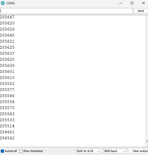
Success!!
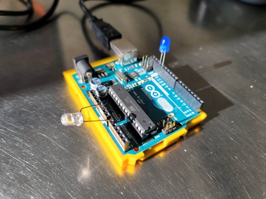
Experiment 2: Arduino + Touch Sensor (Switch) + LED
Now...make this capacitive touchpad into a switch...to turn an LED ON/OFF
- Connect an LED with its +ve leg to Pin 13 and -ve leg to GND
/*
 * CapitiveSense Library
 * Paul Badger 2008
 * Uses a high value resistor e.g. 10M between send pin and receive pin
 * Resistor effects sensitivity, experiment with values, 50K - 50M. Larger resistor values yield larger sensor values.
 * Receive pin is the sensor pin - try different amounts of foil/metal on this pin
 */
// Refactored by Rico Kanthatham, Fabricademy 2023
// Testing one touchpad...kitchen foil...with 10M ohm resistor

#include <CapacitiveSensor.h> //Include the Capacitive Sensor library

int LEDpin = 13;

CapacitiveSensor   CapSense1 = CapacitiveSensor(4,2); // Create a Capacity Sensor object called 'CapSense1'...Pin 4 as Send Pin, Pin 2 as Receive Pin

void setup(){
   Serial.begin(9600); // Initiate Serial Communication

   pinMode(LEDpin,OUTPUT);
   CapSense1.set_CS_AutocaL_Millis(0xFFFFFFFF);     // Initialize/Calibrate the Capacity Sensor Object
}

void loop(){
    long transmitTime =  CapSense1.capacitiveSensor(30); // Elapsed time in Program Ticks

    Serial.println(transmitTime);                  // print sensor output 1
    delay(10);                             // 10 millisecond default delay between value send

    if (transmitTime > 200000){
      digitalWrite(LEDpin,HIGH);
    } else if (transmitTime < 20000){
      digitalWrite(LEDpin,LOW);
    }
}
Success!!!
- When the touchpad is touched...the LED turns ON
- When the finger is lifted from the touchpad...the LED turns OFF
- I note that there is a 1 second delay to turn ON the LED, but turning OFF the LED is instantaneous
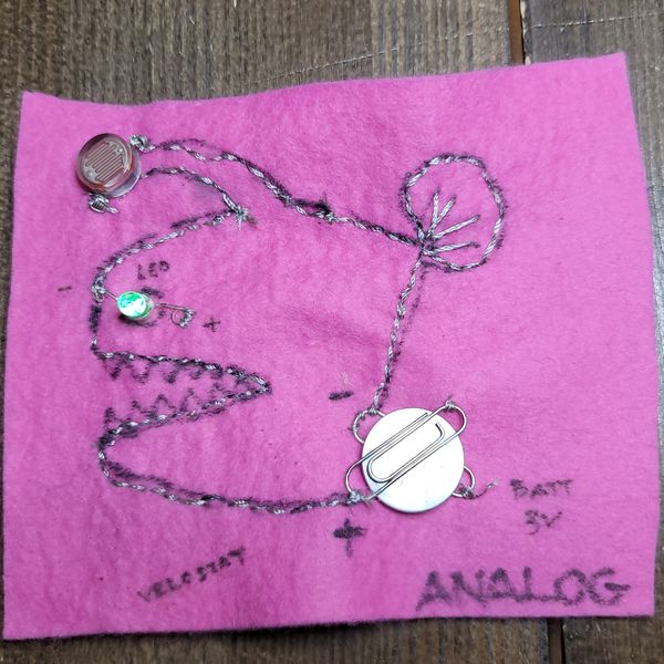
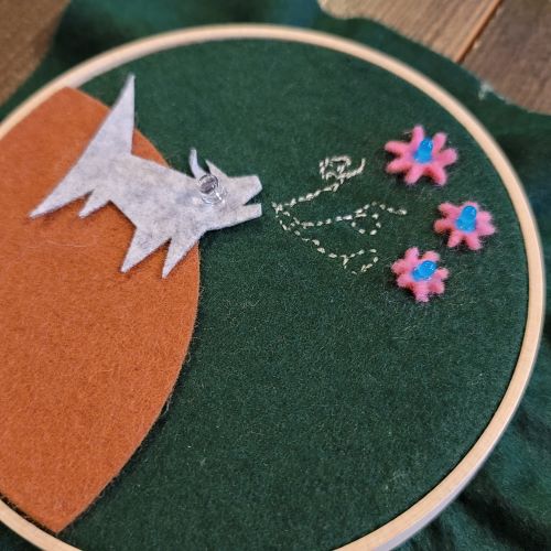
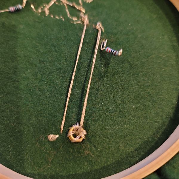
Integration Project > Howling at the Stars
My integration project...
- Uses an LED in a Reversed-Bias configuration as a Light Sensor...connected to an Analog pin and GND pin of the Arduino Uno
- On the soft-electronics textile construction are 4 LEDs...one RED and 3 BLUE...connected to common GND and 4 different digital pins on the Arduino Uno
- When the Light Sensor is brightly lit...the wolf's RED LED eye is ON
- When the Light Sensor is dimly lit...the BLUE LEDs of the stars blinks in a random pattern
// LED as Analog Light Sensor
// by Rico Kanthatham, Fabricademy 2023
// White LED as Light Sensor
// Blue LED turns ON when shadow detected

const int sensorIn = A0;
const int LEDpin = 11;

int brightness = 0;
int fadeRate = 5;

int sensorReading = 0;
int sensorLevel = 0;

void setup() {
  Serial.begin(9600);

  pinMode(sensorIn, INPUT);
  pinMode(LEDpin, OUTPUT);
}

void loop() {
  sensorReading = analogRead(sensorIn);
  sensorLevel = map(sensorReading,0,105,0,300);
  Serial.println(sensorLevel);

  if (sensorLevel > 600) {
    fadeIn();
  } else {
    digitalWrite(LEDpin, LOW);
  }

  delay(100);
}

void fadeIn() {
  if (brightness <= 0 || brightness >= 255){
    brightness = brightness + fadeRate;
    analogWrite(LEDpin, brightness);
    delay(30);
  }
}
The project works reasonably well...but the Reverse-Bias LED is not a perfect Light Sensor and readings are not stable. Using a proper light sensor would make for a better result.
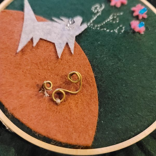
I realized that the assessment guidelines requires the combination of 2 soft sensors...so I added a switch to my construction...2 bent wires connected to the circuit via conductive thread. The circuit closes and allows the LED ON/OFF functions described above...when the rotating switch lever is rotated counter-clockwise to make contact with the fixed brass wire post.
Open circuit conductive thread
Closed switch > ON
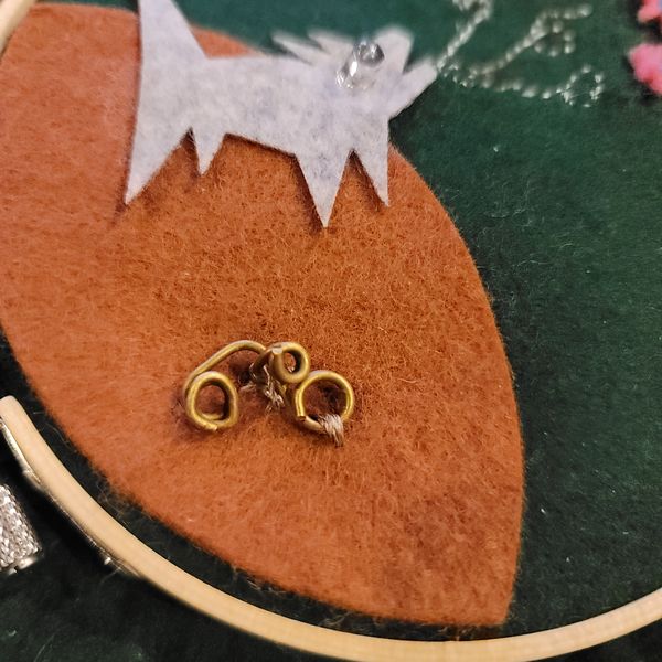
Open switch > OFF
Appendix
Experiment 3: Simple Oscillator
Simple Oscillator by Look Mum No Computer
Recently, I have become obsessed with creating Analog Synthesizers from scratch. The idea of creating a musical instrument from electronic components is an exciting challenge to me. YouTube surfing led me to the channel of "Look Mum No Computer" (LMNC).
For this electronic circuit, no microcontroller is used. It is a circuit utilizing a handful of the most simple electronic components to create a sound generating oscillator.
The transistor is configured to a 'Reverse Avalanche' mode that results in the oscillation. I still don't fully understand how this mode work.
BOM:
- 1x SS4018 NPN Transistor
- 1x 10K ohm Potentiometer (Linear type)
- 1x 220 ohm resistor
- 1x 2.2uF Electrolytic Capacitor
- 1x LED
- 1x Speaker
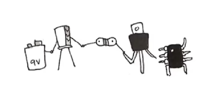
These are the circuit schematics and board layout recommended by LMNC.

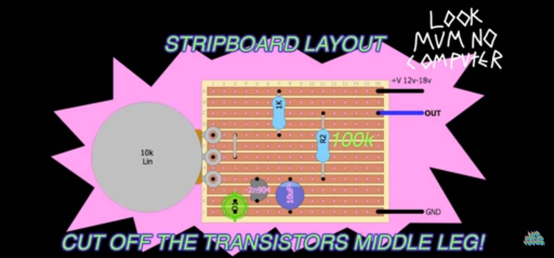
I followed his instructions and wired the circuit up exactly as he recommended...but the circuit didn't work. 2 transistors were sacrificed (eviscerated into smoke) as I tried and I tried.
Looking closely at his schematics and board layout...I noticed inconsistencies (how the capacitor is wired) and strange component positioning (the electrolytic capacitor's positive leg routed to ground). So I debugged the circuit by making component placement in a way that I believed was sensible. After many many attempts...I arrived at this successful board layout...
insert schematic & board layout drawing
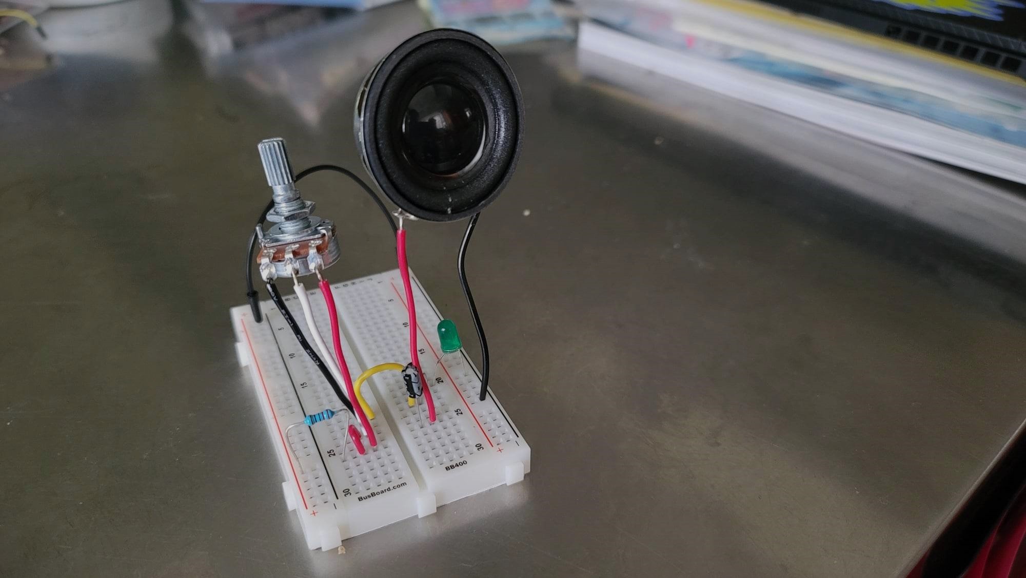
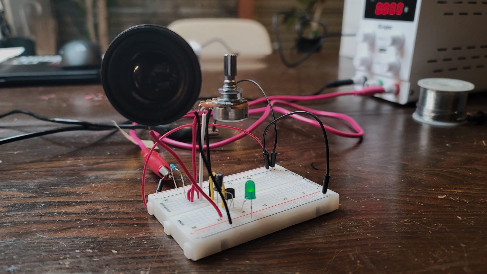
My working circuit deviated from the BOM that LMNC recommended...opting for the SS4018 transistor which avalanches at a lower voltage, a smaller 220 ohm resistor to reduce the current and protect the potentiometer, transistor and LED, and smaller capacitor to get the tone that I like (lower value = high pitch)
The Oscillator circuit as it stands is a 'Hard' interface...requiring contact and manipulation of a potentiometer to get tone variance. I thought I would try using a Light Sensor (that is also a variable resistor like the potentiometer...but activated by light) to create 'No Touch' tone manipulation. Changing the circuit was simple...take out the potentiometer, put in the Light Sensor. And I got tone...with a 'Soft' sensor!!!
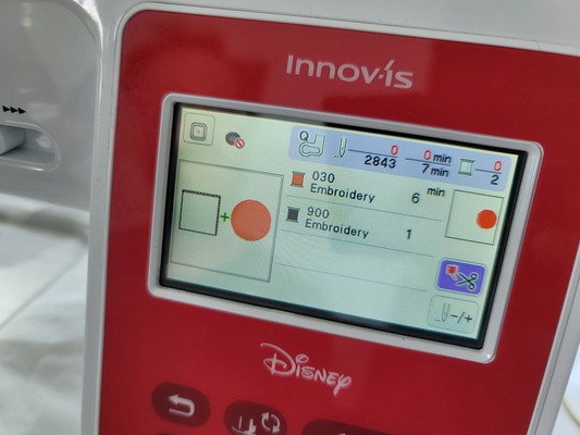
Embroidery Machine
Why are embroidery machines useful? They can sew complex, large, highly detailed work that would be EXTREMELY labor intensive and time consuming to do by hand...quickly, efficiently and repeatably.
How to use an Embroidery Machine
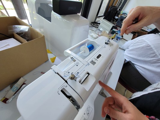
I don't really know how to use a sewing machine, let alone an Embroidery machine. I have used both before...but honestly, I cannot recall the workflow. At Fab Fest Bali, there was an embroidery machine (the Brother INNOVIS) in the Fablab, so I asked two new friends...Aaron and Leen...to teach me how to use it.
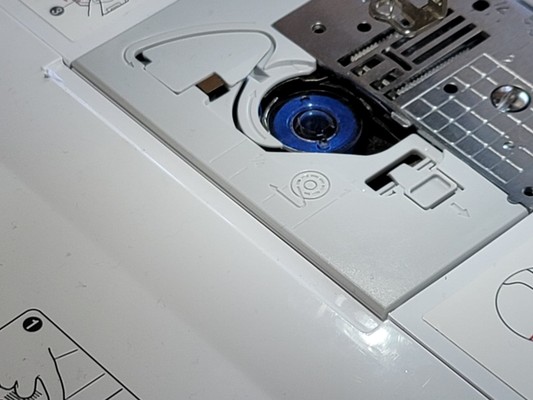
So it turns out that it was not super hard. Probably the trickiest parts was learning how to 'fill up' (that's not the right term, I know) the bobbin (the thread that come from below), installing the full bobbin in the machine, threading the needle and passing the 'top' thread into the correct pathways (just follow the numbers, it turns out). After that, it is control panel push button commands that are pretty self-explanatory.
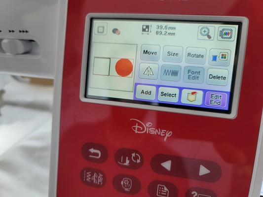
So at the end of the day, I designed a super simple graphic, 2 shapes, on Inkscape (a filled circle and and empty square). After installing the Ink-Stictch extension for Inkscape, I was able to save the graphics in the .prc format (that the Brother embroidery machine understands) on to a USB drive.
Inserting the USB drive into the embroidery machine, I could load the .prc file and then have the Embroidry Machine sew the graphic into a piece of fabric.
(insert image of embroidered graphic here)
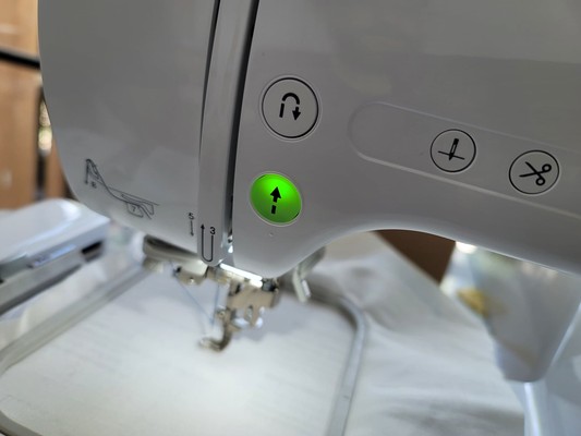
Embroidery Machine Control Panel
Where the Bobbin Spool needs to be installed
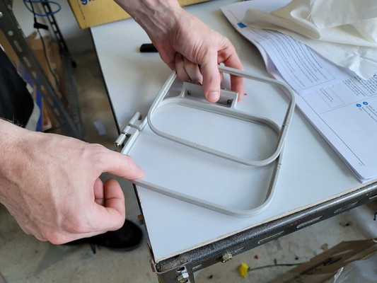
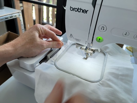
Aaron demonstrates how to stretch fabric (and backing paper) in a Stretch Frame
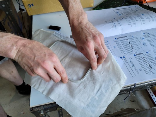
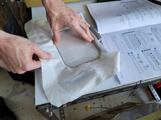
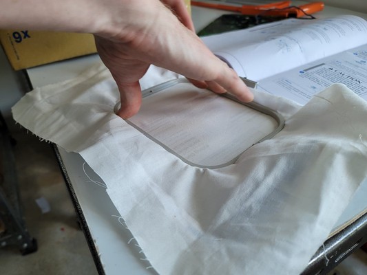
Pulling the fabric tight as you press down on the inner frame from the top
...when the fabric is stretched tight, it can function like a drum.
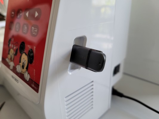
Where the USB stick containing the .prc file is inserted into the machine
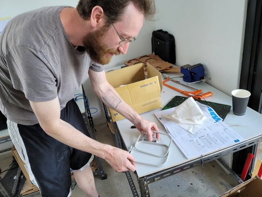
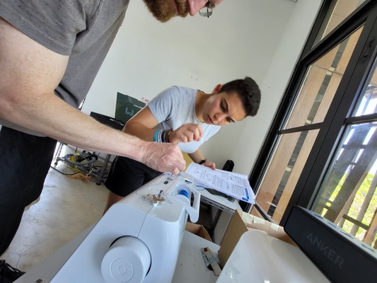
Even the pros need to read the manual to understand a new machine...
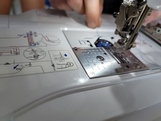
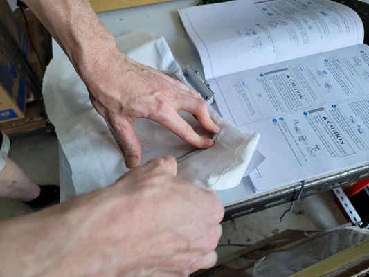
The Stretch Frame is connected to the linear motion system by hooking its 2 metal nubs into the rail's 2 catch points
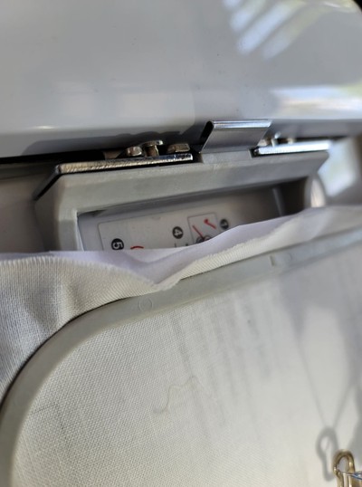
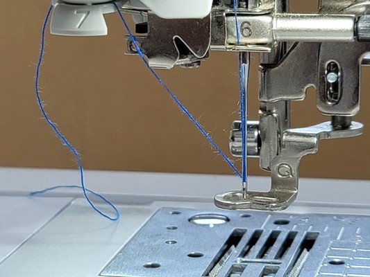
How the Top Thread is threaded through the needle's eye (number 6) and positioned off to the side (number 7)
Use this lever to lift the Sewing Foot...while threading the needle.

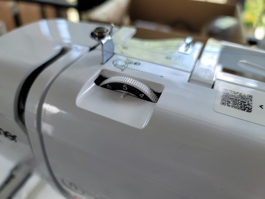
This dial sets the thread tension to the top spool. Aaron sets it so it is actually a bit loose...not taut.
Use this slider to set the speed of the embroidery operation...both together sort of functions like a CNC machine's Feeds and Speeds adjustments
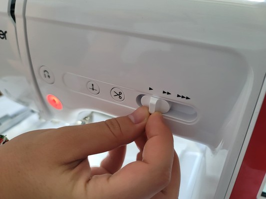
'Green Light' means go! Press to Start the embroidery process.
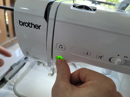
Hold the top thread as the machine begins the job...and let go a few seconds after the operation begins.
Class Notes
- Liza Stark > E-textiles
- Quilts
- Textiles speakers...low volume
- Quilt that steals your data and broadcasts it...
- Signal Lost vest...cuts off data transmission
- Textiles with conductive properties...gold thread in history
- Steve Mann (hard devices...external..."abrasivee") and Maggie Orth (soft devices...embedded)
- Embedding (integrating electronics so that it is visible...integral to the visual language and aesthetic) vs Enclosing (shoving electronics into a box)
- The soft aesthetic of electronics
- Is this a good thing? What is the meaning of this...vs the more 'brutally honest' representation of tech?
- Isn't it just image projecting without and substantive function...all image and style...?
-
Shih Wei Chieh...digital wearable with indigenous ("ancestral") culture vibe ...new and ancient at same time
-
Laura Devedorf...weaving, memory and touch
Electronics Terminology and Concepts
- Circuit...a closed loop path...for electricity to flow
- Load...a device that "uses" electricity...requires a specific amount of electricity to function
- Power Source...a 'generator' of electron/electrical flow
- Current...a stream of moving electrons
- Flow from greater to lesser electrical energy...from Power = Positive to Ground = Negative (hmmmm...is this correct?)
- Electricity flows from Power to Ground (ummmm...this is not correct)
- Electrons move in one direction...some components need to be oriented in a certain way to behave correctly within a circuit
- Voltage (Volts, V), Current (Amps, I) and Resistance (Ohms, R)
- Voltage...electrical "pressure" or "force" between 2 points (aka "Potential" or difference)
- Current...the volume of flow
- Multimeter...tool
- Resistance...the size of the pipe...the amount of flow constriction or resistance
- Ohm's Law V = I * R
- Parallel Circuit (same V, split I) vs "Series" (daisy chain...split V, same I)...connections
- Short Circuit...an unintended shorter path for electricity to move from a "Power Source's" positive to negative poles...usually instead of through a load that was placed in the circuit
Electronics Rules
- Rule 1: Electrical energy always sees the path of least resistance to Ground
- Rule 2: All electrical energy (produced by the power source) must be used...or heat will be generated or components damaged
- Rule 3: A circuit is a 'system' and different components play a different role in the system...understand which components are needed and how to arrange them (Rico...3D sculptures?)
- "Conductive" material...electricity flows through them (or not)
- Kobakant...list of conductive textiles and their properties
- Properties to consider...Resistance, Stretchiness, Solderability, Feel, Substrate + productive process
- Thread & Yarns...silver plated or spun...what resistance over a certain length...put in bobbin
- (Can I make my own conductive thread???)
- Karl Grimm thread recommended...solder OK
- Stainless Steel...high resistance, no solder