7. Computational Couture
Nearly a whole month traveling in Indonesia and Thailand. A bit behind in my Fabricademy coursework, but lots of great learning on my trip that may have applicability to what I do in this program.
Excited about this week, as I finally get to deep dive into Geometric Node Modeling in Grasshopper...something I have wanted to do for a long time.
Assignment
OK, so this week I need to...
- Design something in Grasshopper (or Blender, etc.)
- 3D print it
Research & Ideation
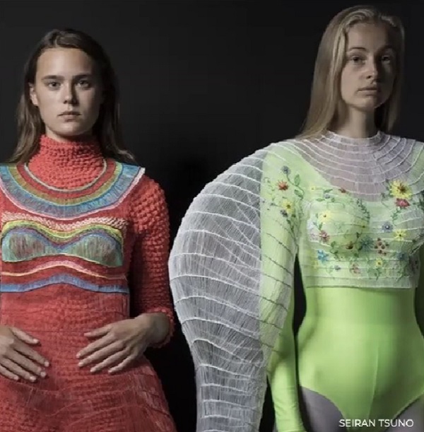
Inspiration > Behnaz Farahi
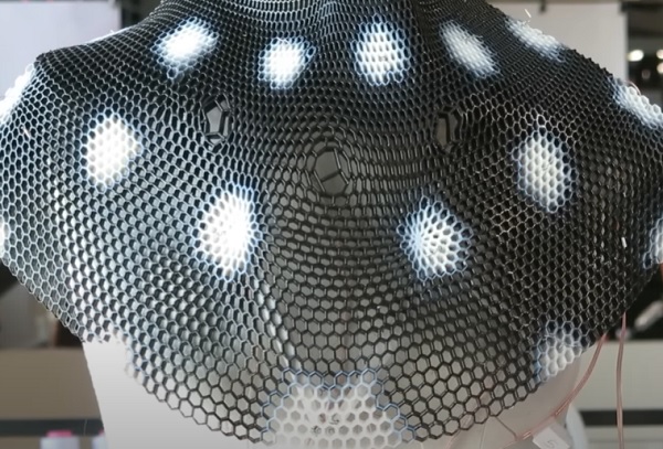
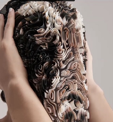
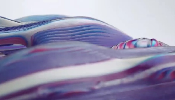
Caress of the Gaze: SMA Actuation + Multi-Material 3D Printing Electrical activation causes multi-material deformation. I have always loved this project from the first time I saw it years ago...the project is mesmerizing and beautiful. I love how Behnaz was able to make clothing that appears to be alive and responsive to the external environment and use non-traditional material as the 'textile'. I love this idea of intelligent clothing fabricated of non-traditional materials...that also sends a poignant message.
Tons of other inspirations are in my class notes at the bottom of this documentation.
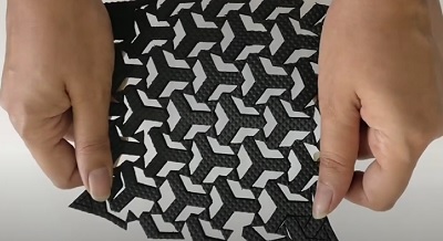
Auxetics
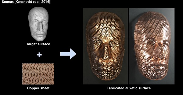
Auxetics = "...structures or materials that have a negative Poisson's ratio. When stretched, they become thicker perpendicular to the applied force...Such materials and structures are expected to have mechanical properties such as high energy absorption and fracture resistance." (wikipedia)
Auxetic Structures Research - Timar
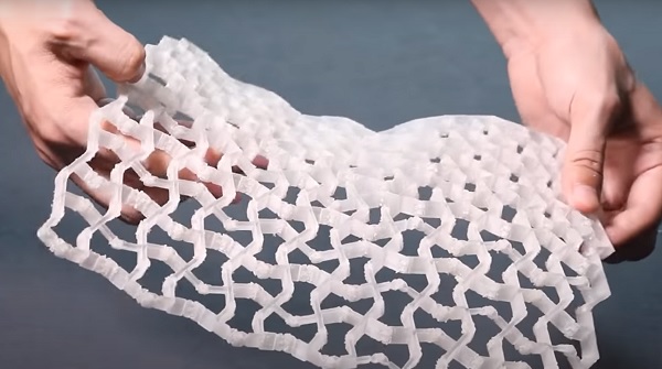
I am very attracted by this 3D deformable and elastic surface. I particularly like that in 3D form, Auxetics are useful as cushions...such as for shoes.
Note: Can 'Infill' generated by 3D Slicer software be used as a simple Auxetic structure?? The only modeling that would be required would be the general outer form of the object.
Auxetics & Metamaterials (+Grasshopper Tutorial)
- A 'thick' soft material can be cut in a vinyl cutter (??)
-
2.5D Surface with multi-directional flex and spring-force return
-
3D Structure with multi-directional flex
Linketix plugin for GH...allows creation of Auxetic surfaces.
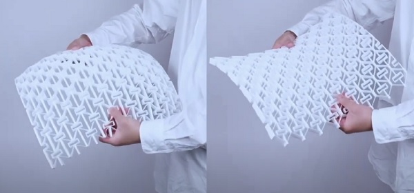
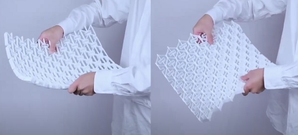
3D Printing Auxetic Material - Two Minute Papers
 source: Konakovic, 2016
- Conformal Mapping...allows auxetic surfaces to be mapped on to complex contours, i.e. face
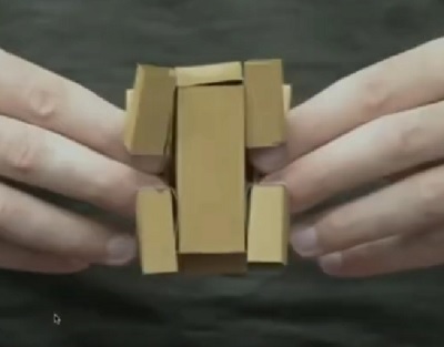
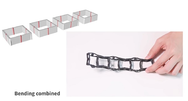
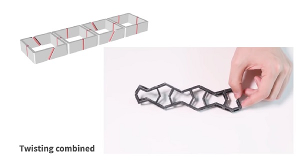
kinetiX-designing auxetic-inspired deformable material structures showing research by the Tangible Media Group, MIT
Rigid structure with elastic hinges...allows for deformation when force applied and return to original shape when force relaxed
3D Printing Techniques
Infill Printing without Walls
- Use infill >25%
- Remove walls in Slicer by removing vertical walls
Non-Planer 3D Printing
- True 3D Printing/Non Planar Slicing
- Non Planar 3D Printing by Bending GCODE
Under-Extrusion
Print to Fabric
Flexible Filament
Bio Material Printing
Gel Printing
Self Folding Origami
Assignment Work
Previous Related Work
Programming and parametric modeling are not new concepts to me...but I have never taken on what at first appears to be the daunting task of doing so for clothing fabrication.
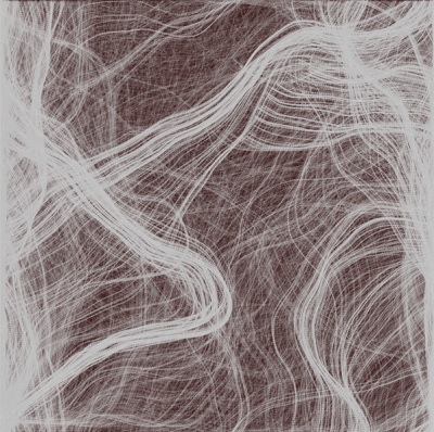
In the past, I programmed a Perlin Noise Field Flow in P5js. Computational random flow lines...with the appearance of textile. I wonder if the result could be converted into 3D printing paths somehow?
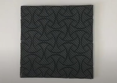
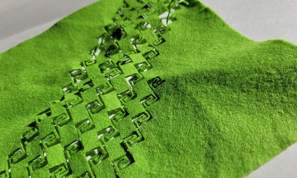
To test a lasercutter, I once cut a flexure pattern that I laser cut into felt...allows the felt sheet to be elongated in several directions in surprisingly interesting ways. The pattern was downloaded from the internet, but I am sure that it can probably be created in Grasshopper somehow...to make a flexure surface.
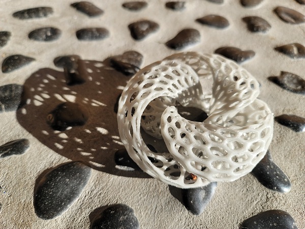
I had also 3D printed a voronoi geometric object made in Blender ...following the documentation of Nadieh Bremer, a Fab Academy student at the Waag. Unlike Grasshopper that uses a node-based schematic to generate geometry, Blender uses geometric modifier commands to distort a sphere (the initial input geometry) into this final shape (the final output geometry).
To prepare to produce this week's assignment work, I did a TON of Grasshopper tutorials, which is documented at the bottom of this assignment page.
Virtual Fashion in Blender
Found this amazing tutorial video...Modeling Fashion in Blender. I will work through this video to learn the techniques...
3D Printing on Fabric
Inspired by classmate Dinesh...
Auxectic Flip Flop
Not a lot of time to do the actual assignment work. A nasty cold and a whole bunch of Grasshopper tutorials burned a lot of time. As I became fascinated by Auxetic structures, I thought I would explore it for its elastic/cushioning properites and make something simple...a Parametric Flip Flop.
The plan...
- Design the 3D Auxetic structure in Grasshopper...make it parametric so the size can change
- 3D Print the test structure
- Make the 3D Auxetic structure into the shape of a Flip Flop sole
- 3D print the Flip Flop sole using flexible resin
- Attach scrap fabric to make the foot loops
I know that making a lattice shoe sole is possible because it was demonstrated in this video. I just have to learn how it is done!
Process and workflow
I will model something like an Auxetic Structure (a 3d Voronoi lattice) in Rhino and Grasshopper, based on this YouTube tutorial Voronoi 3D + Multipipe. I figure that before I can make a 3D Auxetic Lattice, I should probably learn how to make ANY lattice in Grasshopper first!
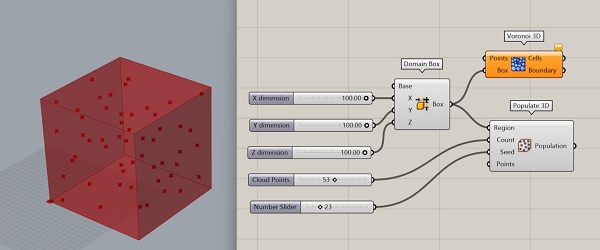
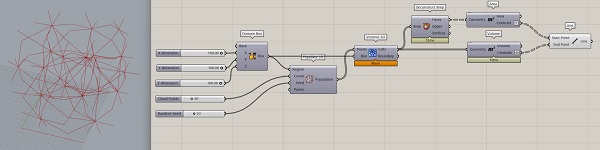
Step 1 > Bounding Box
- Begin with a Surface/Primitive/Domain Box component & several Number Sliders for XYZ adjustments
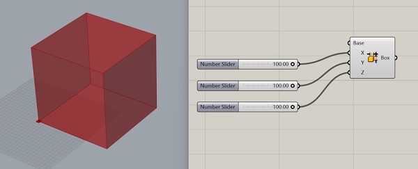
- This Box will serve as the boundaries for the Voronoi lattice to be created
Step 2 > Cloud Points
- Add a Mesh/Triangulation/Voronoi 3D component
- Add a 3D Geometry component to generate a cloud of random points within the Bounding Box
- Add a Number Slider to control the number of 3D Geometry points and another to generate the Random Seed value
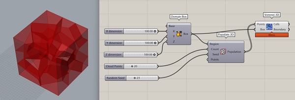
Step 3 > 3D Voronoi
- Connect the output of the 3D Geometry component with the Points input of the Voronoi 3D component...to generate the Voronoi structure inside the Bounding Box
 ...
...
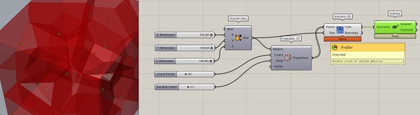
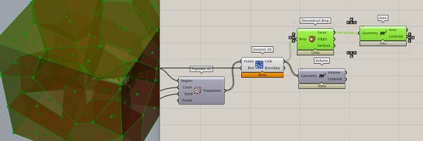
Step 4 > Cell Centroid
- Add a Surface/Analysis/M3 component...connecting its Geometry input with the Cells output of Voronoi3D
- The Centroid of each Voronoi cell will appear as a point
Step 5 > Cell Faces Centroid
- Add a Surface/Analysis/Deconstruct Brep component...connecting the Cells output of Voronoi3D with the Brepinput...to define the faces of each Voronoi cell
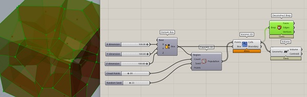
- Add a Surface/Analysis/M2 to find the Centroid of the cell Faces...Simplify the Centroid output
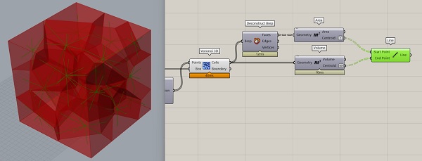
Step 6 > Line Connections
- Graft the Centroid output of M3
- Add a Curve/Primitive/Line component...connecting the output of M2 with the output of M3
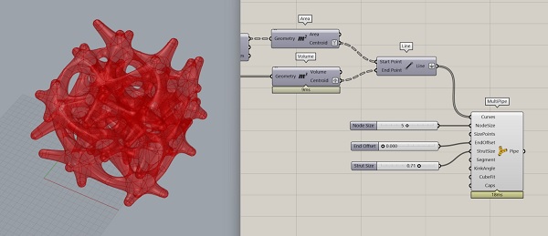
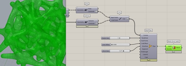
Step 7 > Multipipe
- Flatten the Line output
- Add the Surface/Subd/Multipipe component...connecting the Curves input to the Line output of Line component
- Add Number Sliders for...NodeSize, EndOffset, StrutSize
- Rt-Click on Caps and chose Round to close the ends of the Multipipes
Step 8 > Convert to Mesh
- Add Surface/SubD/Mesh from SubD component
- Add a Custom Preview and Colour Swatch component to visualize the model
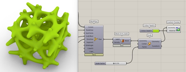
Step 9 > Bake to Rhino
- Add Scale component to be able to adjust the size of the model
- Check the scale of the model
-
I followed these fantastic instructions to correctly export my model at the right size.
Exporting Models for 3D Printing from Grasshopper -
Rt-Click to Bake the model for use in Rhino
Step 10 > Export STL
- In Rhino, type Export...choose a file name and select STL (binary) as output file type
Step 11 > Slice STL
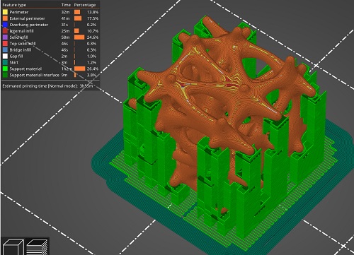
Prusa Slicer for FDM printing
Print Settings:
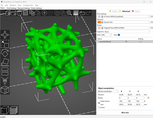
- Layer Height: 15mm
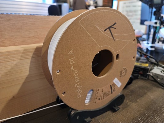
- Filament Material: PLA
- Printer: Prusa Mini
- Supports: At Enforcers Only
- Infill: 20%
- Brim: yes
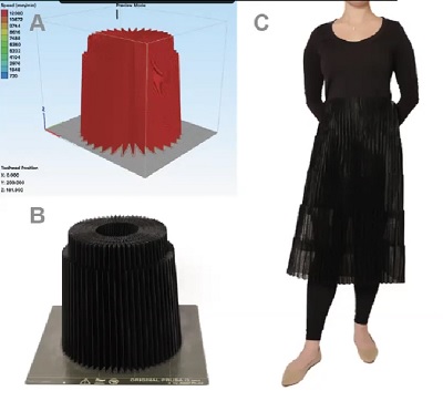
I thought about it and did not think that I could print the Voronoi Cube without supports. I really hate how much plastic is wasted by printing supports. So to keep supports to a mininum, I chose to place support points in specific 'vulnerable' positions (similar to the way resin printer supports are placed). Point supports from the build plates for overhang 'nubs' and 'cross bars' using Prusa Slicer's Paint on Supports tool.
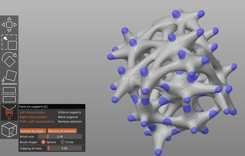
Sliced for printing: 4hr print time and unfortunately...26.4% of the PLA material used will be for printing supports.
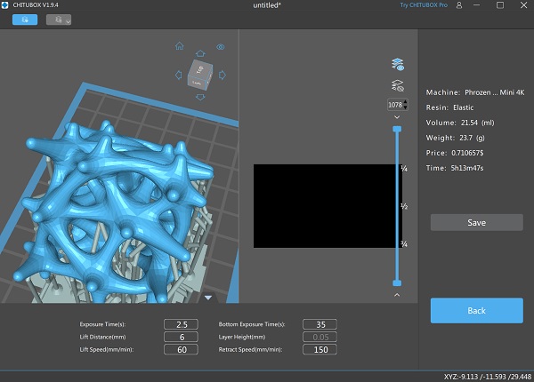
Chitubox slicer for Resin Printing
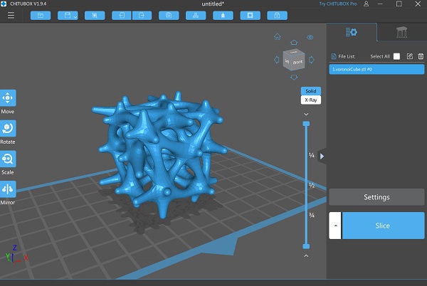
After importing the model into Chibox and before slicing, there is a standard procedure to follow to help guarantee a successful resin print.
-
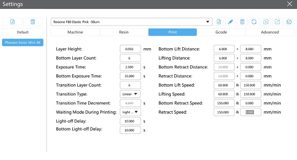
In the Settings menu...choose the correct Printer Profile (Phrozen Sonic Mini 4K) and Print Settings
-
Do not have the model sitting flat on the build plate...rotate it 45 degrees
- Specify supports for the model...I chose to go with Medium Supports (easier to remove than Heavy supports) at 70% density
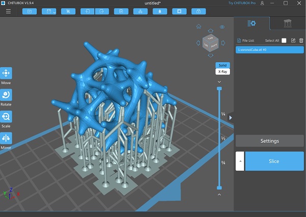
With the settings complete, the model can be sliced...5hr and 11mins print time...using 21.54ml of resin
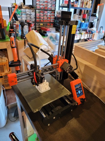
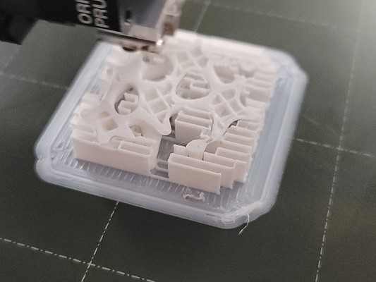
Step 12 > FDM Print
Prusa Mini
Polyterra PLA > White
Step 13 > Resin Print
- Phrozen Sonic Mini 4K
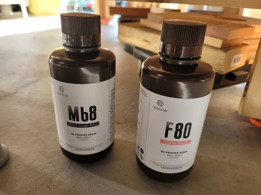
- Resione F80 Elastic Resin > Pink with...
- Shore hardness: 50 to 60 A
- Tensile Strength: 3.8 MPa
- Tear Strength: 9.75 KN/m
- Breaking Point Elongation: 159%
- Viscosity (68F/25C): 2,300 mpa.s
- Elasticity: 1.8 MPa
- Print Settings
- Layer Height: 0.05mm
- Initial Layer Exposure Time: 35-50s
- Exposure Time: 1.7-10.2s
- Wash & Cure
- Soft brush, ultrasonic cleaner > 3mins
- 95% IPA
- 385-405nm UV > 4-6mins
The slicer software stated that 21.54ml of resin would be required to print this model. To be safe, I decided to pour a bit extra.
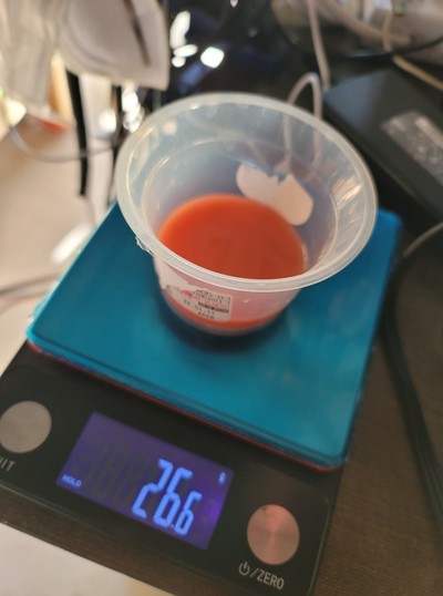
Moreover, I have read that resins can be mixed to change their properties. So instead of just using Resione F80 (Elastic), I also added about 10ml of Resione M68 (Hard)...with the idea to reduce the elasticity of the final result a bit.

The resin mix was poured into the Resin Printer vat with only light mixing effort...going for the marbled effect. Fingerscrossed that this experiment ends well.
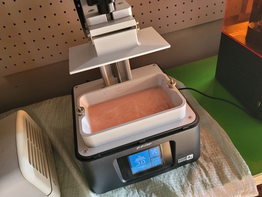
Everyone says that elastic resin is hard to work with. It is extremely viscous and requires a minimum temperature of 25C to print properly.
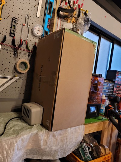
Since the avg daytime temperature in Japan is less than 25 degrees and it likely to drop as we head into evening...I created a cheap-and-cheerful heating chamber for my little printer.
 .
.
Addendum:
After several failed prints, I Googled suggested exposure time for my printer and resin...and surprisingly found it here.
So I needed to have these settings...
Layer Height: 50um
Exposure Time: 3s
Base Layer Count: 3
Base Exp. Time: 40s
Light Off Time: 10s
I also found this video on the Resione f80 resin.
- need longer exp time
- use heavy supports
and the Resione Office Page
with downloadable support settings and printer config files
The Printing Outcome
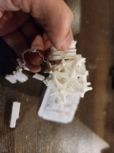
Here are the results from the FDM printer...
3hrs and 56mins later...
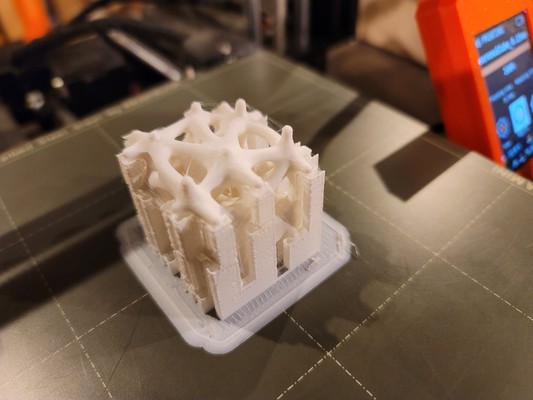
The Point Supports were really easy to remove and successfully supported the model where it needed!!
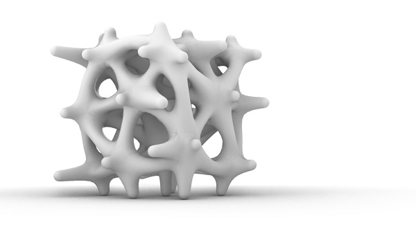
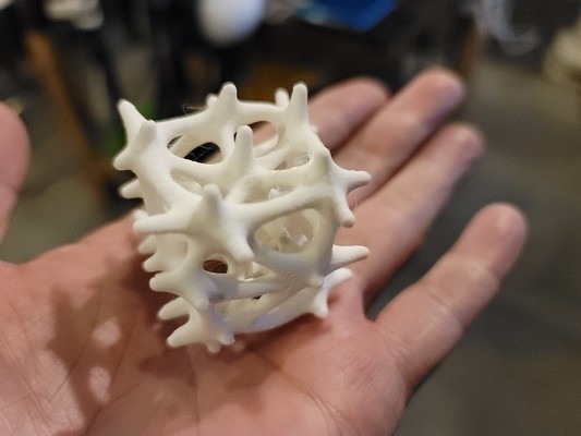
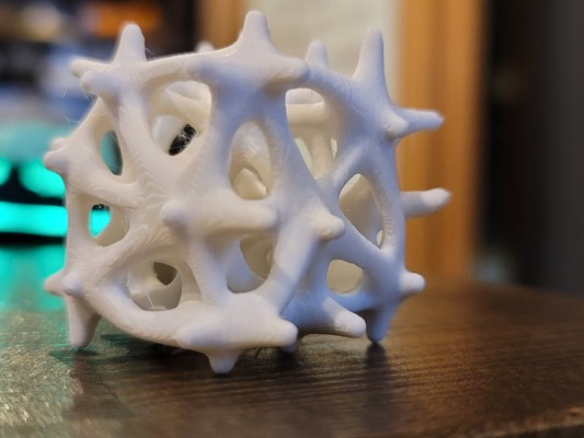
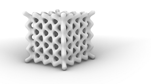
The final print looks great! Printed in white...the Voronoi Cube looks like a piece of coral!
...and Resin Printer.
First attempt...failed. I think the heater turned OFF at some point and the resin got cold...and stopped adhering to the build plate.
Auxetic Flip Flop
So, with the 3D Voronoi Lattice successfully modeled and printing, the next step is to model an Auxetic Lattice...and do so using a shape that looks like a Flip-Flop sole...not a cube...as the Bounding Box.
- In Rhino, use the Control Point Curve tool to make the outline shape of the Flip-Flop sole...approximately 27cm long and 12cm wide.
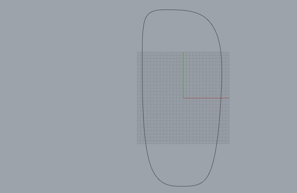
- Launch Grasshopper to Parameterize the rest of the model
- Add Curve component...and set to the curve
- Add a Scale component and Number Slider that allows the sole size to scale between 0.00 and 2.00...with 1.00 being 27cm long and 12cm wide
- Add a Extrude component to turn the 2D curve into a 3D form
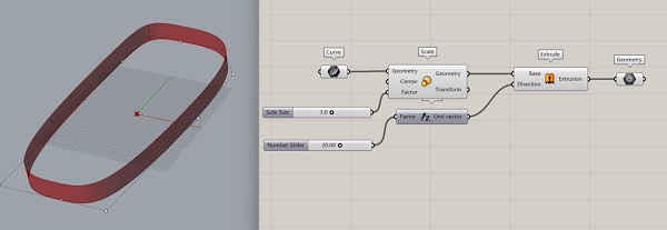
- Reuse the node script used above for the 3D Voronoi Lattice...substituting the Flip-Flop Geometry for the Domain Box
- Results in partial success...the point cloud is contained in the Z direction...but not in the XY direction.
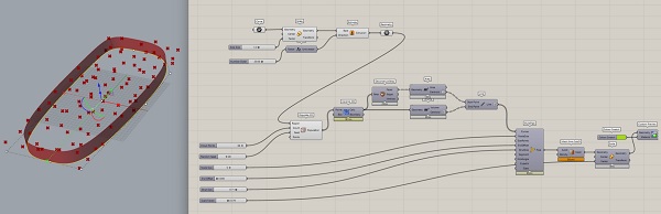
Made some adjustments...
- Turned the Flip-Flop sole into a surface by adding a Boundary Surfaces component to place in between the Curve and Scale components
- This ensured that the Extrude component creates a 3D volume...not just a 3D extrusion of the curve.
- Replaced Populate 3D with Populate Geometry
- An improvement...the points are contained in the Flip-Flop sole volume.
...but the lattice extends beyond the boundary. The Voronoi 3D component still uses a rectangle as its boundary...rather than the round shape of the Flip-Flop sole.
Watched this video by Architutors...to find the solution. Looked promising...but it didn't work for me. Will need more time to figure this out.
Flip-Flop put on hold...
12hrs later...
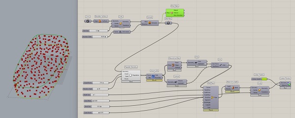
Searching the internet, I found this post on Voronoi 3D in Grasshopper. One respondent suggested using Proximity 3D rather than Voronoi 3D to generate the lattice. I tried it...and it seemed to work...but sadly, no.
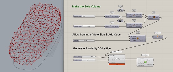
The lattice appears to be contained in the Flip-Flop shape...but unfortunately, it is not a 3D lattice. The lattice is only on the surfaces of the sole.
Theory: I think the issue has to do with the fact that the sole shape is a Brep...and not a true volume. That is why both Proximity 3D and Voronoi 3D has trouble with it.
Googling 'Brep to Volume'...found this thread > Voronoi in Irregular Volume with a promissing solution (it seems my question is a common one for newbie GH users).
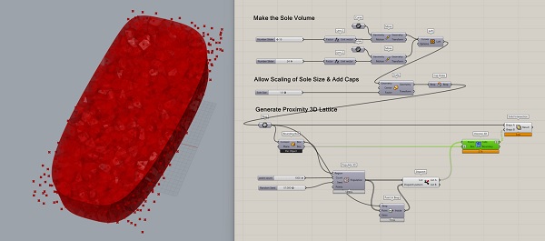
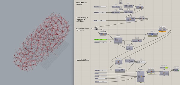
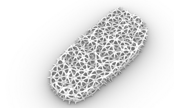
...then adding the MultiPipe component and associated nodes...and...SUCCESS!!! (insert dance of joy here). It doesn't look particularly comfortable...and I don't fully understand what all those extra node components did to solve my issue...but I am darn happy with the progress!!!
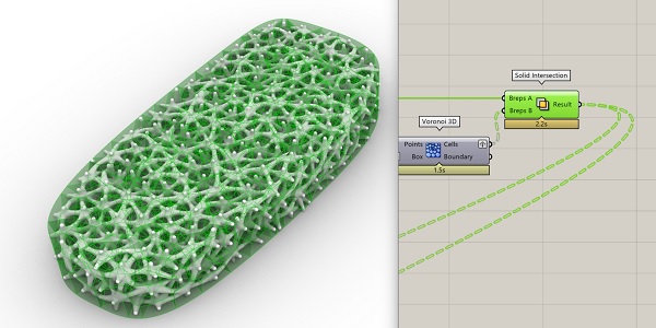
So there were 3 components that were added that made the difference...Point in Brep which obviously specified which point was inside (vs outside) the Brep Sole shape; Dispatch which takes input from both the Populate 3D component that generates points within the rectangular Bounding Box and the Dispatch component that has a list of points that are within and without of the Flip-Flop sole Brep shape; and Solid Intersection that uses the Flip-Flop Sole shape to 'cut' the 'corners' off of the rectangular Voronoi lattice...leaving only the sole shape.
Next Steps
- Add Attractor Curve to make the lattice denser where the foot presses down
- Cut Strap Holes into the Lattice for insertion of Foot Straps
-3D print the Voronoi Lattice Flip-Flop sole...using Flexible filament or resin...to test real-world functionality - Substitute Voronoi with Auxetic pattern (gotta learn how to do this in GH!)
Garment Simulation in Blender
I discovered this amazing instructional video on YouTube showing how to use Blender to simulate clothing.
Digital Fashion in Blender by Veryveig
I have some experience with Blender and am aware of its powerful physics engine. But working through this tutorial, I was able to play with the software's cloth physics for the first time. At the end of the tutorial, I was able to 'dress' my animated virtual model with my rudimentary garment and see it drape beatifully...although I had an uncorrectable issue with my model walking through his garment when walking motion was applied. While I have some debugging to do...this Blender experience really gave me a good understanding of how Digital Simulation can be used to prototype garment design concepts and help reduce waste textile scrapes that would be generated from physical prototyping.
Beginning with a Mesh Plane and applying Cloth Physics
(...add images of Cloth modifier and physics settings)
Create a rudimentary 'Pattern' that will be used to make a simple shirt
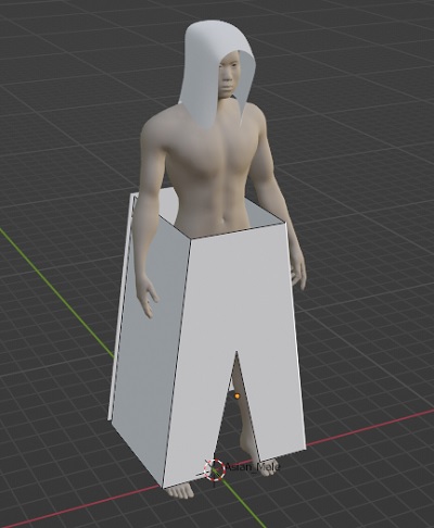
Pants
Fabrication Files
3D Models
Voronoi Cube model
Appendix: Grasshopper Learning
While a bit old and a bit long, I found this Grasshopper tutorial very helpful in getting an initial understanding > Rhino Grasshopper Tutorial (Beginner)
The Concept of Grasshopper
Grasshopper is a Rhino plugin...adds node-based, procedural geometry manipulation functionality to Rhino. Launch Grasshopper in Rhino by typing 'grasshopper' at the Command Line...or clicking the green-sphere 'Launch Grasshopper' button.
Visual Programming
Grasshopper...is Visual Programming that basically involve connecting a series of functional nodes or 'components'. Simplistically, a Grasshopper program consists of an Input Node an Output Node and a bunch of Modifier Nodes in between. The Input Node is usually some geometry made in Rhino that the user wants to apply parametric transformations onto to generate a unique Output result. Grasshopper adds easy to adjust Parametric modification functionality to Rhino geometry.
Modifications made in Grasshopper to Rhino geometry is Non-destructive (i.e. can be easily reversed) until it is permanently Baked onto the original geometry. That is, manipulations and modifications to the original geometry can be explored and adjusted until a desired result is achieved...before fixing the changes to the original geometry.
Component Nodes
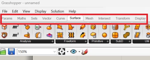
Grasshopper's functional nodes or components are organized into functional tabs at the top of the Grasshopper interface. Default tabs include...Parameters, Maths, Sets, Vector, Curve, Surface, Mesh, Intersect, Transform & Display.
There are many Plugins (Node Sets) to Grasshopper that increases its functionality and ease-of-use. Plugins can be found at food4rhino.com.
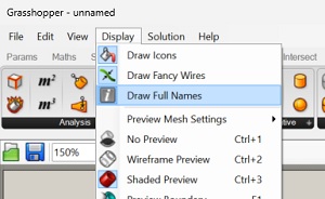
Bifocals plugin, for example, displays the component/node names as floating labels...making them easier to identify. Drag the Bifocal component onto the work area to make it active. Additionally, two toggles should be activated to make component identification super easy...Display > Draw Icons and Display > Draw Full Names.
-
Other useful plugins...Lunchbox, Weaverbird
-
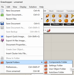
Grasshopper plugins are stored in File > Special Folders > Components Folder.
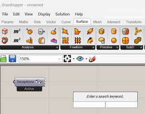
- Press the Spacebar or Double-click the mouse in the Grasshopper window brings up a Components Search window.
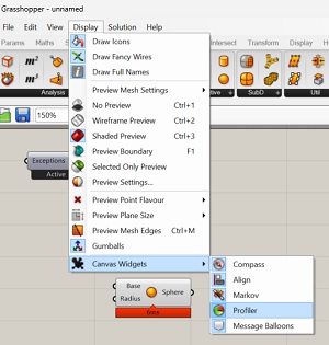
- To make the Processing Time Required for each components, togggle...Display > Canvas Widget > Profiler.
- To add a Number Slider...simply Double-click in the Grasshopper window and type a number.
- To specify a range of numbers for the Number Slider, type the first number, then 2 periods, then the second number, a period and the desired number of decimal points.
Connnecting Wires
Toggle Display > Draw Fancy Wires to show different variants of connection wires between nodes. There are 3 variants...
- Single line (one data item)
- Double line (one list of data items)
- Dotted line (multiple lists of data items)
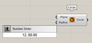
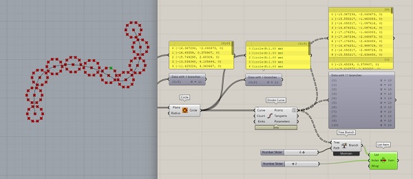
To connect several wires to the same input, hold down the SHIFT key as the additional connection is made. In this example, 2 circles are made with one Circle component.
- Disconnect wires by holding down the CTRL key while clicking the output and input connectors
Panels
Used to see what is happening at the node Output...to see the data item being outputted. Useful for debugging, understanding what data is being generated by component nodes...similar to a Console window or Serial Monitor in programming.
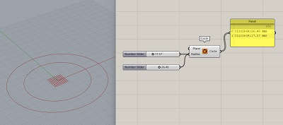
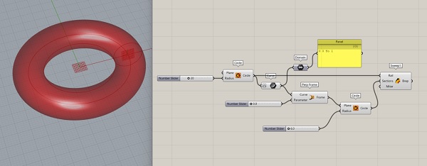
Tutorial 1 > Donut
Geometries can be made in Grasshopper to show virtually in Rhino...until baked (right-click on the geometry node > bake > choose Layer)
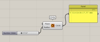
- Make a Circle
- Define a radius for the Circle with a Number Slider node
- Add a Param/Curve...and Right-click Reparameterize to range of 0 to 1
- Add a Perpendicular Frame component
- Add a primitive Domain (display numerical range) component & a Panel
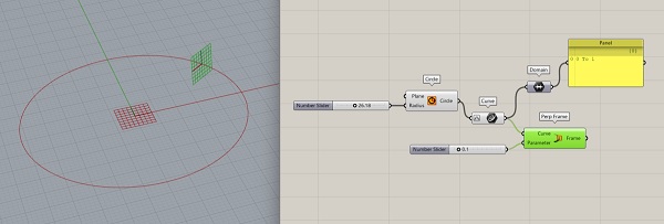
- Change the Perpendicular Frame size in...Display > Preview Plane Size
- Add a Curve/Circle to the Perpendicular Frame...connect Frame to Plane
- Add a Number Slider to specify the Circle size
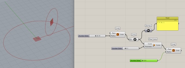
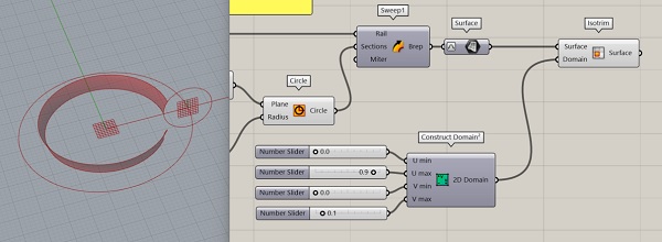
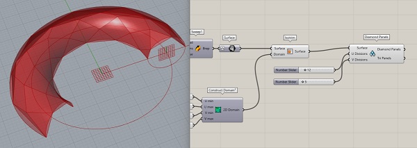
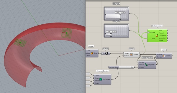
- Choose Surface/Freeform/Sweep1
- Sweep the perpendicular circle Section using the first circle as the Rail
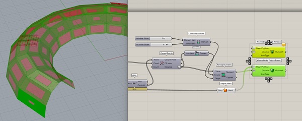
- Add Surface/Util/Isotrim...connecting Sweep's Brep output to Isotrim's Surface input
- Add a Param/Surface node and Reparametize (rt-click) it
- Add Maths/Domain/Construct Domain2 component (for objects with two domains)...adding Number Sliders for U min, U max, V min, V max
- Turn off Preview (rt-click) for Sweep and Surface
- Observe how the U and V domains are generated and controlled by adjusting the 4 sliders of the 2D Domain modifier for Isotrim
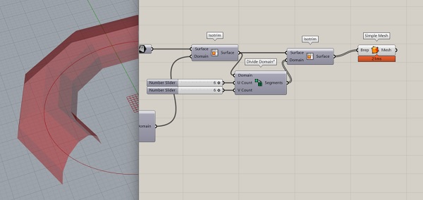
- Add another Isotrim and Divide Domain2 component nodes...to segment the 3D curve into connected panels
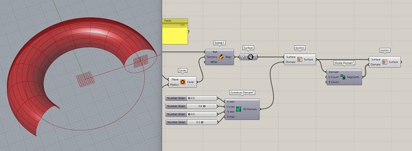
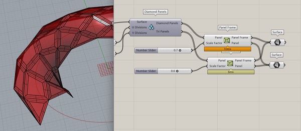
- Use Lunchbox plugin's Quad Panel (for flat panels) or Diamond Panels (for diamond shaped not rectangular panel shape)
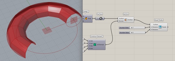
- Make Frames for each panel using Lunchbox/Generate/Panel Frame adding Number Sliders to control the Scale Factor input
- Connect the result to a Param/Surface component and bake onto a Rhino layer called 'frame'
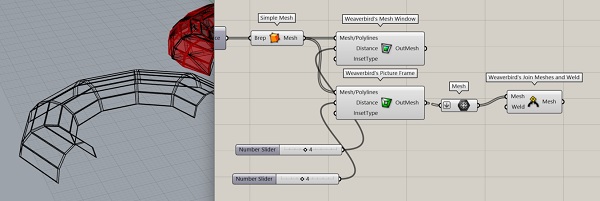
- Convert NURBS (UV) Surface to Mesh using the Mesh/Util/Simple Mesh node
- Toggle Display > Preview Mesh Edges
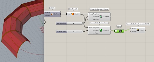
- Weaverbird can also be used to create Frames...from a Mesh
- Add Weaverbird/Transform/Mesh Windows node & Number Slider
- Add Weaverbird/Transform/Mesh Frames node & Number Slider
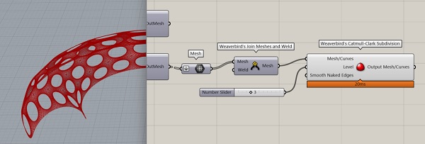
- Add Flattened Mesh and Weaverbird/Extract/Mesh & Weld to make frames into one object...rt-click Set Boolean to True
- Bake to create a frame geometry object in Rhino
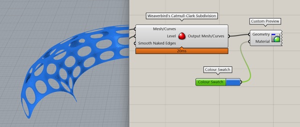
- Add Weaverbird/SubD/Catmull-Clark Subdivision to generate round holes instead of square frames
- Coloring Grasshopper objects with Display/Preview/Custom Preview & Color Swatch component nodes
- Reversing an Input Value by rt-clicking on the Input Name > Expression > Enter -x in the Expression Editor
Adding a Point Attractor on the surface of the NURBS surface.
- Add Surface/Analysis/Evaluate Surface node...Reparameterize the Surface input connector
- Add 2 MD Slider nodes...a multi-dimensional UV surface point selection tool
- Add 2 MD Slider nodes...a multi-dimensional UV surface point selection tool
- Find the center of surface panels with the Surface/Analysis/Area node
- Add a Closest Point (CP) node
- Connect Centroid to CP Point and ES Point to Cloud
- Scale the CP Distance to 2 and 10 by adding the Maths/Domain/Remap Numbers & Maths/Domain/Bounds & Maths/Domain/Construct Domains component nodes
- Connect the scaled Remap Number Output to the Distance Input of the geometry frame and windows...but also have to graft the Distance & Mesh/Polyline Inputs...to have them affected simultaneously
Tutorial 2 > Eugenio Bettucchi
Day 1 > Grasshopper Basic Overview
- Rhino interface & basic commands
- Command line & Log Console...at the top
- Viewport...where the modeling occurs
- Tool menu...to the left, various drawing tools
- Workspace Tabs...below the command line
- Cursor Arrow without stem = in a command, use ESC to exit command
- Double-click on Viewport Window name to make it fullscreen
- Typically: Use Rhino to export geometry to Grasshopper
- Launch Grasshopper by typing it into the command line...or cliking on the green sphere icon
- Grasshopper can work with geometry...and data
- Right-click on or outside the component...is different
- Right-click on element to associate it with selected geometry in Rhino...set to one or multiple components
- List order is determined by order the geometry was generated
- Grasshopper assigns an Index number to every element...Index starts from 0 not 1
- Grasshopper is non-destructive to original geometry
- Input, Output...and modifiers in between
- Can remove components from calculation...speed things up
- Recover from crash...auto-save: file > Special Folder > Autosave Folder
- Recommended: Can have one Rhino file that contains several saved grasshopper files...ex: shape generation, testing, fabrication grasshopper files
- Install plugins: 2 ways
- Rhino > Package Manager
- Food4Rhino website > Grasshopper Apps...require registration for downloading
- Download .exe file...run file to install
- Can download .gha file too...install by moving into Grasshopper's libraries folder
- Some plugins will require an 'unblock' in the properties of the .gha file
- Restart Rhino after install...to get access to newly installed plugins
Basic Operations
-
Eugenio recommended Grasshopper Plugins > Weaverbird, bowerbird, Chromodoris, lunchbox, mesh Edit, mesh tools, bifocals
-
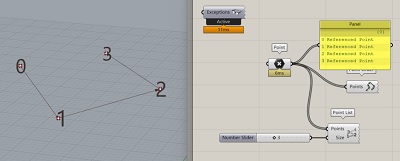
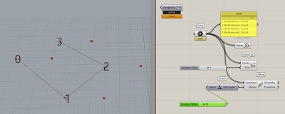
Point List component...visually identifies the index number of geometric elements in Rhino...no Output connectors
- Point Order component...shows connection between the points
- Move component...moves geometry, requires a directional vector
- Unit X component...for example, is a vector for the X direction only
- Bake = send grasshopper operation back to Rhino...a specific layer can be chosen
- Every time you Bake...new, duplicate geometry is created
- Disable is different from Preview Off...because it prevents calculation, not just hide from virtual display
- Scribble component to write text notes on the Grasshopper viewport
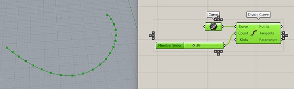
- Divide Curve component...draws a desired number of equidistant points along a curve
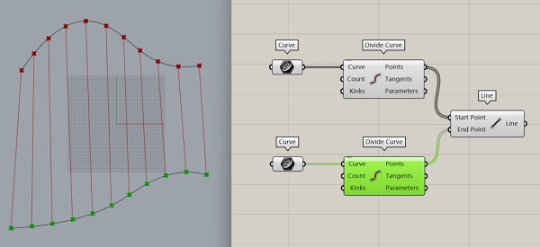
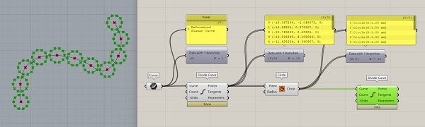
Drawing a Surface from 2 Curves
-
grasshopper...has no scale...borrows scale from Rhino...make sure Rhino units is set correctly File > properties> units
-
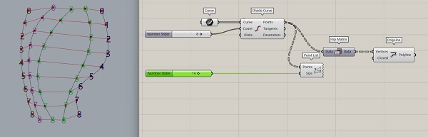
Make 2 Param/Curve components...set them to 2 drawn curves in Rhino
- Add 2 Curve/Division/Divide Curve components
- Add Curve/Primitive/Line component...to connect the division nodes of one curve to the others
-
Use Flip Curve in Rhino to revese the order of the division points of a curve
-
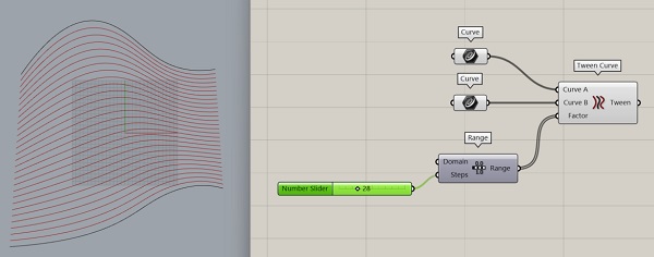
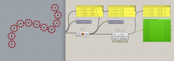
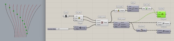
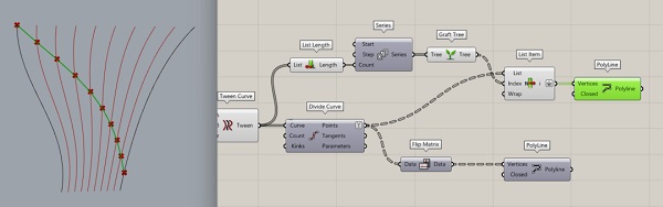
Use the Tween Curve component...to generate extrapolated curves between the orignial 2 curves
- Add the Set/Sequence/Range component...to specify how many intermediate curves to be generated (why can't we just use a Number Slider?)
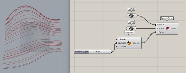
- Instead of Range the Sets/Sequence/Random component can also be used to create an interesting effect
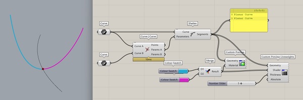
Splitting a Curve
- Use the Intersection/Physical/Curve-Curve component...to specify the intersection(s) between 2 curves
- Add Curve/Analysis/Evaluate Curve to find any point along the curve...Reparameterize the Curve input...to set the value range from 0 to 1
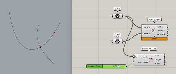
- Break the curve with Shatter component...using the Output from the curve to be cut for the Shatter/Curve Input and Param A Output from Curve-Curve as the Input for Shatter/Parameter
- Color code the different segments using Display/Preview/Custom Preview & Color Swatch
- Add the Merge component to merge the 2 colors of the 2 segments together
- rt-click on element connector letters...to access its context menu
- Create custom views with setview > named views...to create custom display ports in Rhino
- Use ViewCaptureToFile command to export the view as an image file...specifying resolution...recommend to Scale > 2
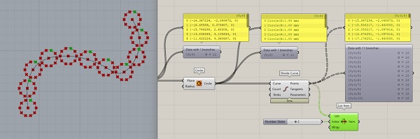
- Use Sets/List/List Items and a Number Slider to select a specific item from a data list
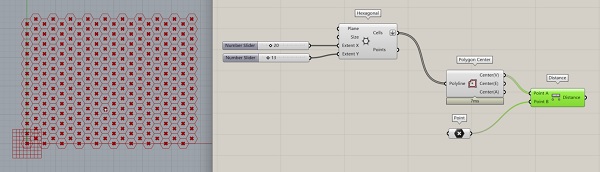
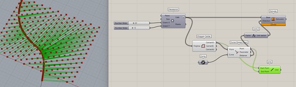
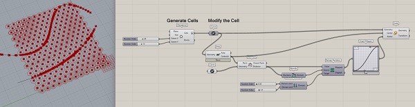
Attractor Point
- Add a Vector/Grid/Hexagonal
- Add a Polygon Center component to find the center to all the hexagonal cells
- Add a Param/Point component as an attractor point
- Add a Distance component to measure the distane between the attractor point to all the center points of the hexagonal cells
- Add a Vector/Vector/Vector 2 Point component & Display/Vector/Vector Display Ex to show the vectors
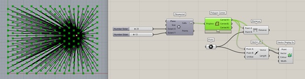
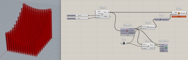
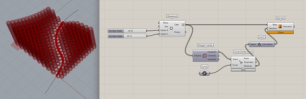
The distance information from each cell center to the attractor point can be used as inputs to something else...like color gradient or extrusion
- Add Extrude & Unit Z & Number Slider components...connect to the vector distance output.
Attractor Curve
Similar to Attractor Point, just some changes as to how distance is computed.
- Exchange Curve Closest Point for Distance & Distance to Point and Param/Curve for Point
- Reverse the extrusion effect by adding Remap Numbers
- Bounds components...defines the smallest and largest number in a random list of numbers
- Add construct Construct Domain
- Simply reverse the inputs to Construct Domain to reverse the impact
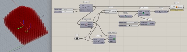
Alternatively...use Pull Point instead of Closest Point...much simpler.
Day 2 > Data Tree & Fabric Simulation
- Kangaroo is a plugin that adds physics to geometry
- Display > view fancy wires
- Param Viewer component
- Flatten > consolidates a data tree into one list
- The Sets menu deals with Data Tree
- working on LIST or TREE? Must know...
- Simplify used to collapse operational levels to one
- Isolating the branch and specifying an item using the Tree Branch component to isolate a branch
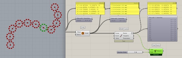
- Then List Item to isolate the item within the branch
- Manipulating Index: List, Cull, Partition
Working with Data Tree Lists
- List Length = returns the array length
- List Item = used with Number Slider, returns the value at a specific Index value
- Cull Index = deleting or removing the index value specified
- Partition List = to break a list into desired partitions (creating branches??)
- Tree Branch = to select a specific branch...can be used in combo with List Item to find a specific item on a specific branch
- Flatten = delete all branches, all data in one sequential list
- Graft = put all list items on its own unique branch
- Flip Matrix...useful for making a grid. Takes points from several curves with the same index value and groups them into a branch.
Note: Clutter in GH node maps serves to confuse. While Panels are useful, show them only if necessary...delete otherwise
- Be able to specify which division point to choose on a curve and in a series using Series component
Working with 3D Objects > Surfaces & Meshes
- Beyond points and curves...
- Surfaces with 3D properties
- A Surface is 'expensive'...requires a lot of computation
- Mesh is not the same as a Surface...does not allow contextual/neighboring deformation...only deformation of the selected points, no neighbors. No smooth deformations.
- Mesh is computationally 'cheap'
- Rhino > display > toggle Mesh Wires...to see mesh grid
- Mesh: a group of points and their relationships...or their Topology
- Mesh Topology consists of Vertices, Faces, Colors and Normals (Vector perpendicular to point or face)
- Draw as a Surface...then convert to a Mesh
- Deconstructing Mesh into components
- Construct Mesh after deconstruction and modifications
- Mesh Edges E1...outside edge, E2...inside edges
- Mesh Explode results in separate faces that makes up the mesh
- Gradient = converts numbers to colors
Vector Fields
- like magnetic fields
- repulsors and attractors
- procedure: create charge, condensing, generate flow lines
- spin force
-
Decay
-
Voronoi...draws a line equidistance between 2 points
- Use color as information...to debug
Kangaroo
- works only with mesh
- structure: model, forces, solver
- Use to simulate draping of fabric over an object (i.e. human body)
Grasshopper Resources
grasshopper addons & components. A good graphical reference.
grasshopper primer by Modelab. Looks really useful!
grasshopper forum by McNeel.
Parametric House...tons of topical Grasshopper tutorials.
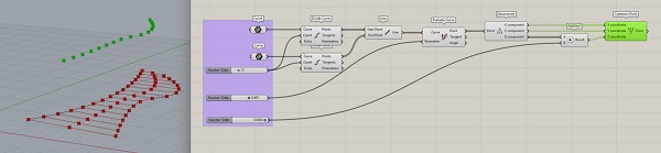
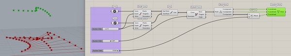
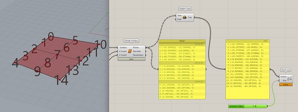
Tutorial 3 > Data Structures
Introduction to Data - Intro to Parametric Modeling
- 2 Curve components
- Divide Curve component for each
- Line component to connect the division points
- Evaluate Curve to specify a point on the connecting lines
- Straight line segments always have a Domain from 0 to 1
- Deconstruct the connecting line points into it XYZ components...to extract the Z component
- Addition component...to allow modification of the connecting line points's Z direction
- Construction Point to reconstruct the connecting line points' XYZ
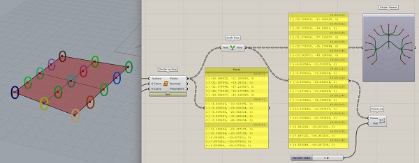
Data Structures in Grasshopper
- Surface
- Divide Surface increasing UV counts
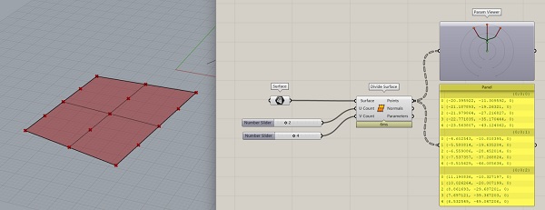
Understanding the Data Structure
Data Structures in Grasshopper - Intro to Parametric Modeling
- GH utilizes Data Trees...data organized in a tree structure
- The tree heirachy are grouped in Branches
- In this example...3 U-direction subdivisions, each containing 5 point elements
- Branches contain Paths identifier (Branch Name) to distinguish it from other branches...the 3 numbers indicating different operations, with branching occurring at the third level
- Use Parameter Viewer to look at the data tree
- The elements or Items in the branches are the data...each with an Index Number indicating its position within each branch
- A List is a collection of items inside of a branch
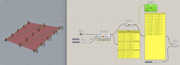
Data Tree Operations
Data Tree Operations in Grasshopper - Intro to Parametric Modeling
- Plot the Index Number of the elements using Point List
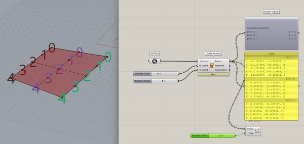
At the Tree Level, 2 operations.... - Flatten = removes all separate branch info, leaving the data in the simplest form possible...one branch only with an indexed list of elements
- Graft = make a branch for every item...opposite to Flatten...the most complex data set
In general, Grafting is better than Flattening...because recreating complexity from flattened data later is difficult. Easier to simplify later than create complexity.
List Level Behavior
List Level Behavior in Grasshopper Components
- Most GH components perform their work at the LIST LEVEL...(only a few operate at the Tree level)
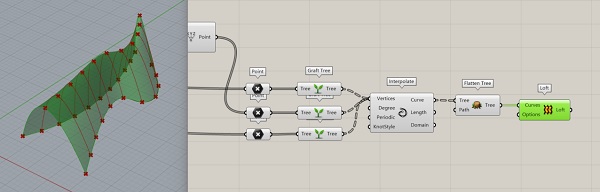
- Interpolate the raw data...get 3 lines corresponding to 3 branches
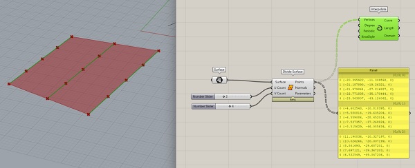
- Interpolate the Flattened data...get one line connecting all the points
CANNOT interpolate Grafted data...cannot create a curve thru only one point.
Free Form Pavillion
- The current data state of the 3 curves to make the Free Form pavillion is that they are all single branch data lists...with the same branch ID name {0,0}
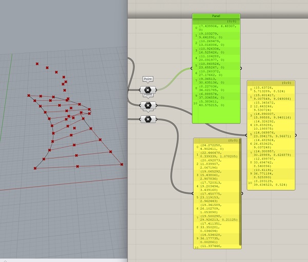
- If the output of the 3 branches are combined...they become one branch
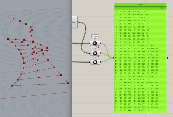
- Must restructure the data so that the sequential points on each curved are grouped
- Solution: Graft the data in each branch...before combining
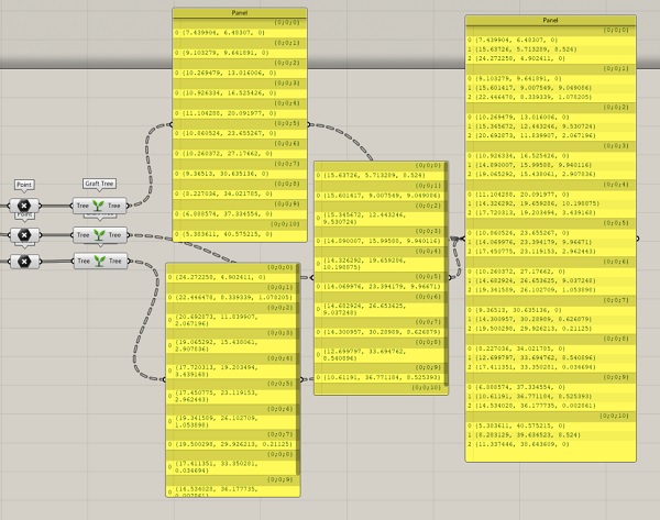
NOW the data can be correctly interpolated using...Curve/Splines/Interpolate
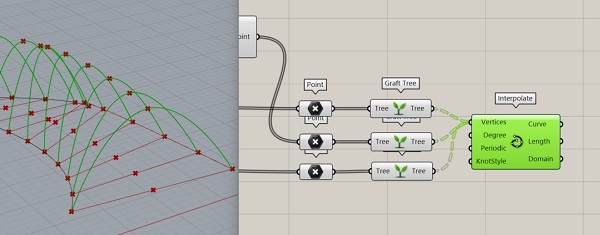
Warning: Do not go through a panel to to an output. Panels are text...and some geometries cannot be generated from text.
- Flatten the curve data to make one sequential list then apply the Surface/Freeform/Loft to create a surface connecting all the curves
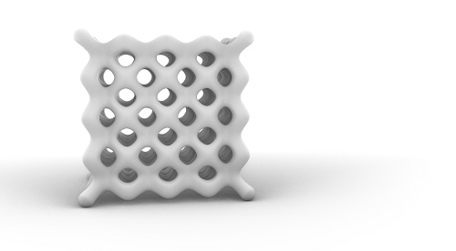
Tutorial 4 > Auxetics
- Utilizing the Linketix plugin
- Following tutorial by Rhino Grasshopper YouTube channel
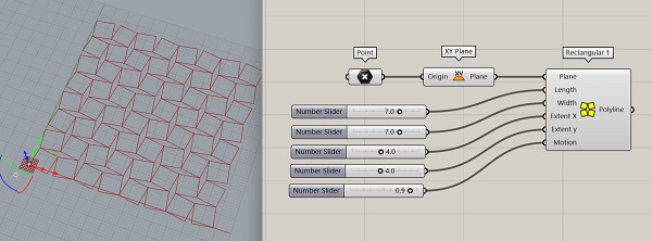
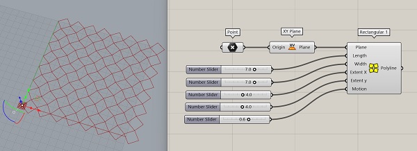
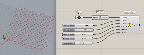
- Make a 2D auxetic surface using Rectangular 1 node component...from the Linketix plugin tab...connecting it with a Point and XY Plane components
- Use Number Sliders to adjust the Length, Width, Extent X, Extent Y, and Motion of the Rectangular 1 component
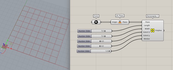
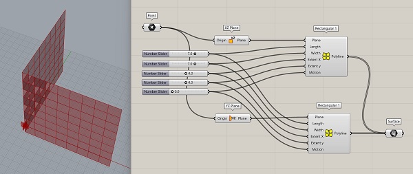
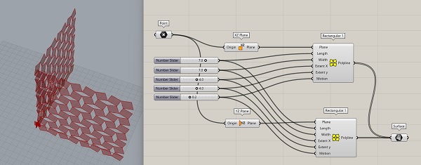
- Add extra dimensions
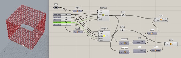
- Rt-click Bounding Box and select Union Box to achieve desired result
Tutorial 5 > Lattice Structures
3D Modeling of Lattice Structures in GH
Rather than rely on the 'Pre-made' Voronoi structure (it is so beautiful I don't want to leave it!) I wanted to learn how to make my own lattice pattern and found this video (in Italian...woo hoo!).
Step 1 > Make a Cube
- In Rhino, make a wireframe cube...exactly 1 x 1 x 1 grid module (which will be the repeating lattice module) and some lattice pattern inside of it.
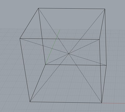
Note: I learned how to set snapping options in Rhino...bottom of the screen are options like Grip Snap and Osnap. When Osnap is selected...other options such as Point, Vertex, Mid become available.
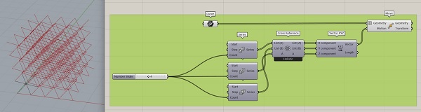
Method 1 > Vector Move
- In GH, add a Curve component...and set the interior intersecting lines of the cube as multiple curves to it.
- Add Move component
- Add Vector XYZ component
- Add 3 Series components...and connect one Number Slider component to it
= Add a Cross Reference component
- Make connections...graft the list of incoming curves to the move component...so that all curves are moved by all vectors.
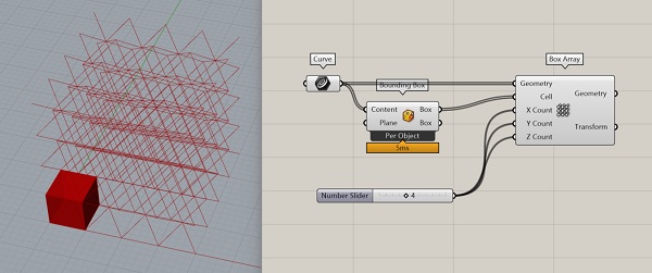
Method 2 > Box Array
- In GH, add a Curve component...and set the interior intersecting lines of the cube as multiple curves to it.
- Add a Box Array component & Number Slider for XYZ count connectors
- Add a Bounding Box component
- Done!!
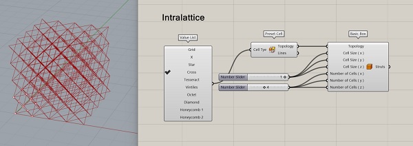
Method 3 > Intralattice Plugin
- Add the Preset Cell component...which comes with a Value List component attached
- The Value List if rt-clicked > check list contains options for different types of lattice that can be produced.
- Add a Basic Box...and connect Topologie
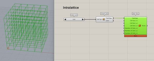
- Add Number Sliders for Basic Box inputs
- Choose Cross from Value List
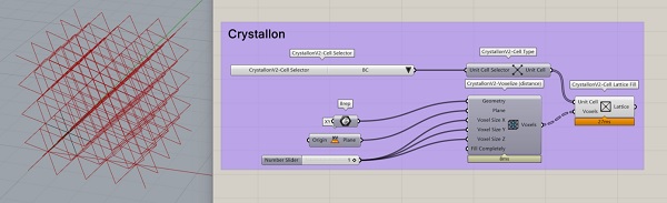
Method 4 > Crystallon
- A voxelization method
- Add Crystallon/Populate/CellSelector & Cell Type
- Add Crystallon/Voxelize/Voxelize (distance)
- In Rhino, draw a 4 x 4 box...set it to a Brep component in GH
- In GH, add an XY Plane
- Add Number Slider to give value 1 to XYZ inputs
- Fill Completely boolean input may need to be applied if the original Brep genrates issues...
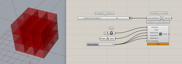
- As is...there is a problem...an extra cell in all directions...because Crystallon works on the CENTER of the cell
- So if a 4 x 4 subdivision is desired...start with a 3 x 3 cube
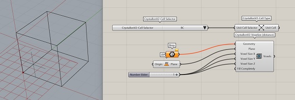
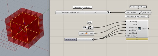
- Add Crystallon/Populate/Cell Lattice Fill...and hide building geometries
Thickening the Lattice Frame
- Thickening = generate shapes around the lattice frame 'curves'
- Which will be converted to a surface, mesh or subD...for 3D printing
Method 1 > Pipe
- Simplest, GH basic command
- Add Pipe and a Number Slider to specify radius of pipe
- Connect the Curve input to a lattice geometry...Flatten the input data
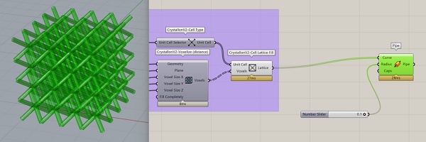
- Problem: the pipes have open ends
-
Rt-click Caps and give the pipes an end cap
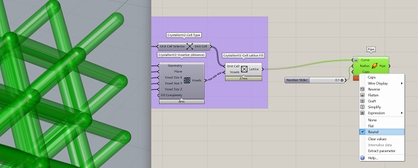
-
But the capped pipe Breps are not connected...which is a problem
- A Boolean Solid Union could be used...but it is a time consuming operation
Method 2 > Multipipe
- Add Multipipe component...and Number Sliders for its many inputs
- Multipipe generates a subD shape
- Give it Round Caps to close the pipe ends
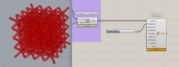
- I am not pretty close to getting an Auxetic lattice (unless this is already one??)!!
Method 2 > Intralattice Mesh
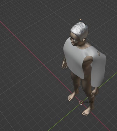
Computational Couture > Blender + Makehuman
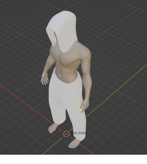
I don't have access to CLO3D. I discovered a video called [Digital Fashion in Blender]{https://www.youtube.com/watch?v=vN6z7-EChIw&t=755s} showing how Blender + Makehuman softwares can be used to generate digital couture.
Process
Makehuman.community
-
Makehuman > generate a figure...very easy to do, just move sliders to generate the figure characteristics desired.
-
My adjustments and results...
- Asian
- Male
- No Clothes
-
Makehuman > Export as .fbx file.
-
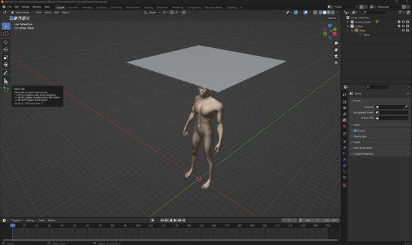
Blender > Import .fbx file. > scale to 0.1...or else the figure is huge!
-
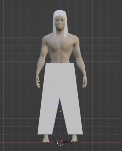
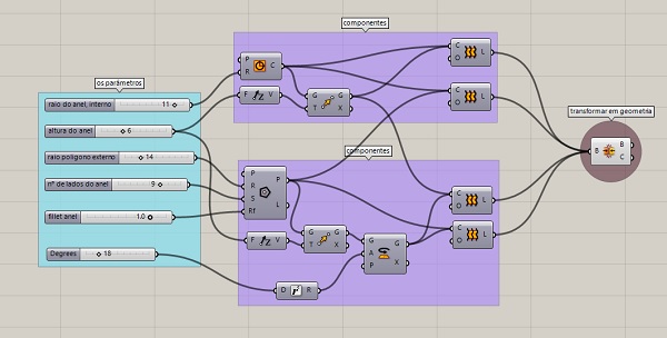
Blender > SHIFT + A to and add a MESH PLANE...which will be used to make the digital garment
-
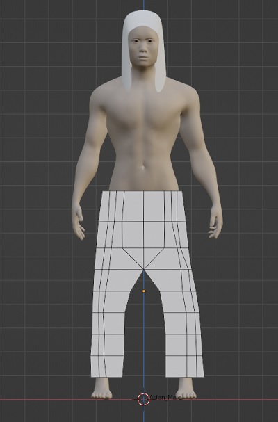
Blender > Add CLOTH and SUBDIVISION modifiers to the plane object...move SUBDIVISION modifier above the cloth modifier
-
Blender > Select SIMPLE SUBDIVISION and Levels Viewport of 4...APPLY the modifier
-
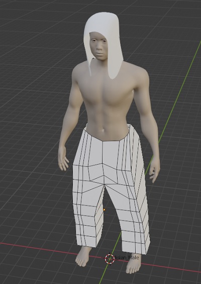
Blender > CLOTH behavior can be fine tuned in the PHYSICS tab
-
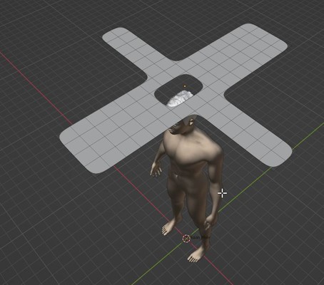
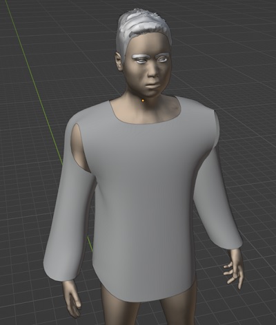
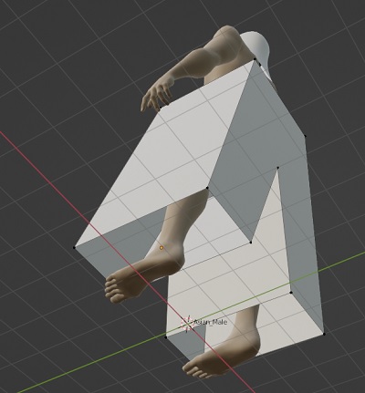
Blender > Selecting the PLANE object, click TAB to change to EDIT mode...delete subdivision squares from the plane to make a head holes, arms, front and back of the shirt (the resulting shape should look like a cross with a hole in the middle)
-
Blender > Use proportional edit (click O) to move the arms, front and back of garment down to a rough approximation of a shirt
-
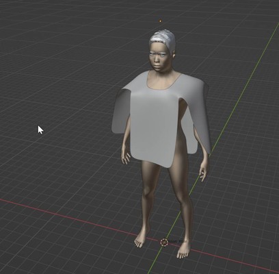
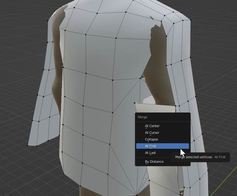
Blender > Select EDGES (hold down SHIFT to select multiple contiguous edges) and use E (extend) + X or Y direction...rough out sleeves and torso shape
-
Blender > Connect edges by Selecting vertex points (hold down SHIFT and select 2 vertices) on the edges to be 'virtually sewn' and using M (merge) to joint the vertices.
Animation > Mixamo (by Autodesk)
- Blender > select collision objects (the figure, typ.)...export as .OBJ
- Mixamo > Upload .OBJ
- Mixamo > choose motion...walking in place
- Mixamo > make slider adjustments...walking speed, arm spacing
- Mixamo > export > .FBX, 30fps, with skin, no reduction
- Blender > import .FBX file
- Blender > select armature, pose mode, select all bones, translate bone motion keyframes ahead ~20frames (click and drag in timeline...gives animation time to morph from static pose to walking cycle), reset keyframe marker to 1, pose menu > clear transform > all, with all bones selected in main display and time line at 1...I (add keyframe > location, rotation, scale)
Rigging Armature to Character Mesh > Blender
Intro to Rigging and Armature to a Character in Blender 3.0
Class Review
Elena Bannaia/Ziphouse
- Kombucha with Hibiscus for color
- Use Gelatin (plasticity) and Agar Agar
- Week Assignment: Make material and record recipes
- Color...as well as texture and plasticity
- Add vinegar or clove oil to avoid mold
- Make a standard material record sheet to make recording experiments more
Icelandic Textile Lab - alginate plastic noodles! - kombucha composite with layers of thin sheets
Shahd Farran/Jordan - gelatin, glycerin, agar agar, sodium alginate (for bio yarn) - use bubble wrap as drying base
Paula - Youyang Song > Fruit Plastic
Class Notes
 Lecturer > Aldo Sollazzo/Noumena
- Architecture background
Lecturer > Aldo Sollazzo/Noumena
- Architecture background
- Data to drive design
- Parametric Design and 3D Printing...for Wearables
- Top Down Design > Ideas imposed over decision making process. The traditional approach.
- Bottom Up Design > The process drives ideas. Ideas driven by different parameters...react to information. Not designing result...designing behavior.
The Rottlace Mask for Bjork by Neri Oxman
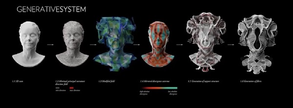
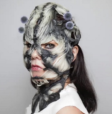
Generative process...from head model to final form
- 3D scan > point cloud > Manifold Fold > Mapped Divergent Curves > Generation of Support Structure > Generation of Fibers
- Statysys voxel based, micro level, 3D printing
Note: Generative form and pattern making...rather than deterministic human design...allows for unpredictable, organic, out-of-deterministic-control, beyond imagination results. Perlin Noise?
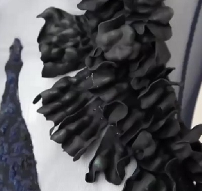
Thalassic Mask by Filippo Nassetti
Interesting extrusion of some sort of contour lines and printed with multi-colored filament.
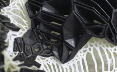
Kinematics by Nervous Systems
Tesselation technique...controlling motion by increasing or decreasing the number of tesselations in the mesh subdivision. The hinge connections looks really challenging to print and maintain. Looks rather fragile.
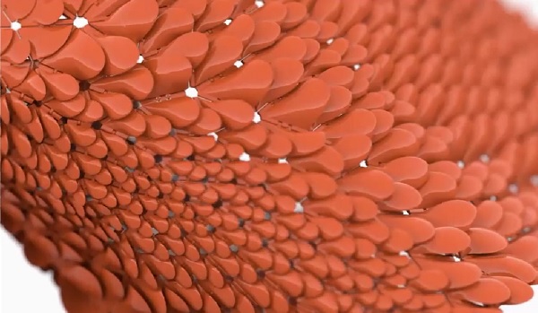
Note: A modern interpretation of chainmail. It would take a LONG time to 3D print something like this! How about flexures or living hinge cuts instead? Tesselation will certainly be a part of my Final Project
Mapping wind flow and applying geometric abstraction to generate form...
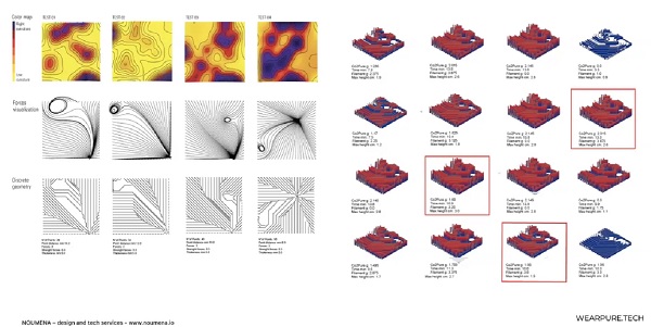
Note: This week will require some expertise with Grasshopper or Sverchok. True 3D printing.
Prosthetic Mask by Laura Civetti
Mapping a field of 3D shapes onto a 3D form, voronoi subdivision...
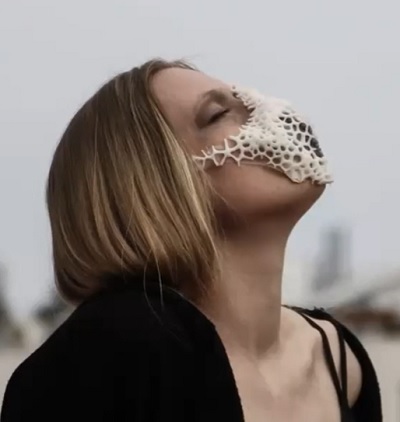
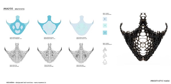
Note: A resin 3D printer best for this kind of shape. Maybe something small like a ring or earring or necklace? Does it have to be a 'fabric'?
Note: Everything is so aesthetically evocative!
Coralia 2.0 by Noumena & Cecilia Raspanti
Tesselation of 3D seaweed like form? Made with bio-materials?
True Computational Design = subjecting code to parameters and values that can be easily modified...allows variety.
- Temperature reactive textile...changes shape?
- Intential Color Deposition...work by Zeng & Deng
"Imagine designing everyday objects with impossible materials that only exist in the digital world"
Note: Hmmmmm...how to do this one? Resin pours seems the obvious choice. Pour into a computationally generated silicone mold?
Lucid by Niccolo Casas
3D Voronoi tesselation...extruded from a 2D voronoi pattern (...looks like barnacles!)
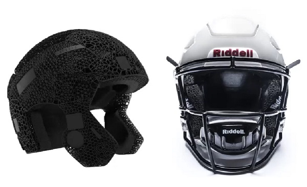
Riddell 3D Printed Football Helmet Shock Cushion
A pragmatic application. Tessalation mapping responding to greater or lessor shock forces to be absorbed. A rational aesthetic.
Note: Maybe a pair of Flip Flops with similar stress point analysis could be computationally designed? Show off Tanaka-sensei's shoe?
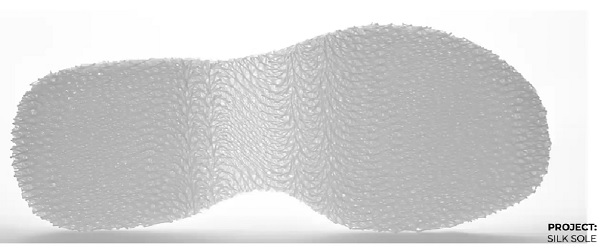
Silk Sole by Rodrigo Aguirre
Continuous printing with FDM 3D printer with flexible filament...layer by layer.
Aurora Hat by Betiana Pavon
A cap made with 3D printed modular parts.
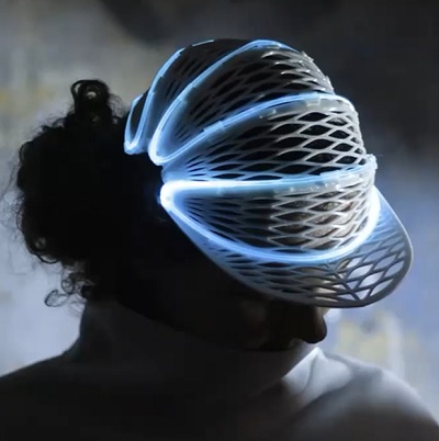
Note: Intelligent use of modular parts to reduce design time and fabrication complexity
- Add complexity in Spiral Development processes
3D Print on Textile by Ana Correa
3D printing to fuse onto fabric in a selective mannter...to control the deformation of the textile (when washed to shrink in hot water?)
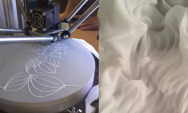
Note: I like this process! Worth exploring
Controlling how the 3D Printer Prints...to affect the textile result
Underextrusion technique over fabric to control its flexibility.
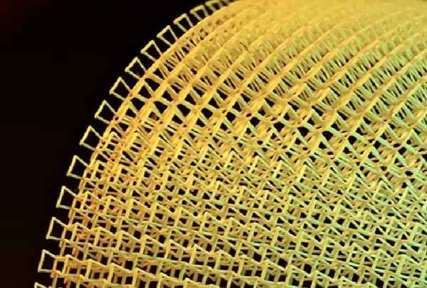
Rolled Printing to allow long 3D printed sheets on a small 3D printer. Great idea!!
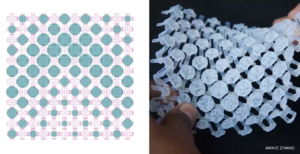
Rigid Expandable 4D Textile by Annie Zhang
3D printed, parametric design.
Piezo Electric 3D Printed Textiles by Virginia Tech
3D printing with Piezo Electric ink...to imbue the textile with special properties...chemical, electrical, thermal. The material itself acts like a sensor!!
Use a 3D pen to make sculptures But how is this computational??
Additive vs Subtractive Manufacturing
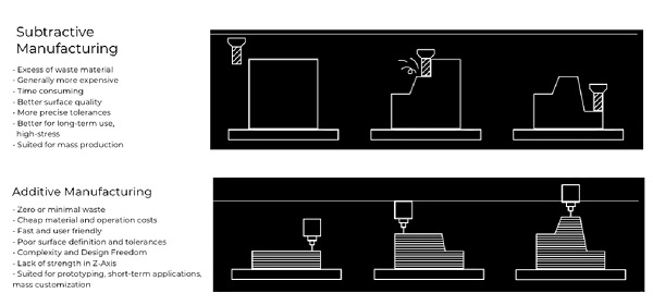
- Hack the 3D printer...to allow for unconventional printing.
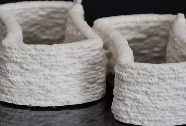
Bio Ex-Machina by Officina Corpuscoli
3D printing living material...mycellium
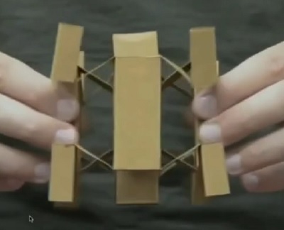
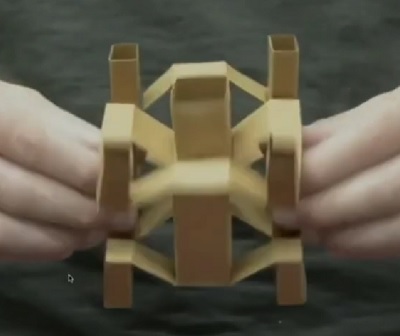
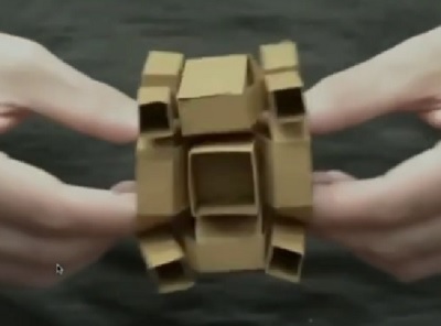
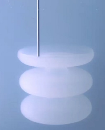
Liquid Printed Pneumatics by BMW and MIT self-assembly lab
Printing silicone with a syringe in a gelatinous pool. Brilliant idea! The syringe breaks a path in the gel to print. The gel acts as the printed pneumatic object support!
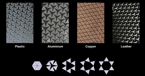
Thermorph by Morphing Matter Lab, CMU
A self-folding, origami structure. 3D printing to generate different folding properties on the surface of composite layers.
