8. Wearables
Took me a while to wrap my head around the difference between the assignment objective for this week vs the e-textiles week. After looking around at the work of others, I have come to the conclusion that...
E-textiles = understanding the options and potential of conductive fabrics and textiles that can be used to build electronic INPUT devices.
Wearables = embedding a wearable item with OUTPUT electronics.
In retrospect, I suppose that the objectives were pretty well descibed in the names...and it was me and my overwhelmed state that had trouble making sense of the distinction.
References & Inspiration
Revisiting Shih Wei Chieh again...as his work is by far the one that resonantes the most strongly with me...particularly his designs that references 'Tribal' costumes.
"I am very happy i hope you are too" by Shih Wei chieh

Assignment

My Understanding of the Objectives:
I need to create 3 swatch/sample electronic circuits total
- 2 actuator swatches designed for the body (controlled by an Attiny or Arduino)
- 1 swatch using a microcontroller (Attiny or Arduino) with one Input and one Output
- Do all of the above keeping in mind that it could be integrated into a wearable
What I will do
1. Test DF Mini Player MP3 module with Arduino
2. Test Arduino + Capacitive Touch Sensor + LED computer fan
3. Final Project: Embedded an Arduino Nano, Button and PIR sensor as a controller for an LED light array for my M1N0 final project
Assignment Work
Sound Electronics
Reverse Avalance Oscillator
I have always wanted to work on sound electronics. Aside from playing with the DF Miniplayer Module with an Arduino Uno...I actually breadboarded several Analog Oscillator circuits using just discrete electronic components.
Here is one such builds...a Reverse Avalanche Oscillator circuit using an Light Dependent Resistor (LDR) to modulate the pitch of the oscillation noise (I was moving my mobile phone backlight close to/farther away from the sensor).
I learned about using a transistor in Reverse Avalance Mode here
The circuit I breadboarded is based on this schematic...
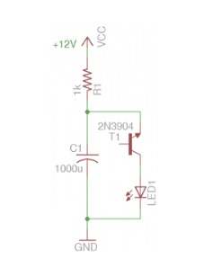
The circuit is built with the following components...
1x 2n4441 transistor (middle leg cut)
1x 1k LDR
1x 220 ohm resistor
1x 1000uF Capacitor
1x LED
1x 8ohm 4W Speaker
I can easily see that this simple circuit could be made 'soft' with conductive thread serving as wiring to connect the discrete electronics...and the speaker could be 'soft speakers' demonstrated by this week's lecturer.
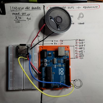
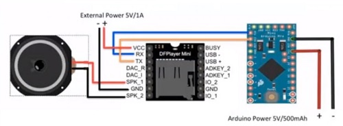
DF Mini Player MP3 Module
I followed this tutorial to learn to use the DF Miniplayer. This module is connected to an Arduino Uno as follows...
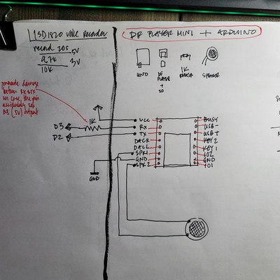
Using this code...which requires the download and installation of thhe DF Miniplayer library from here. I downloaded 3 free MP3 files from the internet and saved them to the SD card that was inserted in the DF Miniplayer.
//DF Miniplayer + Arduino
//by Fair Electro
//refactored by Rico Kanthatham, Fabricademy 2023

#include "SoftwareSerial.h"
#include "DFRobotDFPlayerMini.h" //required DF miniplayer library...download and install into Arduino IDE

#define playVolume 20
#define playTime 900

static const uint8_t TXpin = 2;
static const uint8_t RXpin = 3;

SoftwareSerial softareSerial(RXpin, TXpin); //create soft serial object and define pins

DFRobotDFPlayerMini player; //create a DF Miniplayer object

void setup() {
  Serial.begin(9600);
  softwareSerial.begin(9600);
  Keyboard.begin();

  if (player.begin(softwareSerial)) {
    Serial.println("OK");
  } else {
    Serial.prinln("Connecting to DFPlayer Mini failed!");
  }

}

void loop() {

  if(Keyboard.press("1")){
    player.volume(playVolume);
    player.play(1); //play sound files on SD card in the order it is listed
    delay(playTime);
  }

  if(Keyboard.press("2")){
    player.volume(playVolume);
    player.play(2); //play sound files on SD card in the order it is listed
    delay(playTime);
  }

  if(Keyboard.press("3")){
    player.volume(playVolume);
    player.play(3); //play sound files on SD card in the order it is listed
    delay(playTime);
  }

}
And the test went as follows...
Sandogasa
Sandogasa traditional samurai travel bamboo hat...is a simple, lightweight, handmade wearable from Japanese history.

Hack a Hat > Take Copter
When I was a kid, I used to watch a cartoon (we didn't call it Anime back then) called Doraemon. In the cartoon, the main characters were able to fly around using a magical, head-mounted propeller called Take Copter.

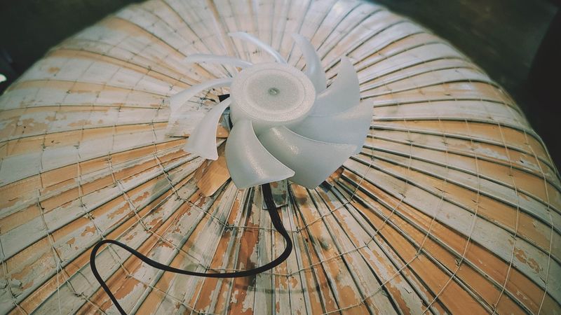
Inspired by this...I will attach a computer fan on top my the Sandogasa hat.
But before I attached the fan to the Sandogasa...I connected the LED fan to an Arduino Uno along with a capacitive touch sensor...to see if Proximity (soft) Switching of the fan could be achieved.
The circuit schematic looks like this...
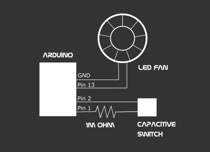
Running this code...
/*
 * CapitiveSense Library Demo Sketch
 * Paul Badger 2008
 * Uses a high value resistor e.g. 10M between send pin and receive pin
 * Resistor effects sensitivity, experiment with values, 50K - 50M. Larger resistor values yield larger sensor values.
 * Receive pin is the sensor pin - try different amounts of foil/metal on this pin
 */

 //refactored by Rico Kanthatham, Fabricademy 2023

#include <CapacitiveSensor.h>

CapacitiveSensor   touchPad1 = CapacitiveSensor(4,2);        // 10M resistor between pins 4 & 2, pin 2 is sensor pin, add a wire and or foil if desired

const int fanPin = 13;
//int fanState = 1;

void setup(){
  Serial.begin(9600);

  touchPad1.set_CS_AutocaL_Millis(0xFFFFFFFF);     // turn off autocalibrate on channel 1 - just as an example

  pinMode(fanPin, OUTPUT);
}

void loop(){
    long start = millis();
    long total1 =  touchPad1.capacitiveSensor(30);

    Serial.print(millis() - start);        // check on performance in milliseconds
    Serial.print("\t");                    // tab character for debug windown spacing
    Serial.println(total1);                  // print sensor output 1
    delay(10);                             // arbitrary delay to limit data to serial port

    if (total1 > 500){
      digitalWrite(fanPin, HIGH);
    } else {
      digitalWrite(fanPin, LOW);
    }

}
And the test went like this...
But for the initial install on the Sandogasa...I opted not to have a microcontroller and fancy capacitive switching...opting for a simpler circuit.
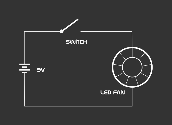
It runs on 5V-6V...the fan spins and the fan RGB LEDs changes colors. Visibility and motion has been achieved.
Placement centered on top...
Location marked and reinforced for hole drilling...

Drilling...

Power wires routed through and hole hot glued to prevent water penetration

The fan is hot glued to the top of the sandogasa to fix it in place (is there a more elegant way to attach it?)

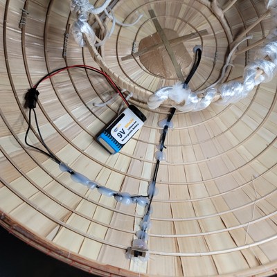
And similarly on the inside...where a switch and battery connection was soldered onto the fan wires.
M1N0 Electronics
LEDs for the M1NO
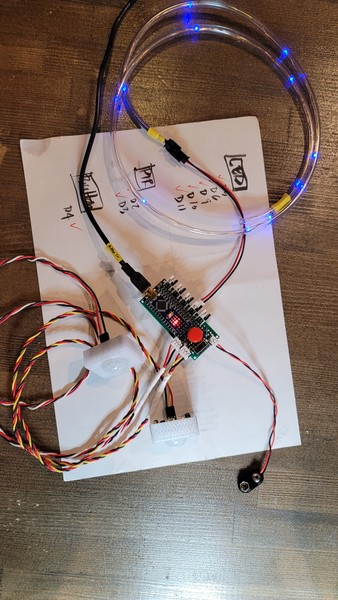
The intention is to integrate an array of LEDs (repurposed Xmas lights) behind the M1N0's rope arrays...primarily to enhance wearer visibility. The LED array will be powered by a rechargeable 5V battery...and have a control panel that will allow the array to be turned ON/OFF...as well as switch between different illumination patterns. The control panel that was part of the Xmas lights will be reused, but maybe replaced by a microcontroller...to provide additional functionality and custom control.
I took apart the non-functioning Xmas light string to diagnose its issues.
The control panel electronics looks to be in good shape, undamaged by water. The system is comprised of 2 Push Buttons, an ANA6501 power management IC, a 1.5V rechargeable NIMH battery and a Solar Panel.
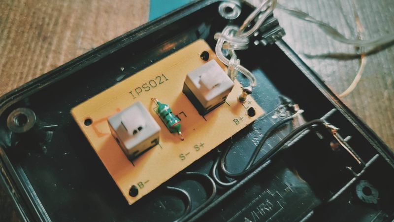
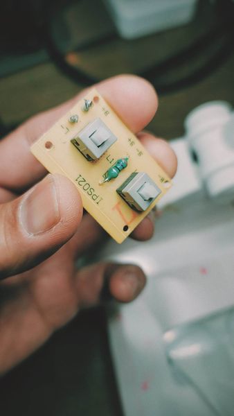
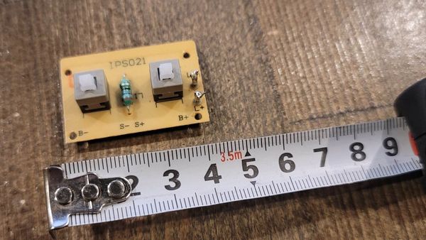
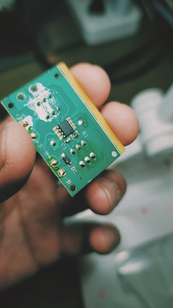
The light string wires, however, are broken in various locations along its length. Cutting the length of wire into manageable segments and connecting the sections to a power supply thankfully showed that the LEDs are in good working order (yay!).
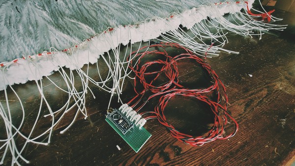
Placed behind a rope module array...the light looks very nice.
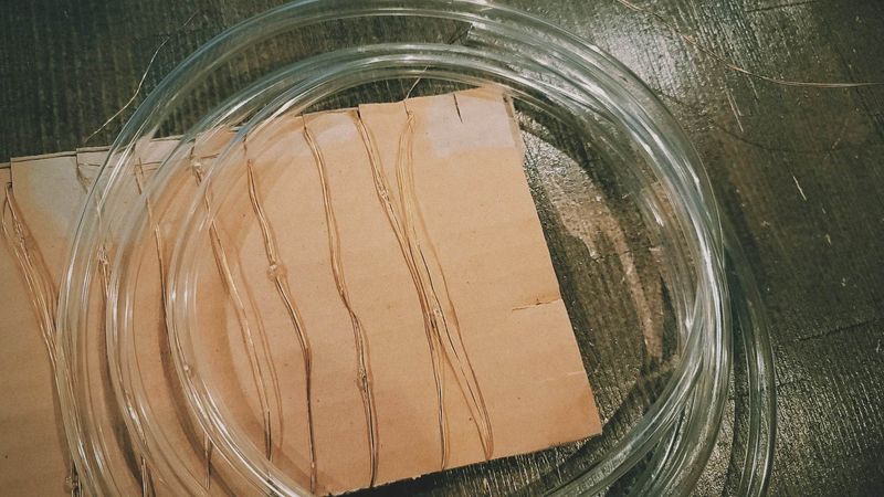
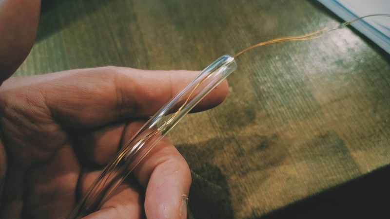
To protect the LED string from future damage, I thought to insert the LED string into protective PVC tubing.
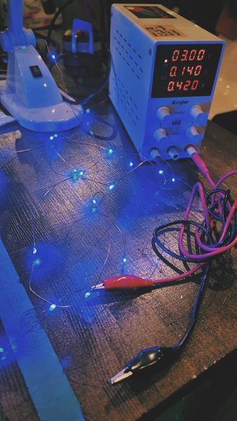
Instead of simply powering the LED string, I thought to connect it to an Arduino to see if I can take control of the light emission utilizing Pulse Width Modulation. The first attempt is to make the LEDs gently Fade In and Out.
Connecting the Negative lead of the LED string to the Arduino Uno's GND pin and Positive lead to PWM pin 9. I soldered a 220 ohm resistor to the end of Negative wire to help make sure the current is low enough not to blow out the LEDs.
I wrote and uploaded the following code...
//Fading an LED String
//by Rico Kanthatham, Fabricademy 2023

int LEDstring = 9;
int brightness = 5;
int fadeRate = 10;


void setup() {
  pinMode(LEDstring, OUTPUT);
}

void loop() {
  analogWrite(LEDstring, brightness);
  brightness+=fadeRate;

  if (brightness == 5 || brightness == 255) {
    fadeRate = -fadeRate;
  }

  delay(250);
}
The light, thankfully, behaved as expected.
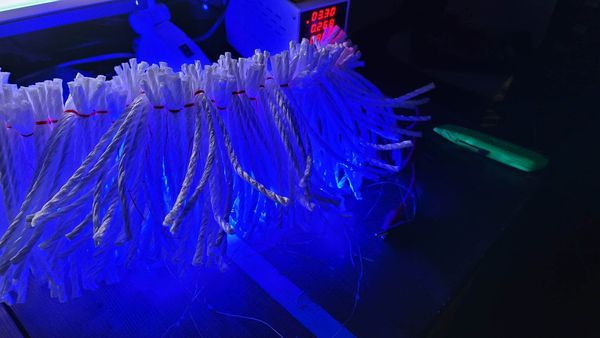
Now time to test the light behind the Rope Array Outer Shell.
The videos exaggerated the brightness of the LEDs...but the real life effect was subtle and pleasing. Rather than each LED generating a point light, a general glow bled through the translucent PE rope. I count this initial test as a success.
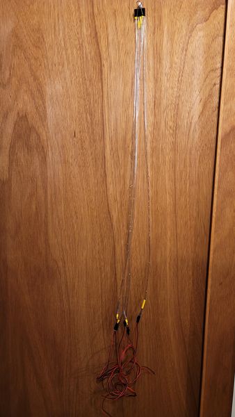
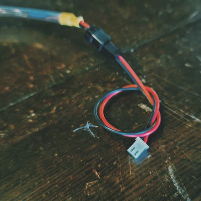
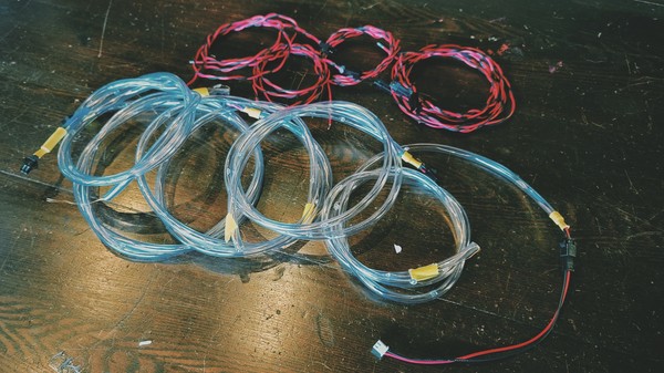
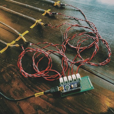
Building the M1N0 LED Wire Harness
Connectors
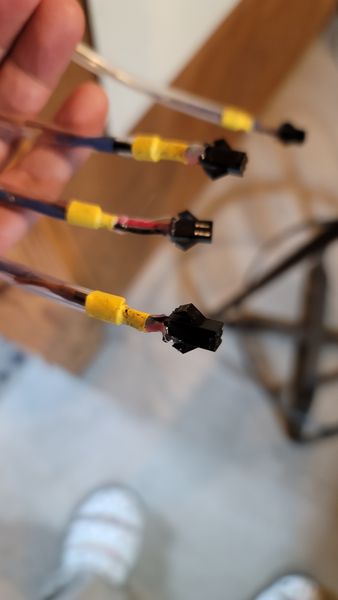
Soldered to LED Strands
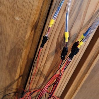
5 Strands Completed
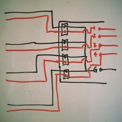
Building The M1N0 Light Array Control Board
Control Board - Design Schematic
Control Board - Building
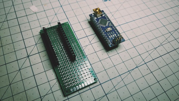
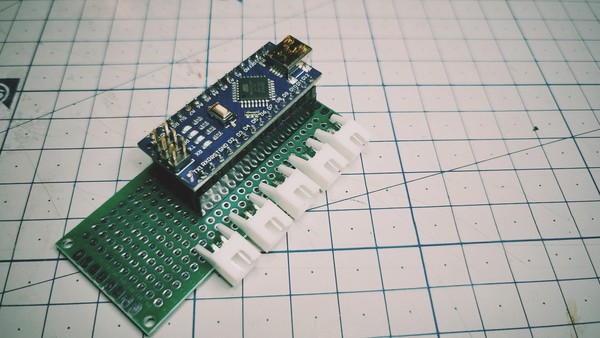
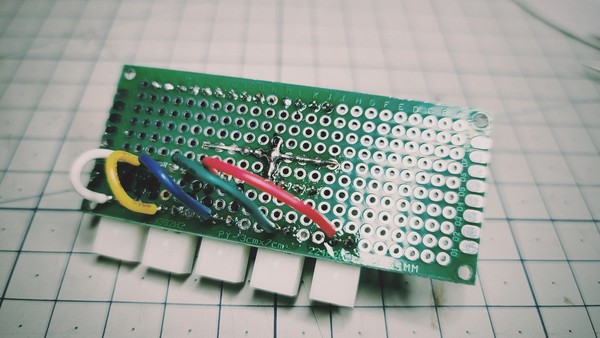
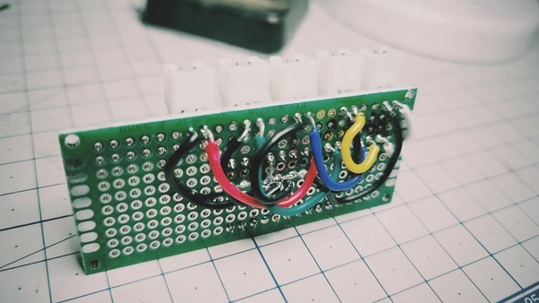
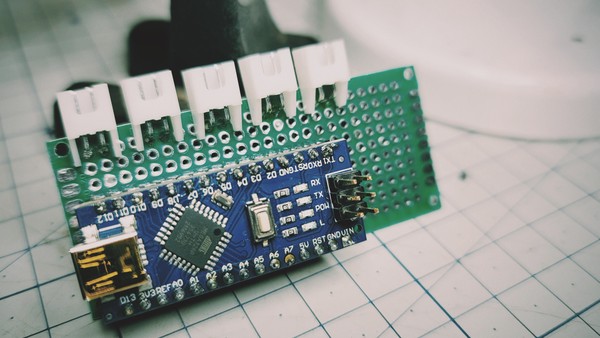
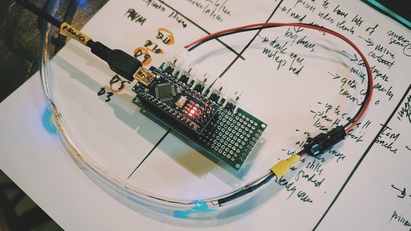
LED Array - Wiring & Installing


Testing the Control Board + LED Array
Additional code adds more light patterns than just fading...
//M1N0 LED String
//by Rico Kanthatham, Fabricademy 2023

int LEDstrings[] = {6, 9, 10, 11};
int brightness = 5;
int fadeRate = 10;
int flashDelay = 800;
int size;


void setup() {
  Serial.begin(9600);

  size = sizeof(LEDstrings) / sizeof(int);

  for (int i = 0; i < size; i++) {
    pinMode(LEDstrings[i], OUTPUT);
  }

}

void loop() {

  for (int i = 0; i < size; i++){
      slowFade(i);
   delay(80); //breath = 60, warning = 5, panic = 1
 }

  //  delay(1000);

  for (int i = 0; i < size; i++){
    flash(i);
  }
}

void slowFade(int s) {
  analogWrite(LEDstrings[s], brightness);
  brightness += fadeRate;

  if (brightness == 5 || brightness == 255) {
    fadeRate = -fadeRate;
  }
}

void flash(int n) {

digitalWrite(LEDstrings[n], HIGH);
delay(flashDelay);
digitalWrite(LEDstrings[n], LOW);
delay(10);
}
Sensing for the M1N0
PIR Sensor
I learned how to use the PIR Motion Sensor from reading this excellent description at Adafruit and also from this YouTube video by How to Mechatronics.
Some key learnings:
- PIR = Passive Infra-Red
- The PIR is a Pyro Electric (Infrared radiation) sensor

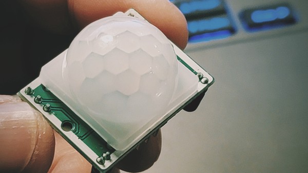
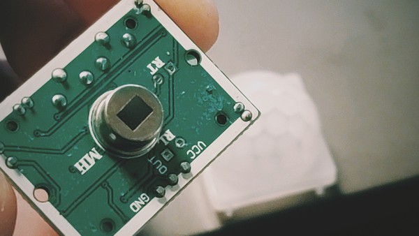
- The PIR module has 3 connection pins...VCC, Signal and GND
- The PIR module has a movable jumper connector that allows it to switch functionality from Repeatable Trigger (H position) to Non-Repeatable Trigger (L position)


- Repeating Trigger mode...continues to reset the starting time as long as movement is detected by the sensor
- Non-Repeating trigger mode...automatically reverts back to LOW state after the specified HIGH state duration has been reached, i.e. does not trigger or reset the starting time once it is initially triggered
- The PIR module also has 2 adjustable trim potentiometers...to adjust detection distance sensitivity (up to 7m) and triggered state duration (0.3s to 5mins)

- The PIR module requires some warm up time
- The PIR module's white dome cover is actually a fresnel lens that widens the view angle of the sensor (expands the visible detection area)
PIR Settigs Decisions:
- Retriggering mode
- 2m to 3m detection range
- 5s triggered duration
I want to use PIR sensor(s) to detect approaching people...to trigger an 'excited' light pattern in the M1N0. The sensors will likely be installed in the 'collar' area of the...one pointed towards the back and one pointed to the front.
Code used to test the PIR sensor
*```
 * PIR sensor tester
 */

int ledPin = 13;                // choose the pin for the LED
int inputPin = 2;               // choose the input pin (for PIR sensor)
int pirState = LOW;             // we start, assuming no motion detected
int val = 0;                    // variable for reading the pin status

void setup() {
  pinMode(ledPin, OUTPUT);      // declare LED as output
  pinMode(inputPin, INPUT);     // declare sensor as input

  Serial.begin(9600);
}

void loop(){
  val = digitalRead(inputPin);  // read input value
  if (val == HIGH) {            // check if the input is HIGH
    digitalWrite(ledPin, HIGH);  // turn LED ON
    if (pirState == LOW) {
      // we have just turned on
      Serial.println("Motion detected!");
      // We only want to print on the output change, not state
      pirState = HIGH;
    }
  } else {
    digitalWrite(ledPin, LOW); // turn LED OFF
    if (pirState == HIGH){
      // we have just turned of
      Serial.println("Motion ended!");
      // We only want to print on the output change, not state
      pirState = LOW;
    }
  }
}
Button Actuation
The final controller has a button that can be used to activate a high rate flashing of the LED array from the normal 'Slow Flow' light pattern. A tact-switch button was soldered to the perforated PCB board and wired to the Arduino.
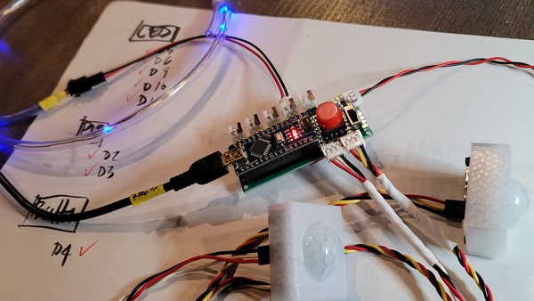
The additional code to allow button function and PIR function is here...
//M1N0 Final Project Control Program
//by Rico Kanthatham, Fabricademy 2023
//License: Creative Commons Non-Commercial Attribution

//Debug LED
const int ledPin = 13;

//LED String
const int LEDstrings[] = {5, 6, 9, 10, 11};
int brightness = 5;
int fadeRate = 1;
int delayShort = 100;
int delayLong = 100;
int size;

//PIR Sensor
const int inputPin1 = 2;               // input pin PIR sensor 1
const int inputPin2 = 3;               // input pin PIR sensor 2
int pirState1 = LOW;             // initial PIR1 state...no motion detected
int pirState2 = LOW;             // initial PIR2 state...no motion detected
int val1 = 0;                    // PIR1 read value
int val2 = 0;                    // PIR2 read value

//Button
const int buttonPin = 4;     // pushbutton pin number
int buttonState = 0;         // initial pushbutton state

void setup() {
  Serial.begin(9600);

  pinMode(ledPin, OUTPUT);
  pinMode(inputPin1, INPUT);
  pinMode(inputPin2, INPUT);
  pinMode(buttonPin, INPUT);

  size = sizeof(LEDstrings) / sizeof(int); //determine the size of the LED Strings Array

  for (int i = 0; i < size; i++) {
    pinMode(LEDstrings[i], OUTPUT);
  }
}

void loop() {

  //Status Quo expression of LED String Array
  for (int i = 0; i < size; i++) {
    slowFade(i);
  }

  //Check PIR sensor for detected motion
  sensor1();
  sensor2();

  //Check Button for press
  button();
}

//Slow Fade LED pattern
void slowFade(int s) {
  analogWrite(LEDstrings[s], brightness);
  brightness += fadeRate;

  if (brightness <= 5 || brightness >= 255) {
    fadeRate = -fadeRate;
  }
  delay(delayLong);
}

//Flash LED Pattern
void flash(int n) {
  digitalWrite(LEDstrings[n], HIGH);
  delay(50);
  digitalWrite(LEDstrings[n], LOW);
  delay(20);
}

//PIR sensor 1
void sensor1() {
  val1 = digitalRead(inputPin1);  // read input value
  if (val1 == HIGH) {            // check if the input is HIGH
    digitalWrite(ledPin, HIGH);  // turn LED ON
    for (int i = 0; i < size; i++) {
      flash(i);
    }
    if (pirState1 == LOW) {
      // we have just turned on
      Serial.println("Motion detected PIR1!");
      // We only want to print on the output change, not state
      pirState1 = HIGH;
    }
  } else {
    digitalWrite(ledPin, LOW); // turn LED OFF
    if (pirState1 == HIGH) {
      // we have just turned of
      Serial.println("Motion ended PIR1!");
      // We only want to print on the output change, not state
      pirState1 = LOW;
    }
  }
}

//PIR sensor 2
void sensor2() {
  val2 = digitalRead(inputPin2);  // read input value
  if (val2 == HIGH) {            // check if the input is HIGH
    digitalWrite(ledPin, HIGH);  // turn LED ON
    for (int i = 0; i < size; i++) {
      flash(i);
    }
    if (pirState2 == LOW) {
      // we have just turned on
      Serial.println("Motion detected PIR2!");
      // We only want to print on the output change, not state
      pirState2 = HIGH;
    }
  } else {
    digitalWrite(ledPin, LOW); // turn LED OFF
    if (pirState2 == HIGH) {
      // we have just turned of
      Serial.println("Motion ended PIR2!");
      // We only want to print on the output change, not state
      pirState2 = LOW;
    }
  }
}

//Button Action
void button() {
  // read the state of the pushbutton value:
  buttonState = digitalRead(buttonPin);

  // check if the pushbutton is pressed. If it is, the buttonState is HIGH:
  if (buttonState == HIGH) {
    // turn LED on:
    digitalWrite(ledPin, HIGH);
    for (int i = 0; i < size; i++) {
      flash(i);
    }
  } else {
    // turn LED off:
    digitalWrite(ledPin, LOW);
  }
}
Class Notes
Review
Silvia Lugo/Fablab Cidi
- Parakeet plugin...generates kaliadoscope patterns
- ShapeDiver online sharing of GH
Ala Janbek/Techworks
- Circassian
- Clothing & Culture
- Circassian motif
- Printing on fabric...stretch and clip the fabric onto the build plate, reduce speed
Lisa Boulton
- Clay habitat for wildlife!
- Anastasia suggests...print patterns flat...then use heat gun to 'bend' the shape over the form
Camille Barot
- 3D printed lace panels
- Spirograph in GH
- Fabrics for 3D printing: Organza, Muslin, Tencel, Tulle, Lycra
Anastasia: FP can be research into the limitation and range of fabric deformation from 3D printed control patterns
Wearables Lecture by Liza Stark
- last time...mostly Inputs (sensors, data collectors)
- this time...about Outputs
-
Acuators & Attiny
-
Wearables...to express identity, communication, protection
- Wearable...as Second Skin
Wearable
I like this statement..."The project is system...a constant dialogue between the hardware and the material". It raises a bunch of questions in my mind...
- How to make the end result not Electronics biased or Textile biased?
- How to create a project where both aspects are equally important to the end result?
- "How to design electronics meant to be worn on the body?"
- Whether the electronics should be hidden or displayed on the wearable?
A Wearable will engage the body, will be a Second Skin and will serve some sort of purpose for the body. Because the Wearable will come into contact with the body...issues of comfort and tactility arising from the Material chosen must be considered.
The Electronics will enhance the Wearable...providing the Wearable with additional, 'intelligent' functionality or features. I beleive that it is important that it does not disrupt the comfort and tactility aspect of the Wearable that is associated with the Material.
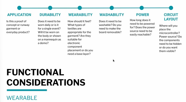
As a Wearable...there are practical realities that must also be considered in addition to comfort and tactility...Durability, Wearability, Washability, etc. must be thought through.

An important slide...to think about how intrusive the Wearable should be to the public consciousness. Is the Wearable a private device whose functionality is invisible to others...or is it one that is meant to engage public consciousness.
Note: ESP32 as base to allow for wifi functionality? Note: Would be funny to go to Starbucks and plug in your clothes
Actuator
- Acutator = Output
- Visual, Sound, or Motion...output
- Examples...LED, Motors, Speakers, Thermochromic Ink
Visual
LEDs...Light Emitting Diodes...don't forget the 220 ohm resistor
Kathleen McDermott > Measuring Subway Noise Levels

I love the cheeky humor, aesthetics and safety orange color of this project! Doing more than just turning on a bunch of (potentially irritating) LEDs.
Note: Electronics enhanced Wearable...reacts to what in the environment and for what purpose...other than simple visibility and attention seeking?
NeoPixel...programmable RGB LEDs...only one signal pin required.
- Power hungry...requires a lot of current (60mA each for Full Brightness...40mA may be OK)...a bigger battery or wall plug would be a good idea for long ON time.
- 470 ohm resistor recommended between microcontroller signal pin and Neopixel signal pad
- 1000 uF Capacitor recommended across VCC and GND power lines connected to the Neopixel power pads...to keep current stable.
- Neopixel Code Generator by Adriano Tiger. This is super useful!!
Fiber Optics
- Light source at one end...transmits light to the other end > End Emitting...or makes the fiber optics cable glow > Side Emiiting
- High watt LED or LED with narrow viewing angle...best
- The quality of the fiber determines the degradation of light over distance
- "The tricky part is to attach the LED to the fibers in a way that directs light directly into the fibers"
- Fibers are heat sensitive...will melt if too much heat is nearby
- Hot glue (melt fibers) and crazy glue (disintegrate fibers) not good options
- Use E6000 adhesive
- But with Xacto knife
Artificial Intelligence and Its False Lies by Mika Satomi

Note: EL wire as alternative?
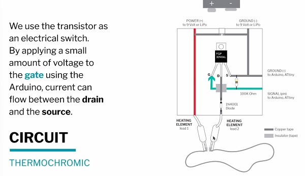
Thermochromic Ink
- "Pigments that change state in the presence of heat"...become colorless
- Heat wire under the fabric...to generate patterns
- Thin fabric and lots of pigment = faster results
- Silkscreen the pigment onto the fabric...for ideal for uniformity
- Heating element (wire)...Stainless Steel conductive thread, Karl Grimm conductive thread, Nichrome wire, flexenol(?)
- Minimum 2.5 ohms of resistance
- 5V power ideal...generates about 770 mA of current thru 6.5 ohm of resistance
- Arduino pin can only output 40mA which is not enough for heating
- if 6.5 ohms and 500 mA to 1000 mA of current desired...use a 9V battery + 400 ohm resistor
- Copper tape is NOT a good option
- 33C to cause effect
- Use a MOSFET (FQP30N06L) to provide enough current to the heating element...act as a switch
Note: This is like invisible ink in reverse!
Note: Use Thermochromic Ink...and 7 segment display?
Wifi Tapestry by Richard Vijgen

Sound
Note: I definitely want to do this this week!
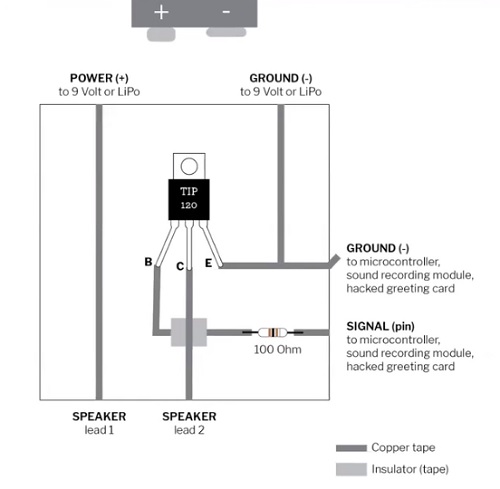
- Speakers require a Class D Audio Amplifier
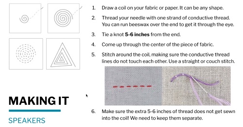
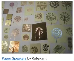
- Components: Silver Thread + Neodynium Magnets + 2.5W speaker + Class D Amp
- The spiral patterned thread generates sound...is an electromagnetic field that reacts agains the Neodynium (permanent) magnet stack...vibrations the result of electrical current that turn ON/OFF
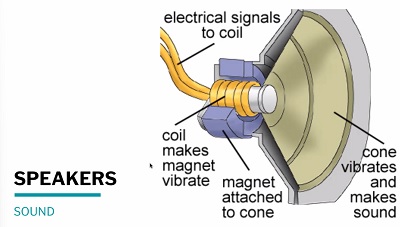
- Tighter coil = stronger magnetic field, louder sound
- Stiff and Thick = louder sound
- Larger magnet = louder sound
- Magnet at Coil Center = louder sound
- Material: Copper tape, copper wire, silver wire
- Process: Vinyl cutting, weaving, sewing


-
DFplayer mini...playback only
-
Teensy audio shield...can do synthesis...more control and more audio power
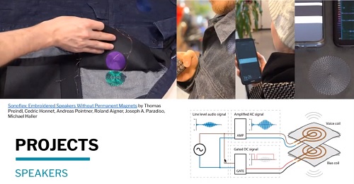
- A second coil can be used in place of a permanent magnet as demonstrated by Sonoflex: Embroidered Speakers without Permanent Magnets" by an MIT group
Note: Is it possible to make sort of a Eurorack with alligator clips and various clip-points on a textile piece?
Shape Memory Alloy
- Flexinol, changes shape when heated...'trained' vs 'untrained' type...'trained' easier
- "Don't use with polyester (will melt)"
- "Lightweight paper or fabric...yields the best results"
- The greater the wire diameter...the more power required
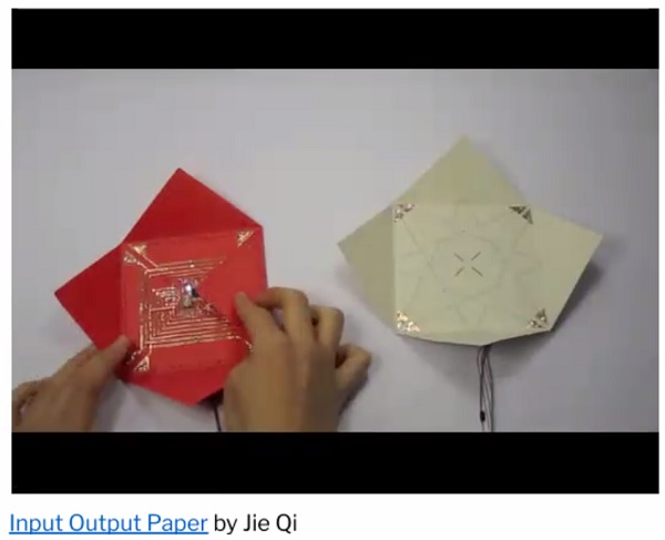
Jie Qi > Auto-Folding Paper
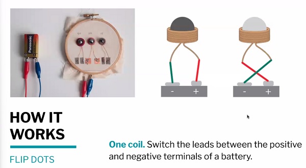
Flip Dots
- Hemetite Bead...magnetic, flips with current when run thru 2 stacked coils (ea with different polarity)...hook up to H-bridge circuit
- Bigger magnet...more EMF needed
- At least 50 coils...30AWG recommended
Haptic Motors
Note: Vibration motors to make hat wings?
- Require motor driver if control and precise behavior required
Monarch by Social Body Lab

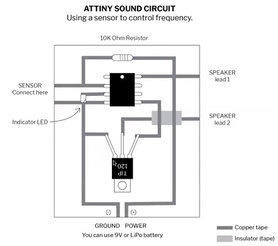
Attiny
Attiny 45/85
- small form factor
Attiny 45 Pin Out
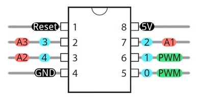
Attiny 44/84
- Can be programmed via Arduino Uno
- Software Serial (no hardware TX/RX pins) required to access the Serial Monitor
- Sample circuits: Touch, Variable Resist, Switch
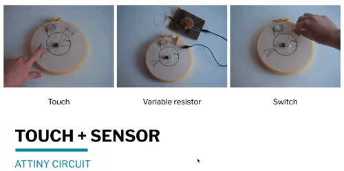
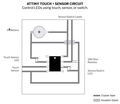
Touch Circuit
Sound Circuit
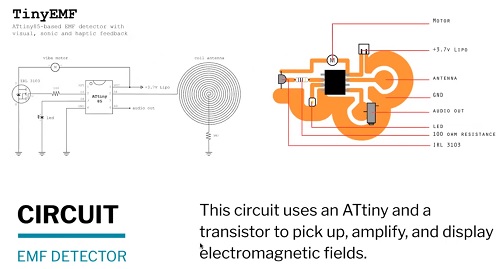
Tiny EMF Detector Circuit (for glove?)