04 electronics
Electronics
Initial Brainstorming:
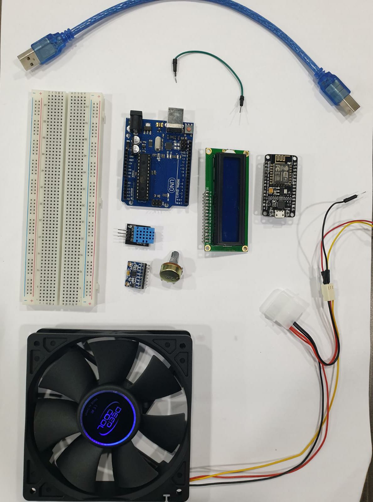
As a start, I gathered the electronic parts i needed to use to build the incubator such as: Fan, temperature & humidity sensors, wires, Arduino UNO microcontroller, Heating element, Wifi ESP 32 module, Relay, LCD display and Power supply.
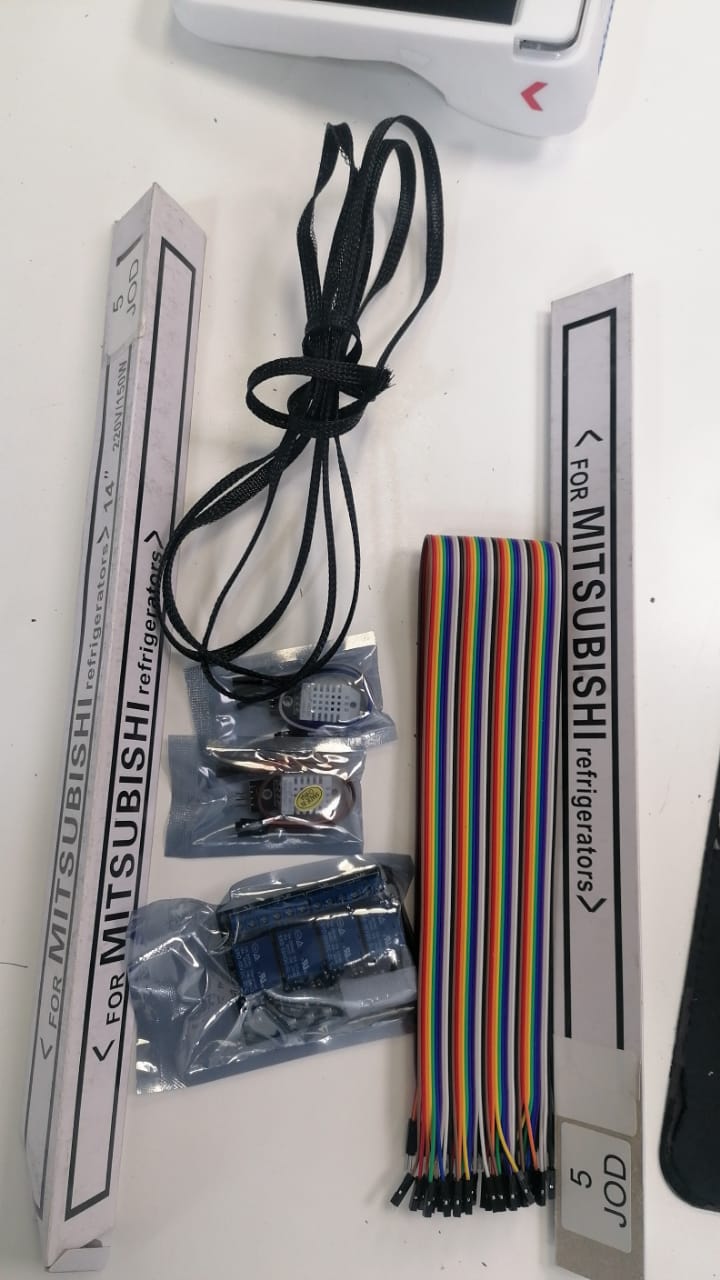
- Components from local store in Amman:
Testing Components
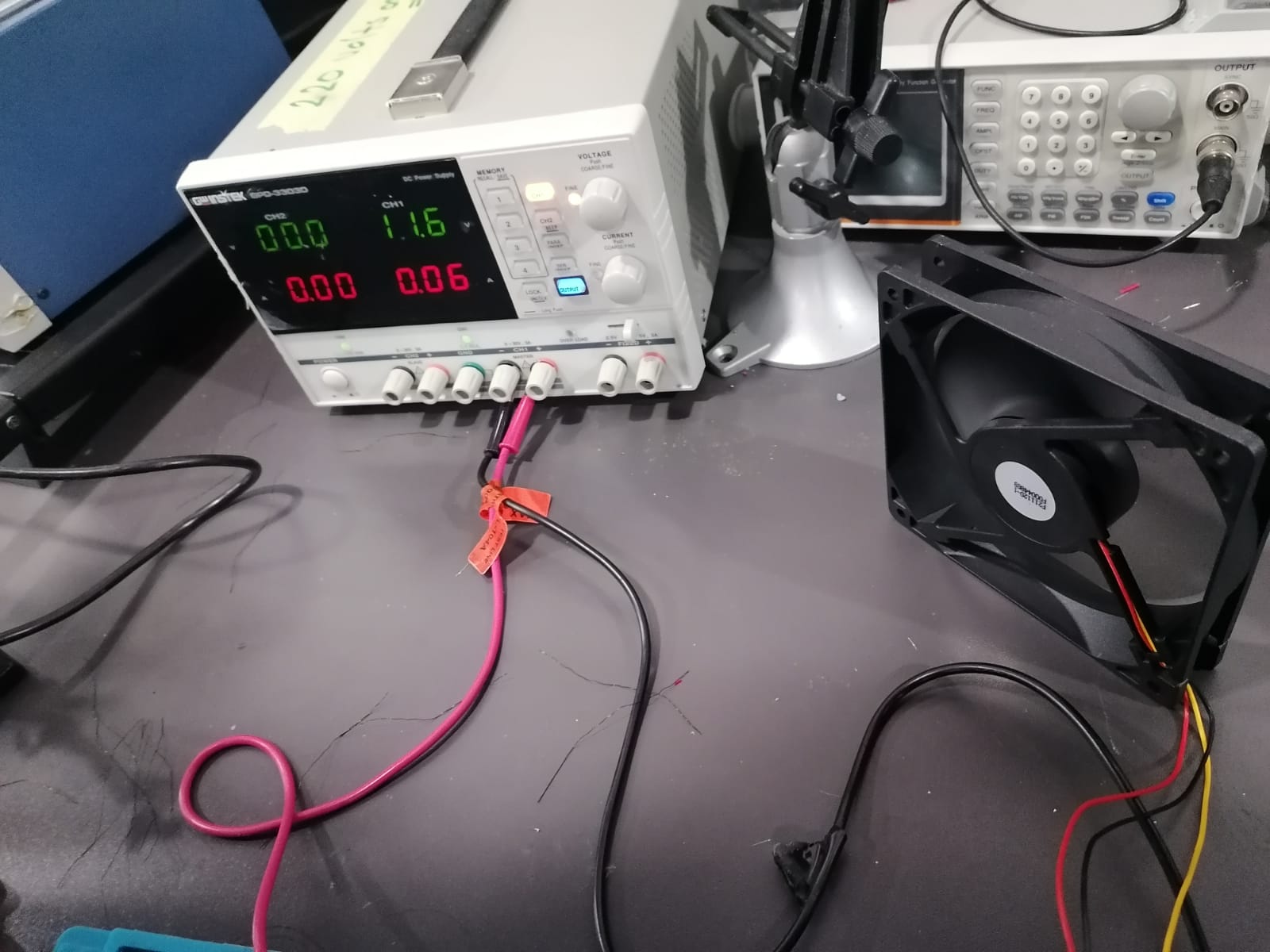
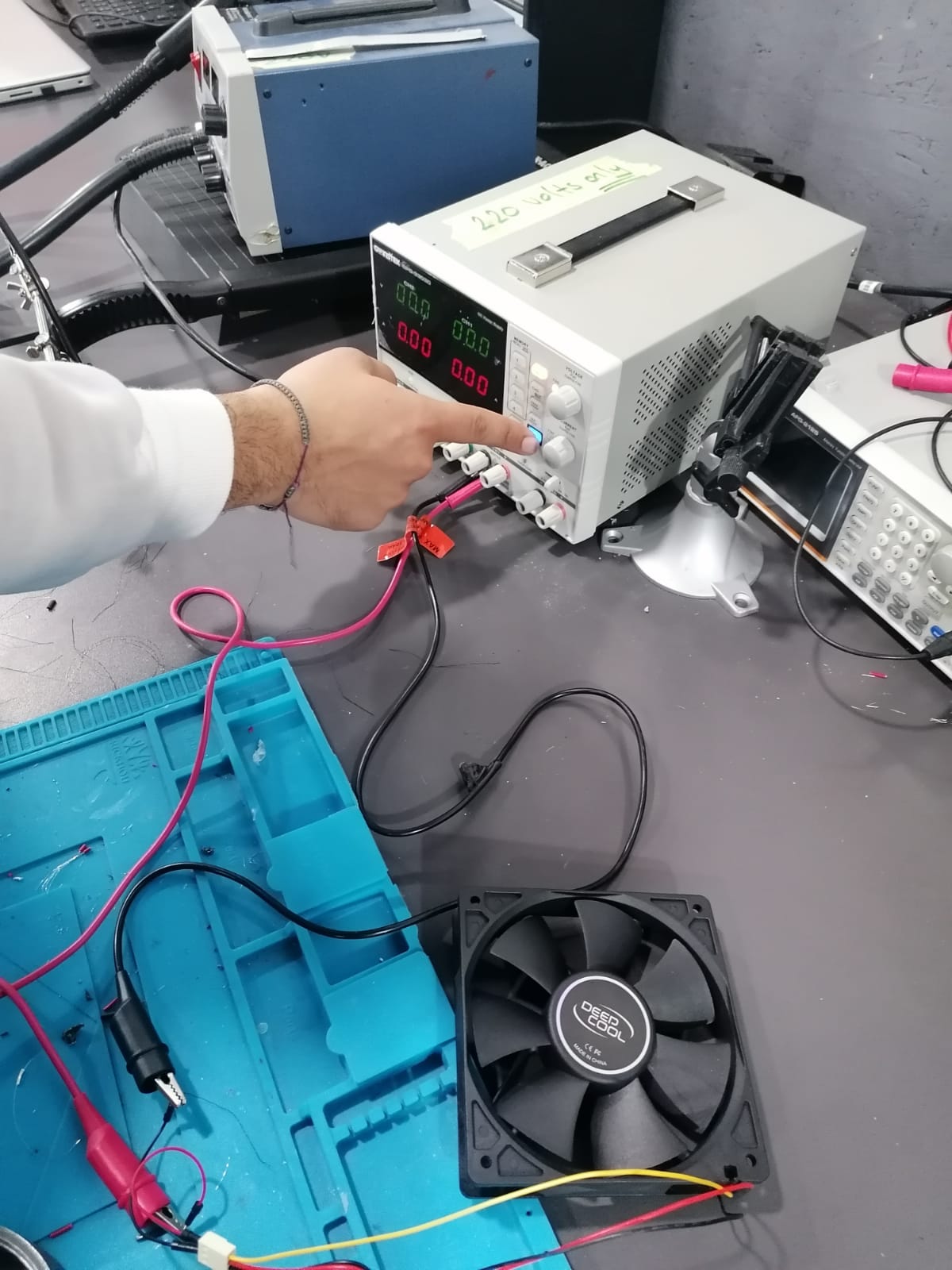
Testing 12V Fan:
I tested the fan by connecting the ground and VCC with power supply and check the fan is working fine.
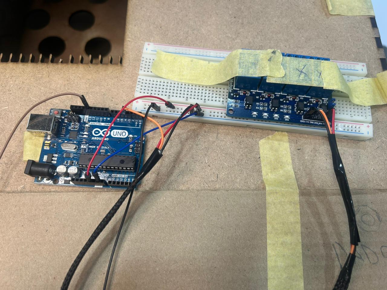
Later on I connected it to the Arduino using the following schematic.
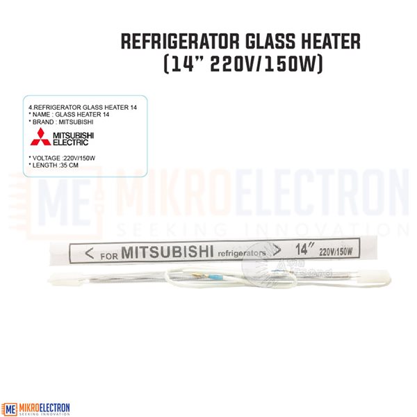
Testing HEATER
I bought the heater with the following specification, usually used in the common refrigerators:
- 150Watt - output: 220Volts
Later on I connected to the Arduino to test it in combination with the Humidity Sensor.
Tesing the Temperature & Humidity Sensor :
I bought the temperature and humidity sensor to detect the right temperature needed for my incubator.
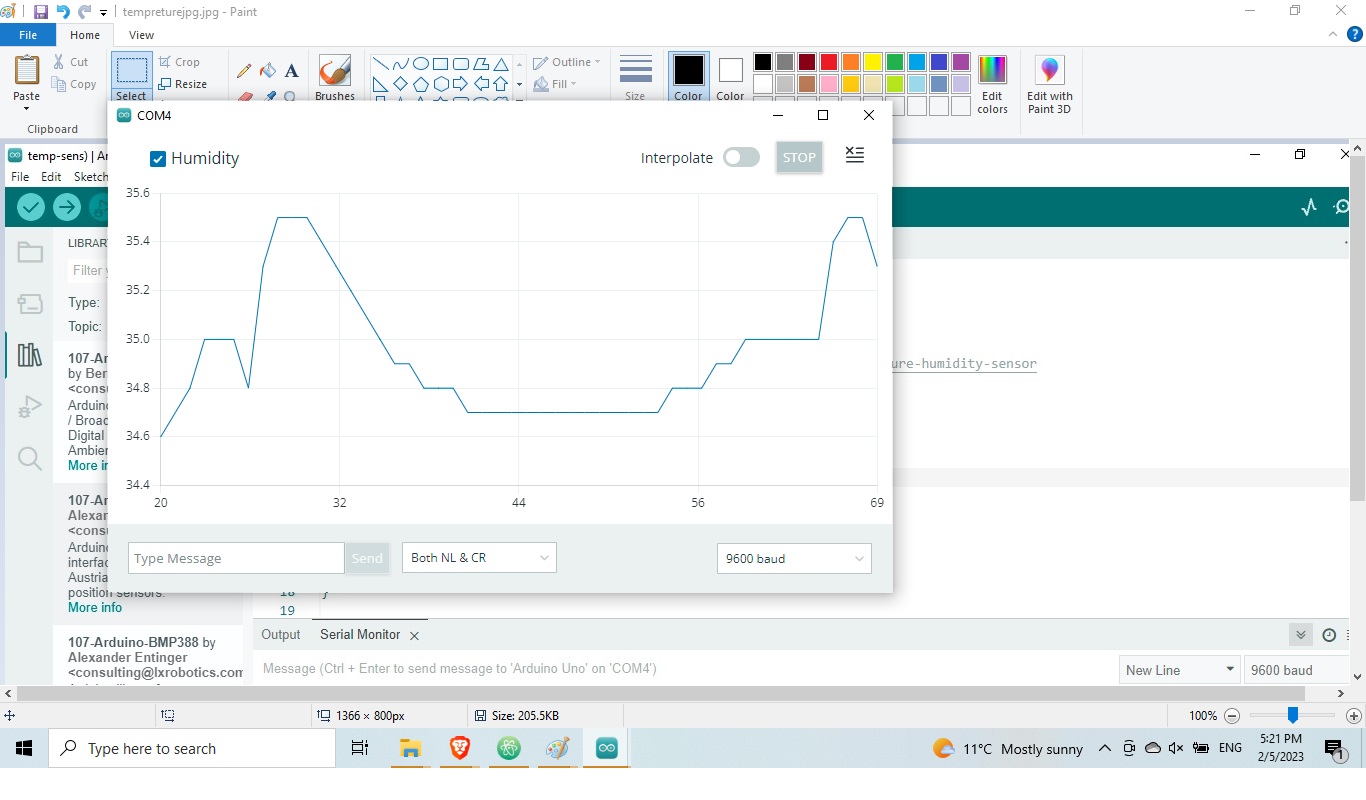
from the picture above we can trace the the diffrent in humidity level inside the incubator.
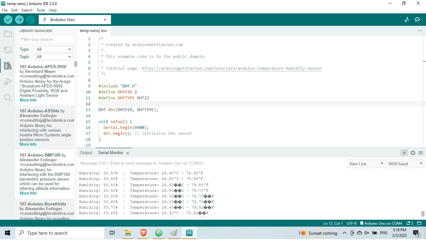
With the following code i was able, through Ardiuno, to check if the sensor was reading correctly the temperature and humidity generated through the heater.
I first tested the code building a simple circuit like explained in the picture and code below:
add picture sensor and breaboard
Code for testing the sensor
I integrated the heater, the fan and the sensor in the circuit to check if the sensor was able to detect the right temperature in the environment generated through the heating element. As the system requires ventilation, I needed also to connect the fan later on.
From the code below you can see the program I made:
When the temperature reaches 35 degrees, the heater stops working.
Code
/*
 * Created by ArduinoGetStarted.com
 *
 * This example code is in the public domain
 *
 * Tutorial page: https://arduinogetstarted.com/tutorials/arduino-temperature-humidity-sensor
 */

#include "DHT.h"
#define DHTPIN 2
#define DHTTYPE DHT22
#define ADC_VREF_mV    5000.0 // in millivolt
#define ADC_RESOLUTION 1024.0
#define PIN_LM35       A0
#define LED 13
#define Relay 4

int adcVal = analogRead(PIN_LM35);
float milliVolt = adcVal * (ADC_VREF_mV / ADC_RESOLUTION);
float tempCLM = milliVolt / 10;
float tempFLM = tempCLM * 9 / 5 + 32;
/*
 * Created by ArduinoGetStarted.com
 *
 * This example code is in the public domain
 *
 * Tutorial page: https://arduinogetstarted.com/tutorials/arduino-lm35-temperature-sensor
 */


DHT dht(DHTPIN, DHTTYPE);

void setup() {
  Serial.begin(9600);
  dht.begin(); // initialize the sensor
  pinMode(LED,OUTPUT);
  pinMode(Relay,OUTPUT);
}

void loop() {
  // wait a few seconds between measurements.
  delay(2000);

  // read humidity
  float humi  = dht.readHumidity();
  // read temperature as Celsius
  float tempC = dht.readTemperature();
  // read temperature as Fahrenheit
  float tempF = dht.readTemperature(true);

  // check if any reads failed
  if (isnan(humi) || isnan(tempC) || isnan(tempF)) {
    Serial.println("Failed to read from DHT sensor!");
  } else {
    //Serial.print("Humidity: ");
   // Serial.print(humi);
   // Serial.print("%");

    //Serial.print("  |  ");

    Serial.println("Temperature Sensor: ");
    Serial.print(tempC);
    int adcVal = analogRead(A0);
  // convert the ADC value to voltage in millivolt
    float milliVolt = adcVal * (ADC_VREF_mV / ADC_RESOLUTION);
  // convert the voltage to the temperature in Celsius
    float tempCLM = milliVolt / 10;
  // convert the Celsius to Fahrenheit
delay(500);
  // print the temperature in the Serial Monitor:
    Serial.println("Temperature LM35: ");
   Serial.print(tempC);   // print the temperature in Celsius
   Serial.print("°C");
delay(500);

if(tempC<32.0){
  digitalWrite(Relay,HIGH);
  digitalWrite(LED,HIGH);
}else if(tempC>36.0){
  digitalWrite(Relay,LOW);
  digitalWrite(LED,LOW);
}


  }
}
Tesing the LCD display :
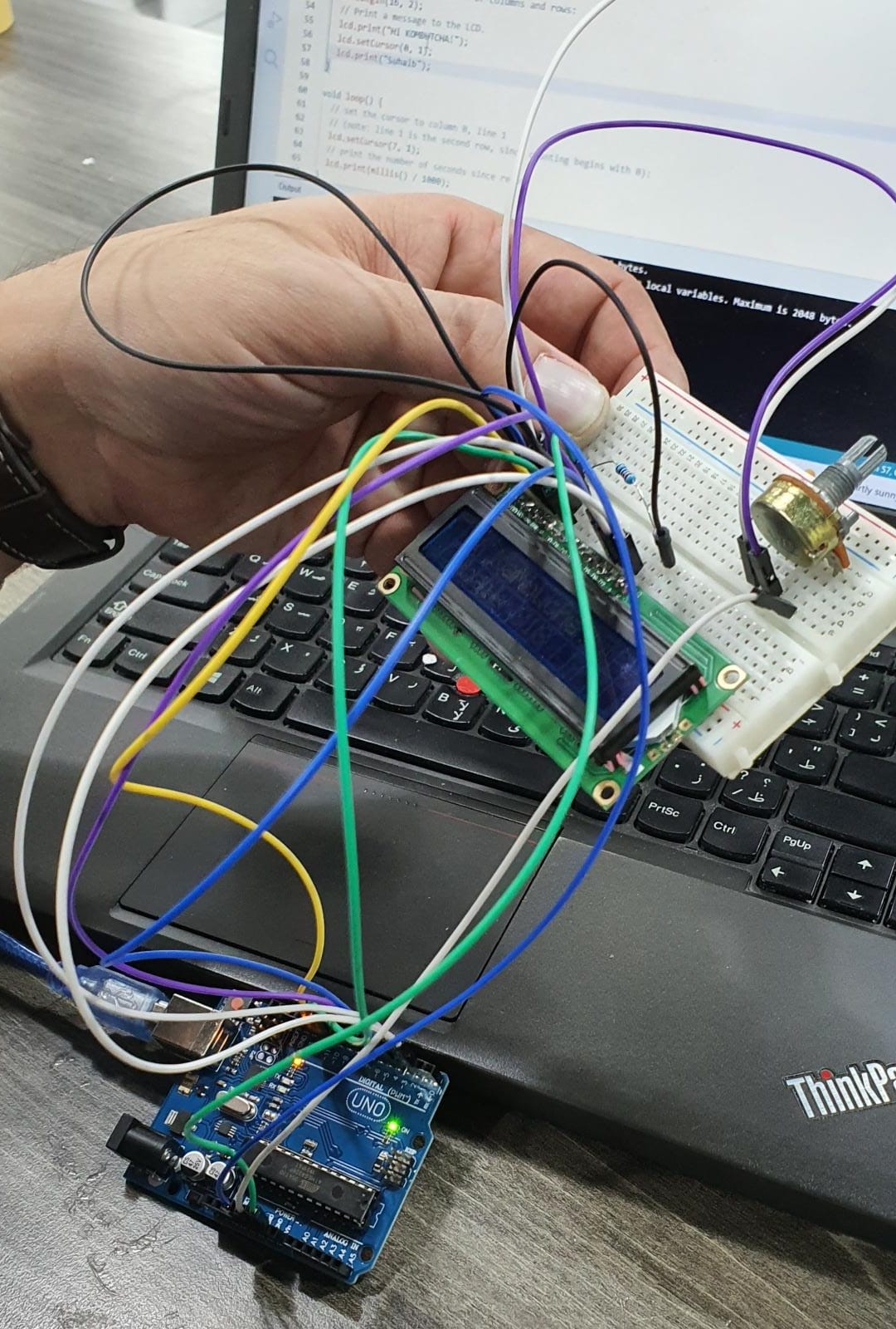
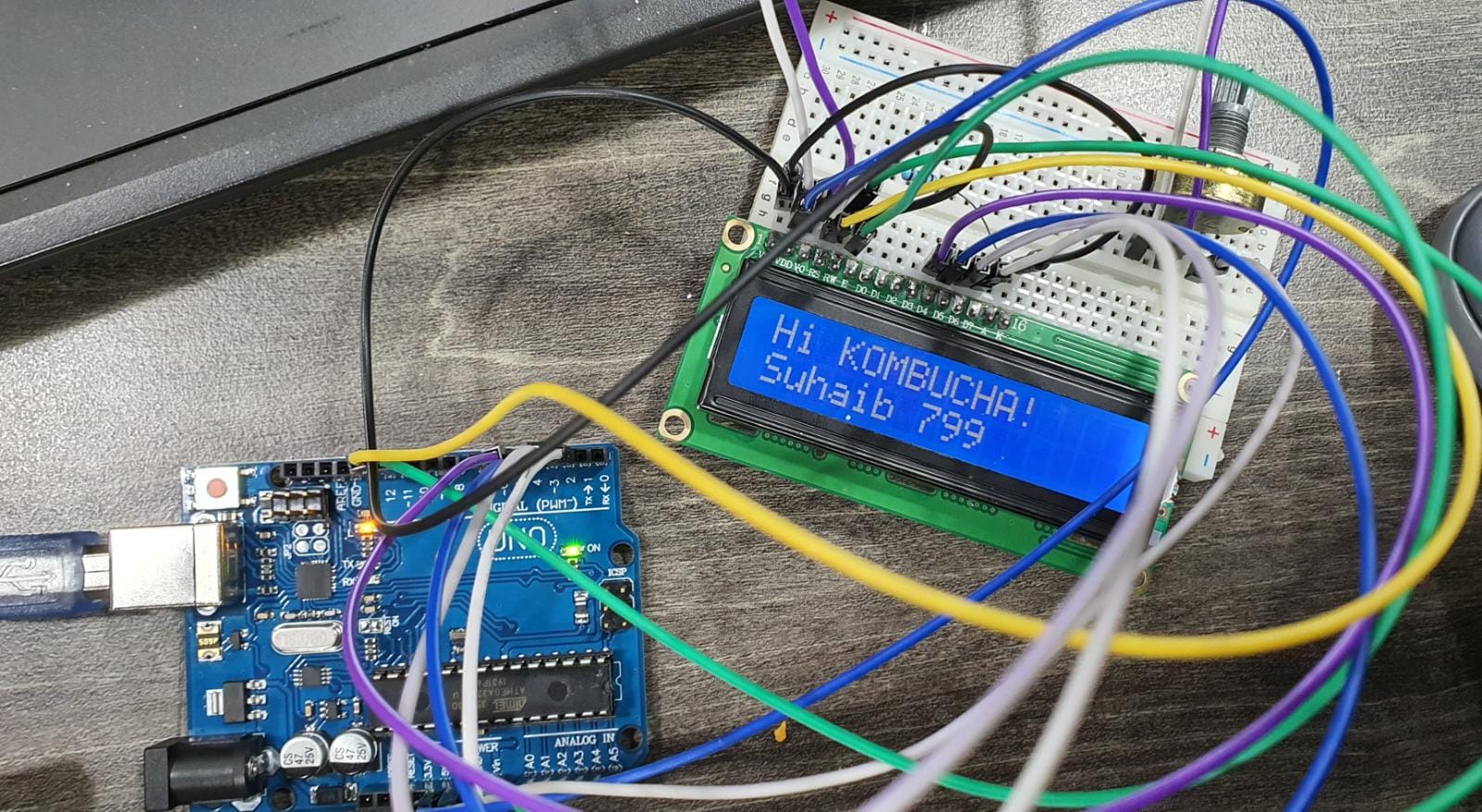
below is the schematic connection of LCD and Arduino UNO:
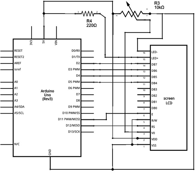
Using the schematic above I connected the LCD through Arduino to learn how to diplay numbers and messages.
Code
/*
  LiquidCrystal Library - Hello World

 Demonstrates the use a 16x2 LCD display.  The LiquidCrystal
 library works with all LCD displays that are compatible with the
 Hitachi HD44780 driver. There are many of them out there, and you
 can usually tell them by the 16-pin interface.

 This sketch prints "Hello World!" to the LCD
 and shows the time.

  The circuit:
 * LCD RS pin to digital pin 12
 * LCD Enable pin to digital pin 11
 * LCD D4 pin to digital pin 5
 * LCD D5 pin to digital pin 4
 * LCD D6 pin to digital pin 3
 * LCD D7 pin to digital pin 2
 * LCD R/W pin to ground
 * LCD VSS pin to ground
 * LCD VCC pin to 5V
 * 10K resistor:
 * ends to +5V and ground
 * wiper to LCD VO pin (pin 3)

 Library originally added 18 Apr 2008
 by David A. Mellis
 library modified 5 Jul 2009
 by Limor Fried (http://www.ladyada.net)
 example added 9 Jul 2009
 by Tom Igoe
 modified 22 Nov 2010
 by Tom Igoe
 modified 7 Nov 2016
 by Arturo Guadalupi

 This example code is in the public domain.

 http://www.arduino.cc/en/Tutorial/LiquidCrystalHelloWorld

*/

// include the library code:
#include <LiquidCrystal.h>

// initialize the library by associating any needed LCD interface pin
// with the arduino pin number it is connected to
const int rs = 12, en = 11, d4 = 5, d5 = 4, d6 = 3, d7 = 2;
LiquidCrystal lcd(rs, en, d4, d5, d6, d7);

void setup() {
  // set up the LCD's number of columns and rows:
  lcd.begin(16, 2);
  // Print a message to the LCD.
  lcd.print("hello, world!");
}

void loop() {
  // set the cursor to column 0, line 1
  // (note: line 1 is the second row, since counting begins with 0):
  lcd.setCursor(0, 1);
  // print the number of seconds since reset:
  lcd.print(millis() / 1000);
}
Notes :
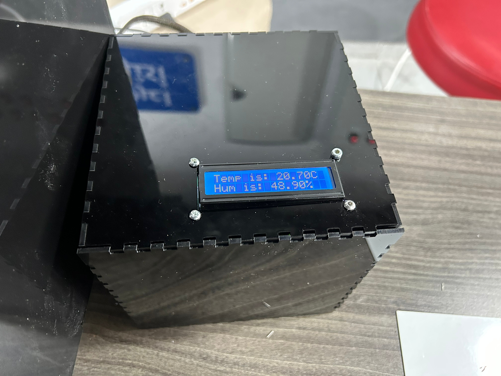
"Electronic box" I used Boxes.py](https://www.festi.info/boxes.py/?language=en) software for quick design I adjusted it on Inkscape to make a LCD Screen & wire hole as below picture :

You can find the box file in the final prototype tab : under final fabrication files.
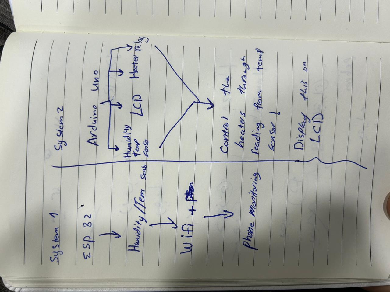
"Connecting the electronics"
I seperated electronics into two systems ,first system i coonect first humidity & tempreture sensor with esp32 , Another system i connected the heater , humidity & tempreture sensor,Relay ,LCD monitor & DC fan with Arduino UNO as below pictures with note that DC fan & heater will be connected to the relay then realy is connected to the arduino.