5. E-textiles
Research
Back to elementary school time and start to remembering electrical circuit ,wires and batteries, etc.. and connect the dot to make something with E- textile .
- Above picture taken from Sirar Khawaja
References & Inspiration
I had explore some of the previous student in textile :
Action Start :
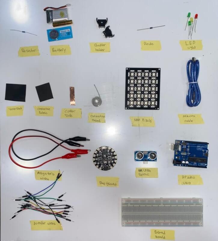
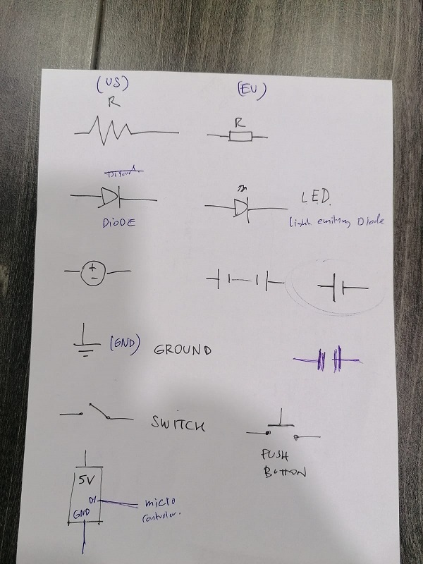
As for this week assignment we have to make one analog circuit and digital one ,but before some primary lesson to catch up about electronic as seen in picture below :
Multimeter:
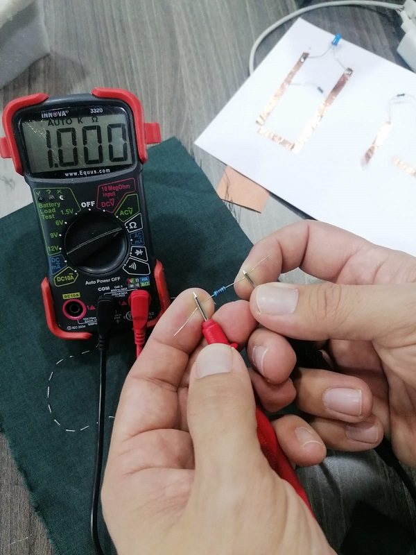
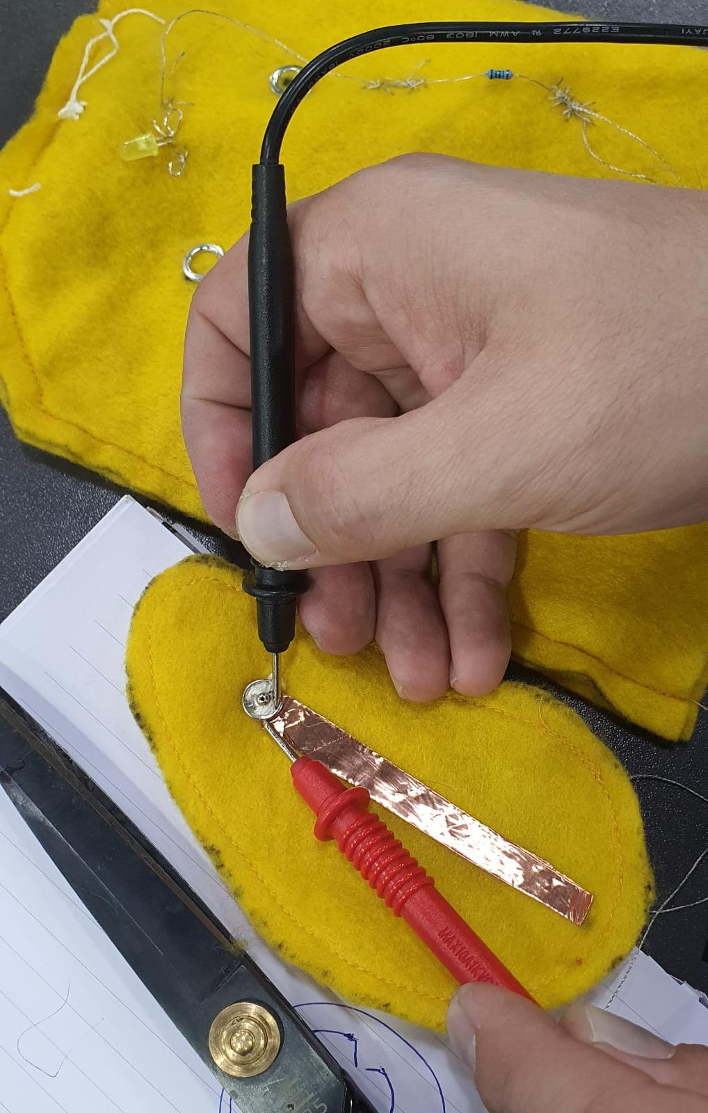
A very important measuring instrument that can measure multiple electrical properties from * Checking Voltage (1.5V, 6V, 9V, 12V) * Checking Resistance through touching both ends of the resistance .and unit value is in the Ohm's * Conductivity: A conductive material means it allows electrical current to pass through it, so when you touch a material with both wires and the multimeter peeps sound appear that means it is conductive thorough the line between both point ,and if no peep sound appear that mean this two points in the line that where selected the electrical current can be pass through the line .
Below pictures can explain more of the Multimeter work: * Checking resistance in the multimeter:
Checking Conductivity in the multimeter:
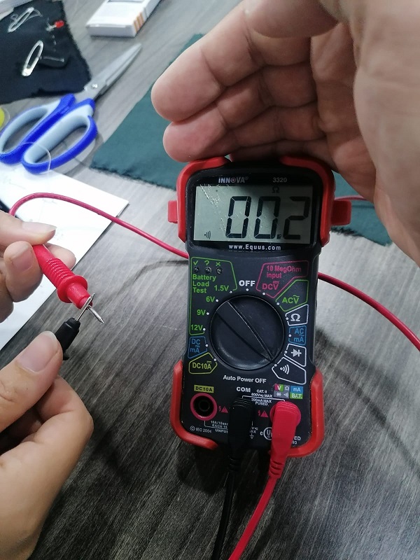
Checking Voltage in the multimeter:
Process and workflow
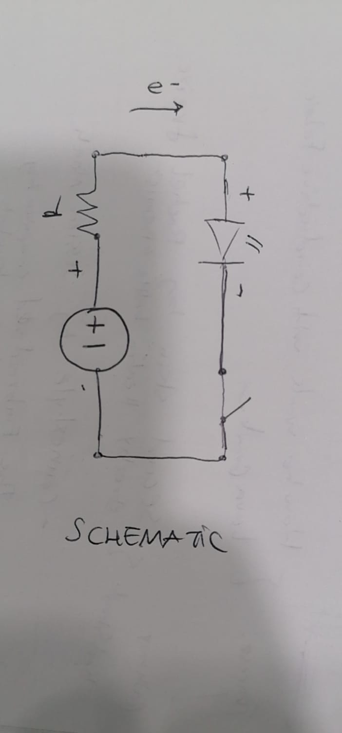
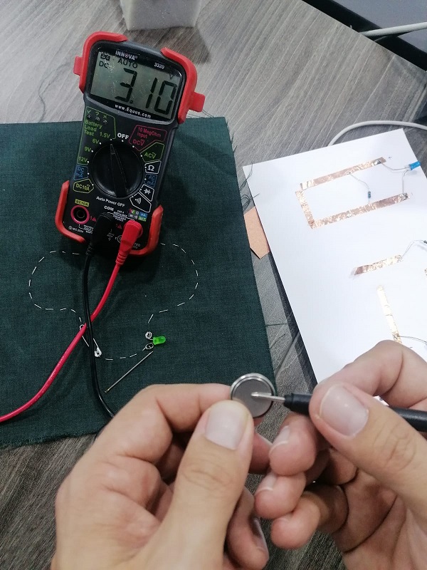
Analog circuit:
We made two closed circuits one parallel mode and one series mode using (copper tape, LED light, resister and a 3V battery) by soldering the LED light legs over copper tape and soldering resistor over copper tape as well .
then make a switch and check if light turn on and off . as below pictures :
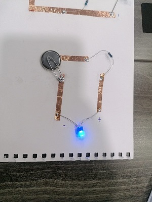
- Parallel mode closed circuit
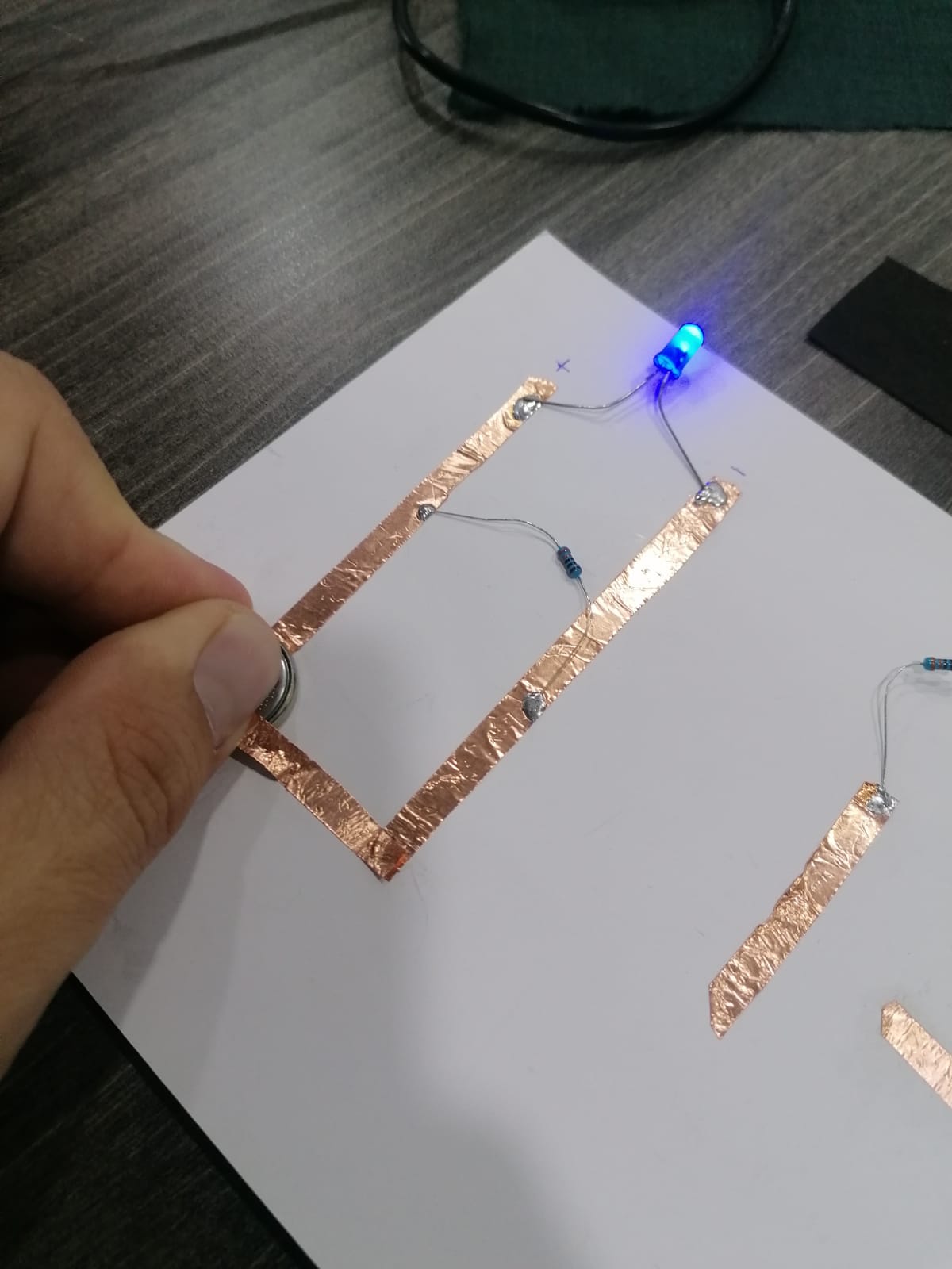
- Series mode closed circuit
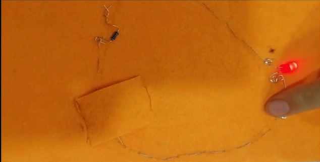
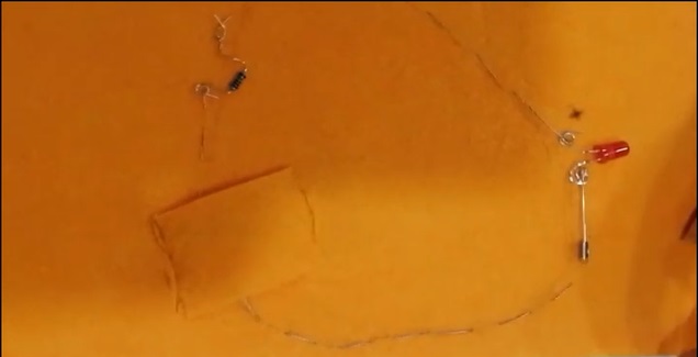
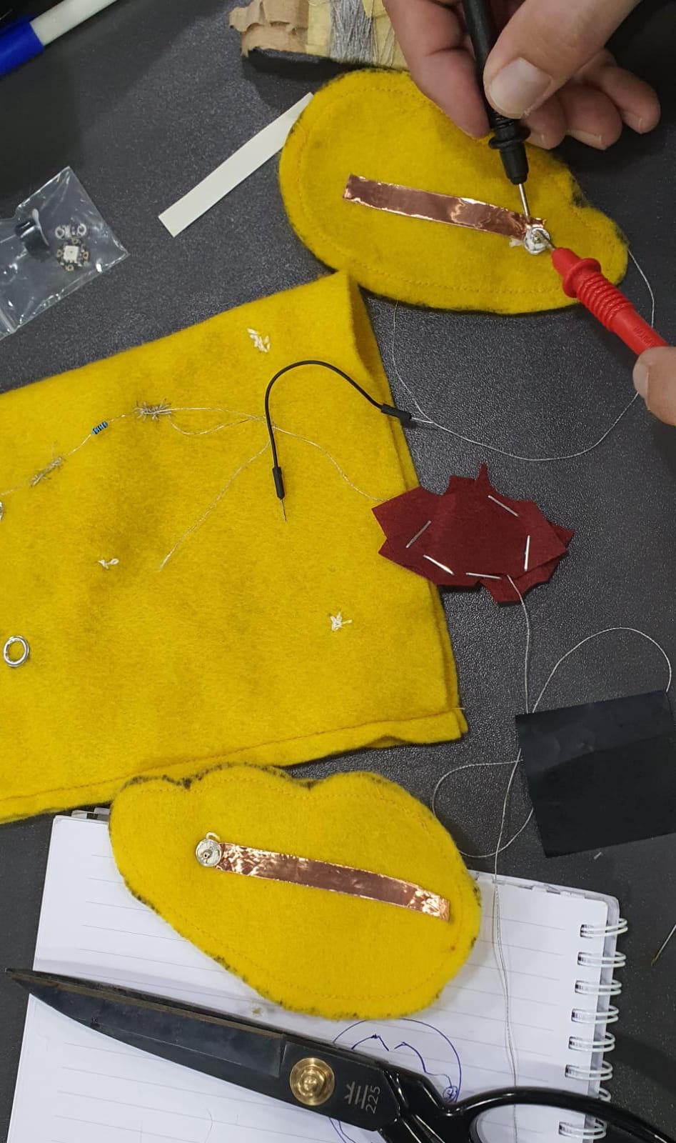
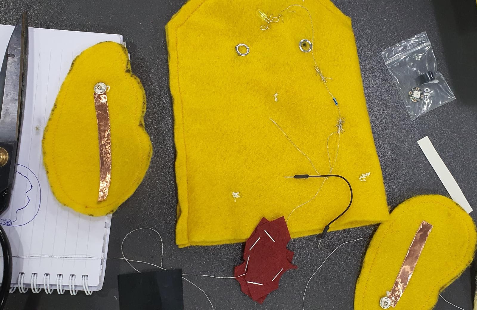
Building Circuit on Fabric :
1- Starting with sewing on conductive thread on the fabric then join LDE from the positive side until connected the negative side in the same way and continue sewing until have closed shape,
2- After that I made a pocket to cover the battery with a thread in the meddle so the battery can touch the thread to close the circuit.
3- Then connect the resistor to the conductive thread .
4- using the clip as manual switch So when we touch the clip with conductive thread it becomes a closed circuit and the LED lights turn on and when we release our hand from the clip it become open circuit and light turn off .
below pictures & video can explain more about work process:
Picture :
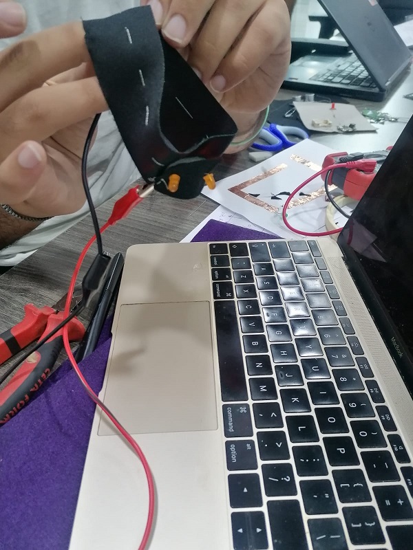
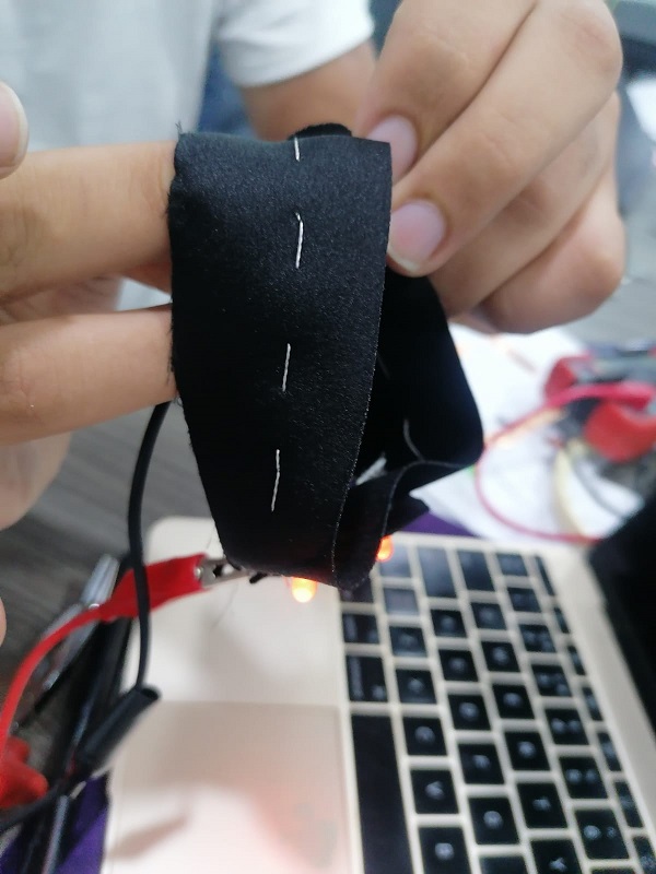
Other experiment using crocodile clips on fabric :
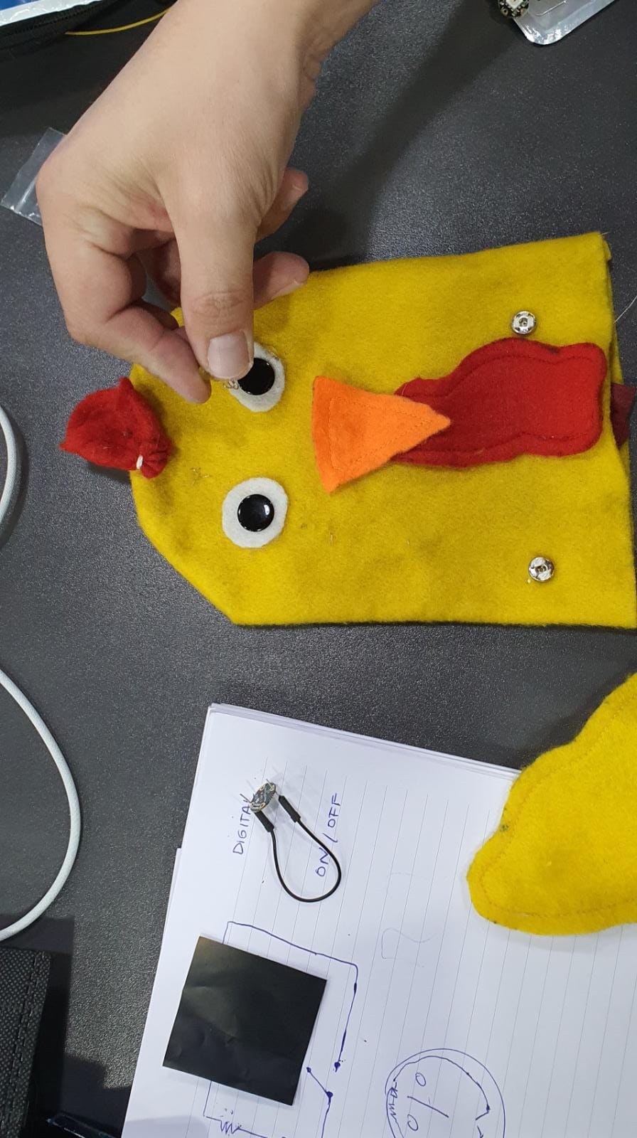
Duck Picture:
I made a circut in used fabric to teach kids closed circut,below is the picture of sawing :
video:
Duck video :
Using Arduino :
Arduino is and open-source Prototyping platform that allows users to create an interactive electronic object, Arduino code is written in C++
To use Arduino we need a microcontroller board based on a microchip that reads Arduino, a breadboard, jumper cables, resistance & some LED lights
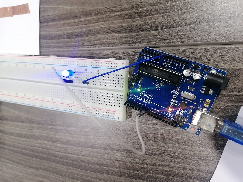
Recommendation : in order to keep Arduino UNO device function completely don't change the direction of the cable path before you shutdown the code other wise it will be broken .
Example of the Arduino Code :
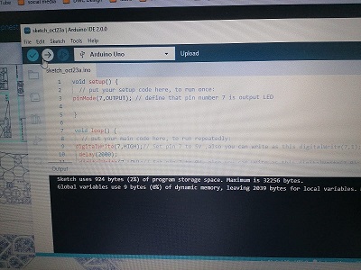
The setup function runs once when you press reset or power the board
initialize digital pin LED_BUILTIN as an output.
  pinMode(LED_BUILTIN, OUTPUT);
}

The loop function runs over and over again forever
void loop()

  digitalWrite(LED_BUILTIN, HIGH);

  delay(1000);

  digitalWrite(LED_BUILTIN, LOW);

  delay(1000);
}
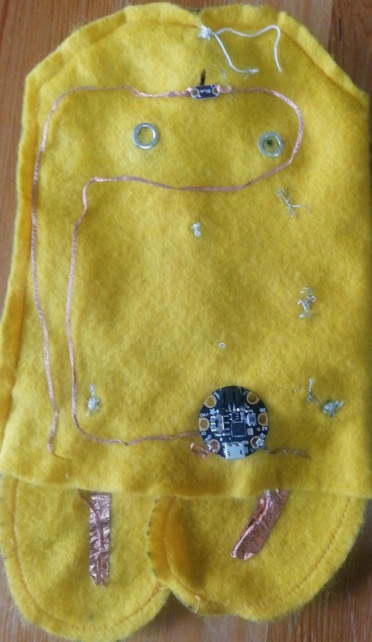
Second experemnt for digital switch :
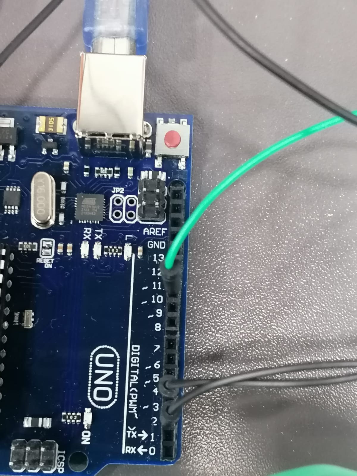
below pictures is a circuit that attached inside of the dug fibric pice which has a blue lilypad LED connected to Adafruit Gemma M0 microcontroller. I used a copper wire connect pieces. I left a gap in the circuit for the switch (dug wings) and make a hole in each wing to let the copper wire enter so when dug wing clappemd the led light will turn on. note i used a trasparent type to stic the copper tape in the dug fabrig insited of stitch it and work fine .
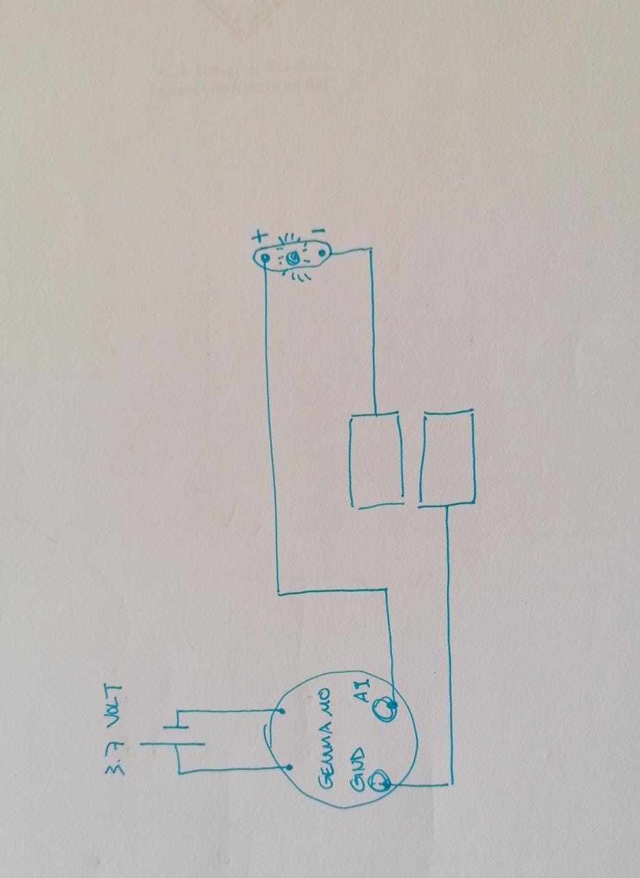
Digital Switch Code :
I used the same code i used before in the dug experemnt for blink the led light ,just this time we add the GEMMA microcontroller which is contain inside it a resistor so no need to add a seperate resistor as we did before in the previous experement.
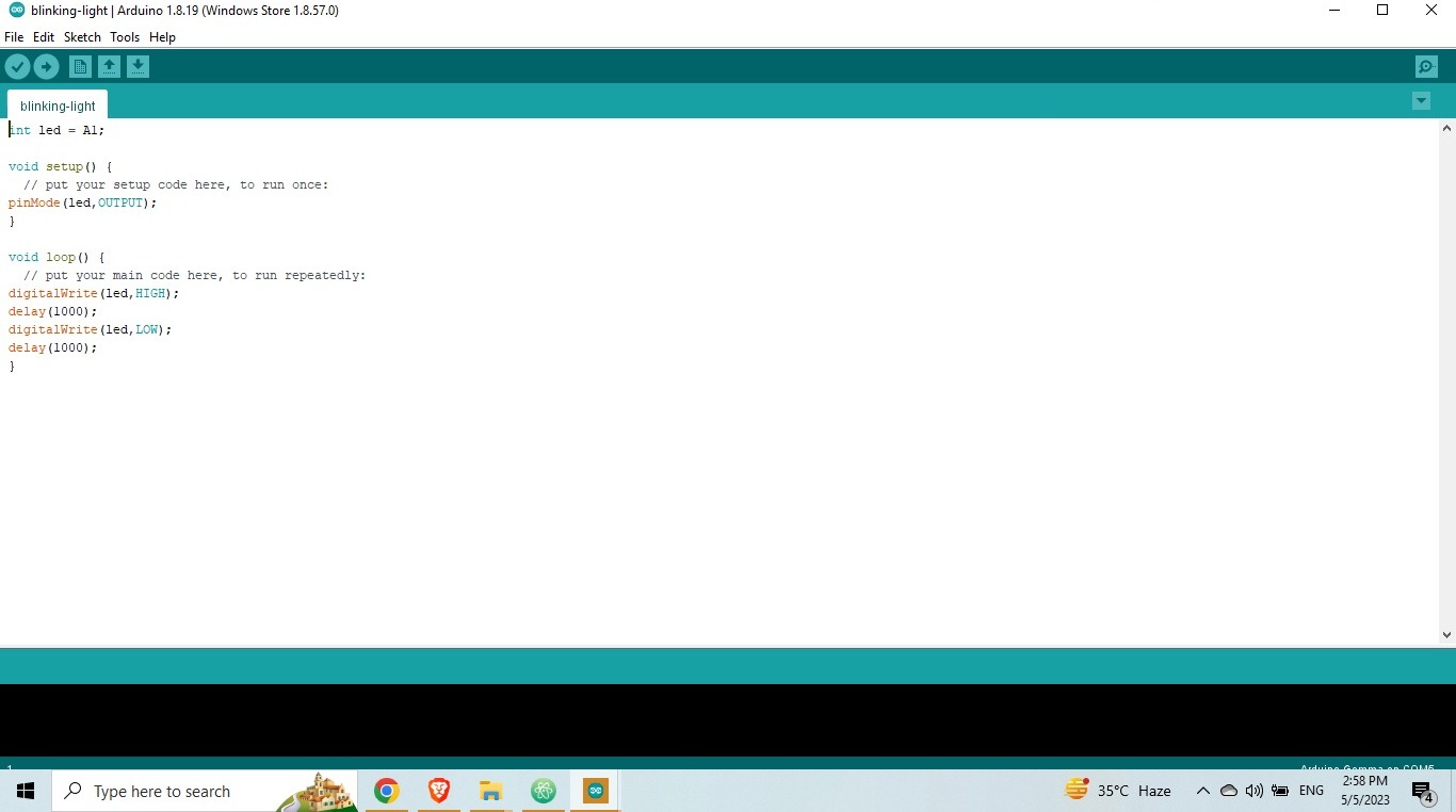
int led = A1;

void setup() {
  // put your setup code here, to run once:
pinMode(led,OUTPUT);
}

void loop() {
  // put your main code here, to run repeatedly:
digitalWrite(led,HIGH);
delay(1000);
digitalWrite(led,LOW);
delay(1000);
}
Vedio2:
- below is the vedio of the experiment :
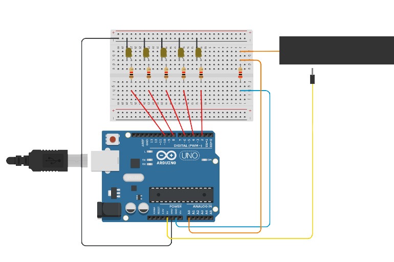
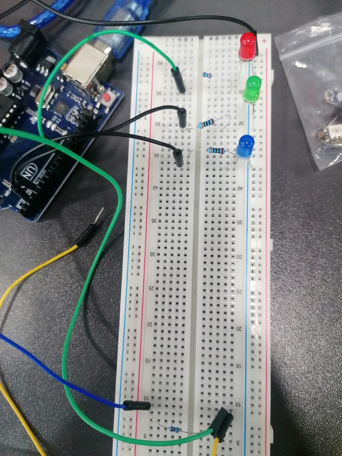
Analog Switch:
the objective of Analog switch is playing with various signal ranges , i follow Ala janbek documentation to make a potentiometer, which contain a grey rectangle from velostat fabric. a 2K ohm resistors,3 LEDs, Arduino board, breadboard, and jumper wires.
below the digram of the analog switch:
Analog switch Code :
int resist = A0;
int light_1 = 2;
int light_2 = 4;
int light_3 = 6;


void setup() {
  // put your setup code here, to run once:
  Serial.begin(9600);
  pinMode(light_1, OUTPUT);
  pinMode(light_2, OUTPUT);
  pinMode(light_3, OUTPUT);

}

void loop() {
  // put your main code here, to run repeatedly:

  int r = analogRead(resist);
  delay(500);
  Serial.println(r); //0-1000 R
  if ((r < 1020) && (r >= 10)) {

    if ((10 < r)&&(r <= 250)){
      digitalWrite(light_1, HIGH);
      digitalWrite(light_2, LOW);
      digitalWrite(light_3, LOW);

    }

    if ((250 < r) && (r <= 350)){
      digitalWrite(light_1, LOW);
      digitalWrite(light_2, HIGH);
      digitalWrite(light_3, LOW);

    }

     if ((0 < r)&&(r <= 1)){
      digitalWrite(light_1, LOW);
      digitalWrite(light_2, HIGH);
      digitalWrite(light_3, LOW);

    }
        if ((20 < r) && (r <= 30)){
      digitalWrite(light_1, HIGH);
      digitalWrite(light_2, LOW);
      digitalWrite(light_3, LOW);

    }
        if ((360 < r ) && (r <= 650)){
      digitalWrite(light_1, LOW);
      digitalWrite(light_2, LOW);
      digitalWrite(light_3, LOW);

    }
    }

   else{
   digitalWrite(light_1, LOW);
   digitalWrite(light_2, LOW);
   digitalWrite(light_3, LOW);

  }

}
analog switch vedio :
After many attempts i was able to successfully to finish the assiment below vedio: .