HOW TO
This is a walkthrough of the building process. If anything is not clear or you have any questions feel free to reach out viw email rileycox000@gmail.com

MATERIALS
- Note: I encourage you to be scrappy in building this! I was use a lot of scraps for these materials rather than ordering all new online. I will link the materials similar to ones I used but please feel open to replacing things based on personal preferences.
| Qty | Description | Price | Link | Notes |
|---|---|---|---|---|
| 2 | 5mm Plywood | 22.18 € | Link | |
| 2 | 3mm Acrylic | 30.00 € | Link | This link is to a multipack |
| 5 | .5" Wood dowels | 5.69 € | Link | This link is to a multipack |
| 1 | PLA | 17.00 € | Link | |
| 1 | Arduino Uno | 24.00 € | Link | |
| 2 | High Torque Servo | 16.00 € | Link | |
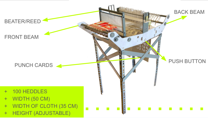
| 1 | Push button | 10.00 € | Link | Any kind of pushbutton can be used, I used a light up arcade one |
| 1 | Copper wire | 12.00 € | Link | This link is to a multipack |
| 1 | Perf board | 5.69 € | Link | This link is to a multipack |
| 1 | 10K ohm resistor | 1.99 € | Link | This link is to a multipack |
| 1 | 5v power supply | 7.59 € | Link | |
| 1 | Perf board | 5.69 € | Link | This link is to a multipack |
| 2 | 3/8" Threaded rods | 8.99 € | Link | This link is to a multipack |
| 1 | Pack of screws and nuts | 10.88 € | Link | This link is to a pack |
| - | Card stock | 5.69 € | Link | This link is to a multipack |
| - | Thread and yarn | - € | This is up to personal preference! | |
| 4 | T slotted aluminum angle bars | - € | Link | I found the ones I use in the trash but linked something similar, I think these are easy to find in cheap furnature |
TOOLS
- 3D Printer
- Laser Cutter
- Saudering Iron
- Drill
- Clamps/ Woodglue
- Sand paper
SOFTWARE
- Slicing software for your printer (I used PrusaSlicer)
- Laser cutting software (I used Lightburn)
- Rhino or other 3D design platform
- Arduino
LETS GET STARTED
Here you'll find a guide to start putting this thing together!
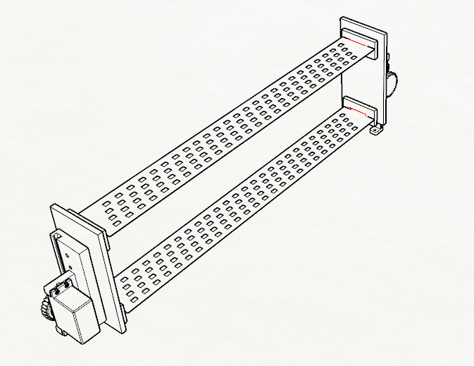
3D PRINTING, LINEAR ACTUATORS
I'm new to 3D modeling functional parts but luckily I was able to find this really nice linear actuator model on Thingiverse by Potentprintables. I slightly modified their design for the high torque servos. I printed this in PLA. I used the threaded nuts and bolts to put this together so I could take it apart again. However, I did glue the gear to the servo head.
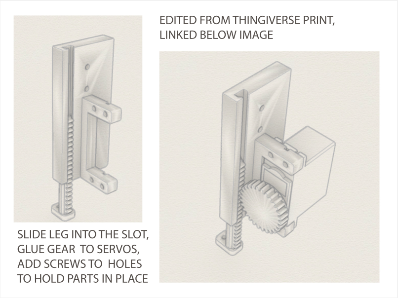
My edited version of this file can be found here ()
- Note: I would like to go back and edit this to make the gear larger to add a larger range of motion to produce a larger shed in the threads, but this works for now
CONSTRUCTION/ LASER CUT PARTS
NOTE Although this is my most resolved prototype, I was still figuring out things and adding elements as I constructed this. Not all holes for nuts and bolts are included in the original laser cut file, you will need to drill some. I will work on making a more finalized file that includes all screw/bolt holes to be cut my the laser but for now you can follow along and add them with the drill a long the way.
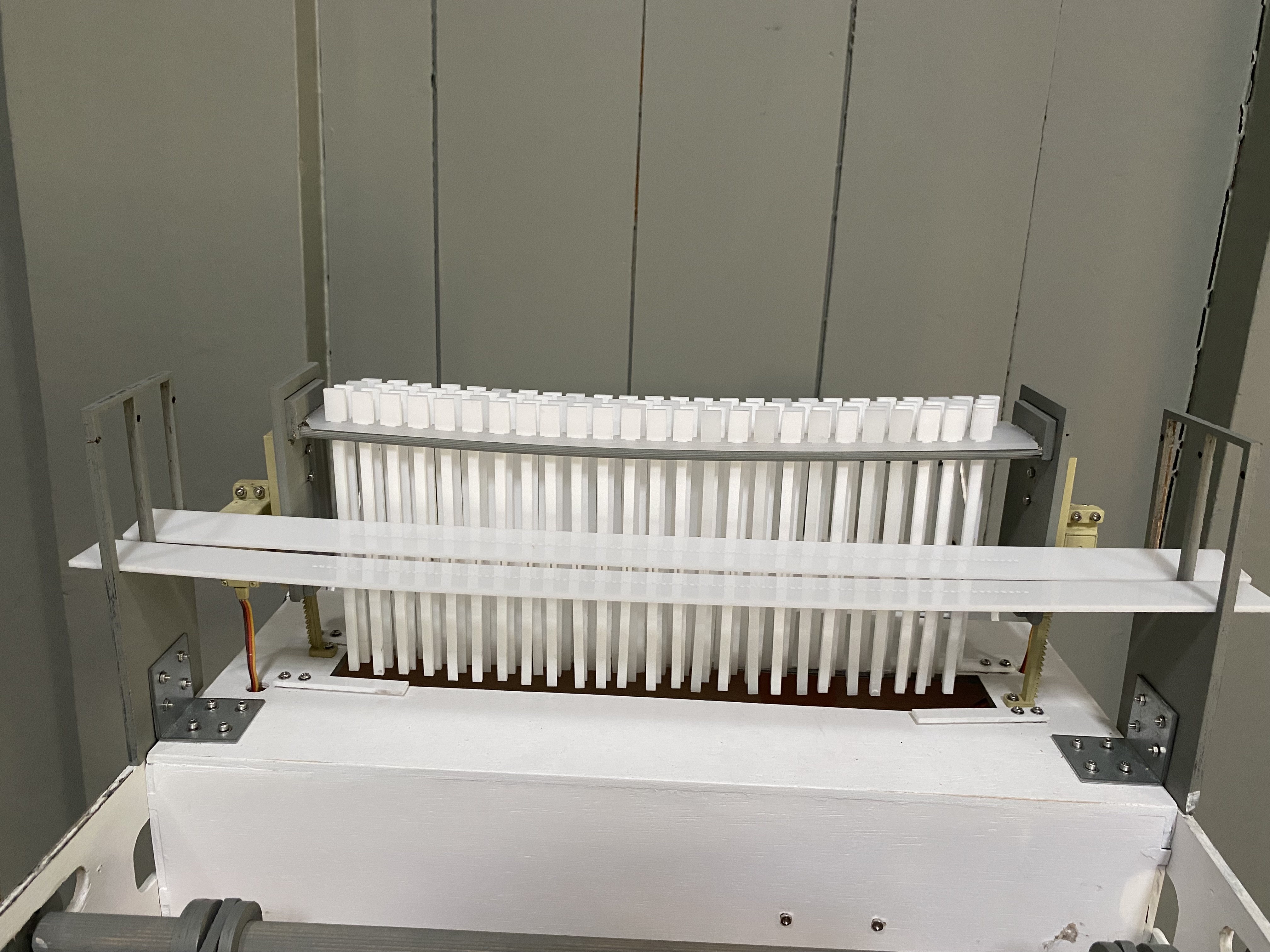
HEDDLES

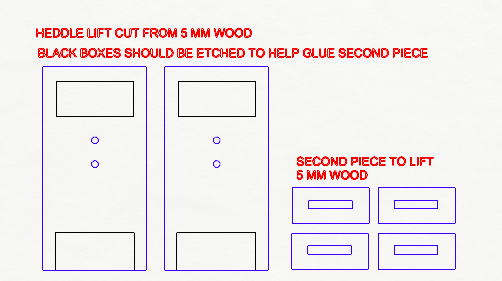
- This is what will attach the Linear Actuator to the heddles/heddle holder
- Cut out of your 5mm thick wood and use wood glue to attach the smaller squares to the areas that are etched
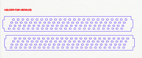
- Next cut out these pieces which which hold the heddles. I used some scarp acrylic for this but wood would also work and would probably be more structurally sound. The acrylic I used had a bit of a bed to it with the heddles added.
- It should be 4-5 mm thick though to fit into the slots of the lift. I used a bit of glue to secure it in the slots.
It should come together like this!
- Next you need to cut the heddles themselves. I used 3mm acrylic
- You will need 100 of these
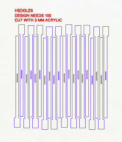
- These should slide into the holding mechanism and be able to move up and down with ease.
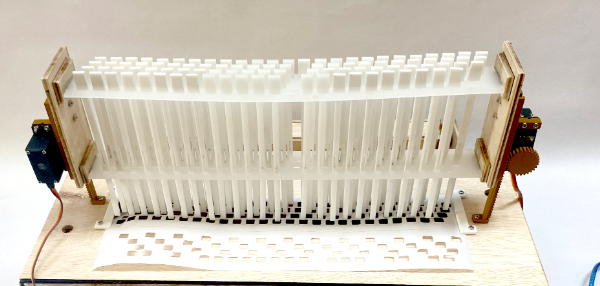
NOTE I later added a small dowel for extra supprt under the top beam. You will probably not need this if you use stronger material (like wood instead of acrylic).

WOOD BASE
- These should be cut out of 5mm thick wood
- I clamped and glued these together to make a box structure
- I drilled the legs of the linear actuator into the wood
NOTE Servos should be facing oposite directions!! the linear actuators will not be symmetrical
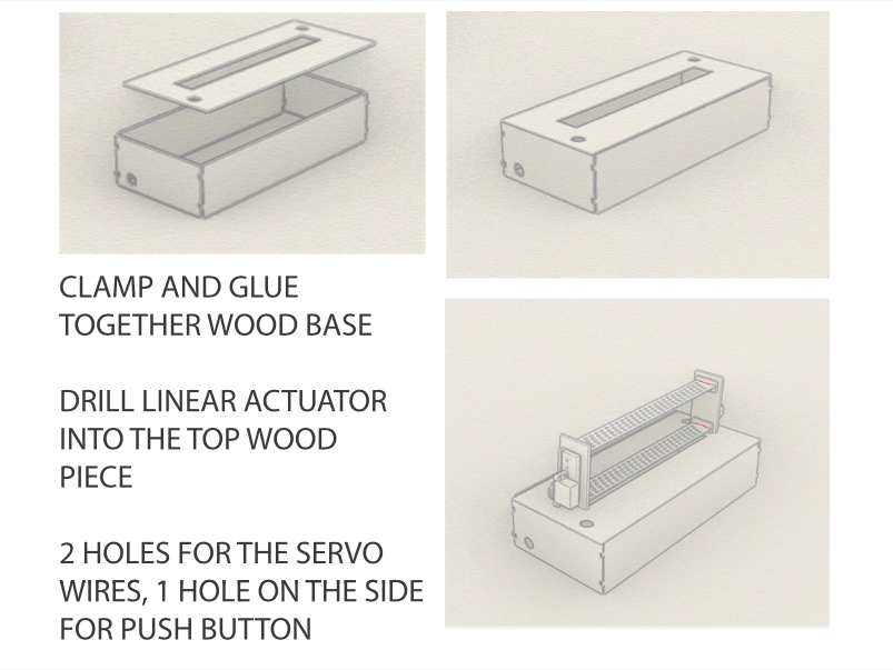
- I also added small acrylic arms to hold the puchcards in place. The pieces have 4 washers under them to give them some height to allow the cards to much through.
It should come together like this...
NOTE The wooden box is the only large constructed part that is not able to be deconstructed (I glued mine together with wood glue). Feel free to change this if you like, however when taking my loom apart tp travel, the wooden box base works as a nice holding containing for the smaller parts.
WOOD ARMS
- These are also cut out of the same 5mm wood
- There is one file that is longer and holds the front beams and beater
- The shorter file holds the back beam
NOTE I may continue to make edits to these as I am not fully happy with the movement of the beater at the moment. I will update if I continue protoyping
These will then be drilled into the sides of the box base

BEAMS
The front and back beams are made with wooden dowel rods bought from the hardware store. You will need 6 of these in total, 4 for the front and back beams. 5 of these should be cut to be around 50 cm, and 1 should be cut to be 36 cm (this is for the reed which will come later)


-
To secure each beam in place, a circular laser cut shape is drilled into the rod through the hole in the loom arm. You will need 8 of these circular shapes, 6 for the front and back beams and 2 for the beater.
-
For the beams that need will not move (the beam at the highest point of each arm) drill two screws into the other holes provided in circlular wood piece to secure it to the arms of the loom
-
The two beams on each side at the lowest point of the arm, will need to move to advance the warp.
-
For the moving beam there will be one side of the rod that uses a circular end and another that uses a rachet gear. This ensures you can rotate it and secure it in place after doing so.
You can find the file for the ratchet here
You can find the file for the circular caps for the ends of the rods here
Note This laser cut file needs to be glued in stacks after it is cut. A similar design could be 3d printed as a complete object but I found that stacking and gluing together the wood pieces was faster and worked fine for me.
The gear shape gets a circular shape glued on top to allow for a better grip when turning it. The comma shaped piece sits inside a piece which consists of a c shape and small circle glued to eachother. The comma shape needs to be close enough to the gears to touch it as it turns.

These should be drilled into the one side of the dowel rods on lowest point of the loom. The other side of the rod should just be capped with another circular piece.
BEATER
This beater design is a bit of a work in progress. I still feel like it could be more structurally sound.
-
I cut 102 of these out of 1.5 mm acrylic.
-
I then slid them onto a metal bar using 2 washers to space them out.
You can find the file here for the acrylic reed pieces
Find the files for the wooden support here
Should come together like this ...

And cap the dowel rods witht he remaining circular pieces. Make sure this is not too tight as you will need a range of movement with this.

SHAFTS FOR PLAIN WEAVE
I added these on to the design later so that I didn't need a ton of plain weave punch cards in between any patterned card. Its a pretty lowbrow, thread heddle lifing system. I will talk more about make the thread heddles in the warping section.
-
I used acrylic to make the 2 beams but this could also be subbed for wood. The acrylic looks nice but has a bit too much bend to it and makes lifing the threads a bit annoying to get a good sized shaft.
-
The holder for this was cut of wood and holds the beams in place. You will need an angle bracket to secure this to the wooden box frame
It should come together like this...
And when later on after you warp the loom you can make thread heddles on alternating strings so when you lift these you are able to get a quick plain weave.

The file for the wooden holder is Here
The file for the plain weave lifts is Here
LEGS
-
I found these metal angle beams in from a shelf someone was throwing away. I wanted to pick something for the legs that would allow for adjustable height. This allows for this loom to be a floor loom or table top loom
-
I added some laser cut x beams for structural support. I used more nuts and bolts that allow for me to take apart and put them back together again.
ELECTRONICS
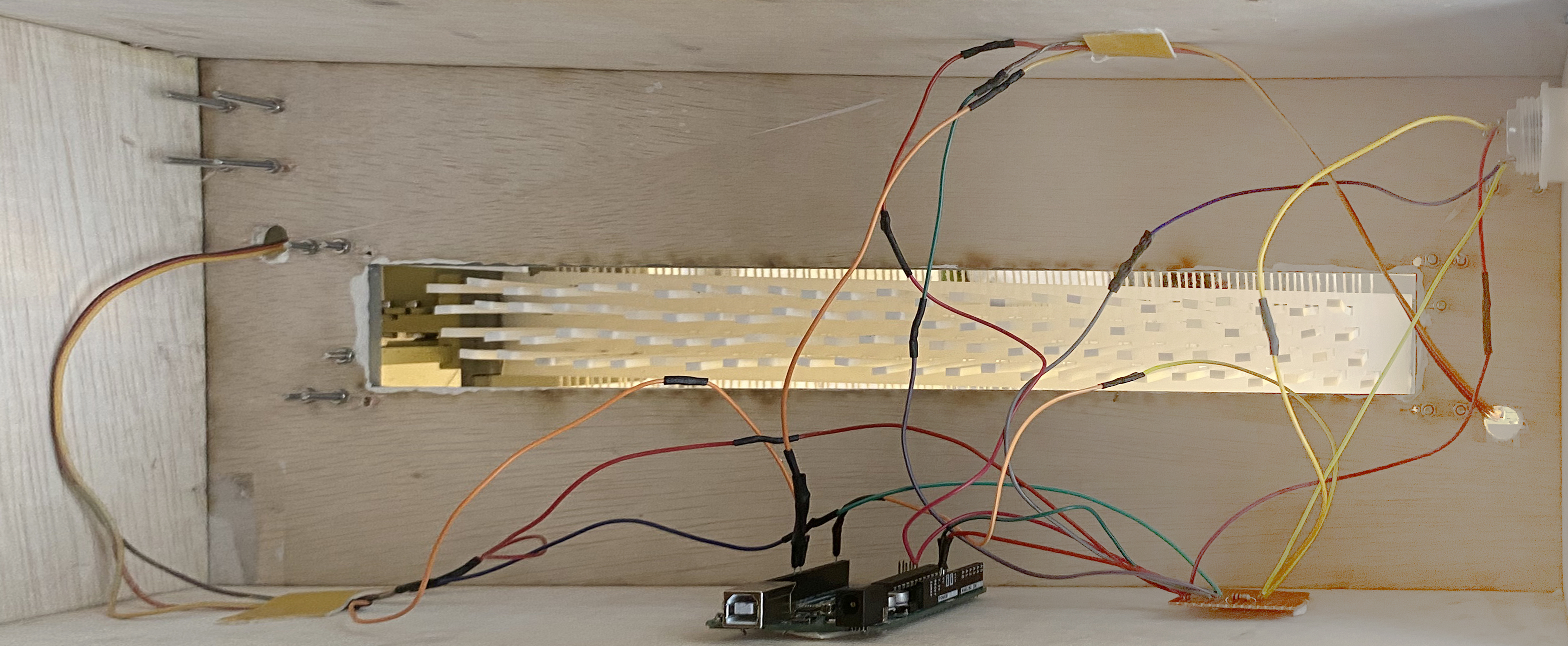
I use two high torque servos attached to an arduino uno with a push button to control them
#include <Servo.h>

// Define servo and button pins
const int servoPin = 9;
const int buttonPin = 2;

Servo myServo;

#include <Servo.h>

// Define servo and button pins
const int servoPin1 = 9; // Pin for first servo
const int servoPin2 = 10; // Pin for second servo
const int buttonPin = 2;

Servo myServo1;
Servo myServo2;

// Variables to track servo position and button state
int servoPosition1 = 0;       // Initial position for first servo
int servoPosition2 = 0;       // Initial position for second servo
int buttonState = 0;         // Variable to store the button state
int lastButtonState = 0;     // Variable to store the previous button state
bool servoDirection = true;  // True: move from 0 to 90, False: move from 90 to 0

void setup() {
  // Attach servos to the corresponding pins
  myServo1.attach(servoPin1);
  myServo2.attach(servoPin2);

  // Set button pin as input
  pinMode(buttonPin, INPUT);
}

void loop() {
  // Read the state of the button
  buttonState = digitalRead(buttonPin);

  // Check if the button is pressed and the previous state was not pressed
  if (buttonState == HIGH && lastButtonState == LOW) {
    // Change the servo direction
    servoDirection = !servoDirection;

    // Move the servos based on the direction
    if (servoDirection) {
      // Move from 0 to 90 degrees for both servos
      for (int pos = 0; pos <= 90; pos += 1) {
        myServo1.write(pos);
        myServo2.write(pos);
        delay(15);
      }
    } else {
      // Move from 90 to 0 degrees for both servos
      for (int pos = 90; pos >= 0; pos -= 1) {
        myServo1.write(pos);
        myServo2.write(pos);
        delay(15);
      }
    }
  }

  // Update the last button state
  lastButtonState = buttonState;
}
^ This is the code I used
This tutorial was really helpful in setting up the large pushbutton I used pushbutton
- Here is a diagram of the circuit
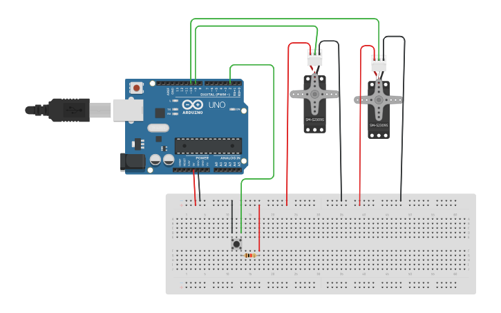
- All the wires are hidden inside of the box enclosure
Also the box file does not include a laser cut hole for the pushbutton. I drilled one the size of my button and this may vary depending on which kind of button you use.
PATTERNING/ PUNCHCARDS
NOTE This part is a bit time consuming. I would like in the future to try to work with a python script to do less patterning work. I would say this is a bit like writing binary by hand at the moment.
- You can see here the order in which I threaded the loom (This is an aerial diagram of the heddles). (1,2,3,4,1,2,3,4 etc...) so I made a system of numbered rows each with 4 strings
- I start with a pixel image with exactly 100 pixels across because that is the amount of threads I have. I go row by row and make note of which where all the black pixels are. these will be the threads that need to be dropped, meaning there needs to be a hole in that spot.
-
This is the part that is quite tedious but I then write down the corrdinates of al the black pixels in relation to the heddles. (for example: I need to drop the 3rd and 4th thread on the 3rd row so I would write 3-(3,4) )
-
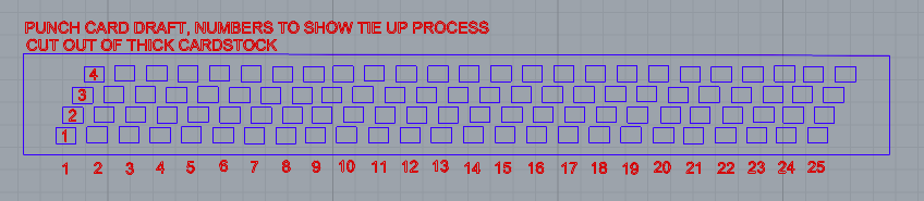
Then I go into rhino and delete all punch card holes except for the coordinates I have written
-
I etch the number of the cards to keep track while patterning. I also like to add a bit of extra paper at the start and end of the pattern so that the first and last card has some more structural integrity.
-
This gets laser cut with the red lines being a dashed folding line. I can't always fit a pattern on just one sheet of paper but it works fine to have multiple that are taped together.
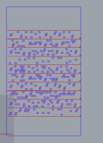
- While weaving I have been weaving a shot of plain weave between every patterned throw. Similar to an overshot pattern because of the floats in my paterns i've done so far. Also because my EPI is so low, it is helpful to weave each card twice before moving on to the next in the row if you are not weaving with a super thick yarn.
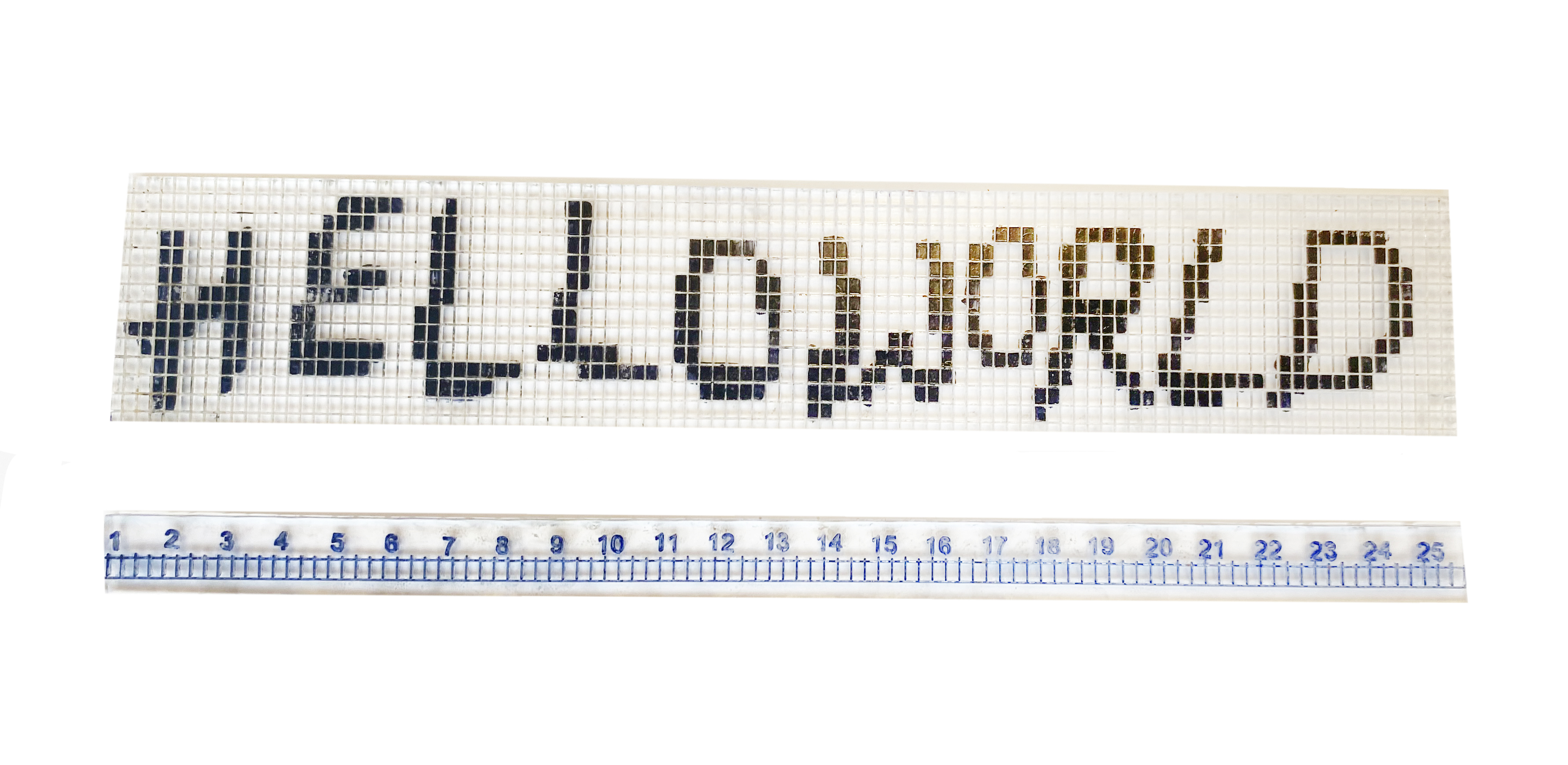
This is my helloworld text pattern here
There are a lot of floats on the back of this weaving but it was needed to mak ethe text legible.
I will keep updating this as I make patterns in the future
WARPING
-
If you have never warped a loom before I will link some tutorials here that will explain the process better than I could.
-
You will need some kind of warping board and a slayer. These are not tools I designed for this project, though I would like to make open source versions of.
-
If you don't have a warping board you can use some other kinf of peg board. I used this rack we had in the lab for spools of thread.

-
A slayer is just a hooked tool that helps get warp threads through the eye of the heddle. This isn't necessary but does help make it faster.
-
On this loom there are 100 threads so keeo that in mind when measuring/counting your warp threads.
For measuring out the warp This tutorial is really helpful
If you do not own a warping board,
For threading and warping This tutorial is really helpful
WEAVING NOTES
-
When you're ready to begin weaving I recomend using your plain weave shafts with a thick yarn/wool to get tension started
-
lift the shafts in alernating order, (1,2,1,2,1,2...) to create plain weave
-
When youre ready to start a patern press your button to lift up your heddles and slide your first punch card in
-
lower the heddles with the push button into the holes. You may need to jiggle the paper around until all that need to fall in can
-
Now use a pick up stick to lift the threads that did not drop to reate a large enhough shed to pass your shuttle through.
-
In between each patterned pass, I would throw a plain weave one in with a non colored yarn
-
You have to manually advance the punch crads by hand for now but keep track of which card you are on. I would each card twice in a row to make a correctly sized pixel