5. E-textiles
Research
weekly assignment
Check out the weekly assignment here or login to your NuEval progress and evaluation page.
get inspired!
Check out and research alumni pages to betetr understand how to document and get inspired
- Alice Sowa
- Ieva Maria Dautartaite
- Loes Bogers TextileLab Amsterdam 2019-20_
- Sara Alvarez TextileLab Amsterdam 2020-21_
- Kate Reed
- Diane Wakim
- Vicky Luan
Add your fav alumni's pages as references
E-Textiles Notes
Circuits:
This week was a bit of a struggle to get to grips with for me, I had done some basic circuits before in school but none of this had stayed with me really so I had to start at the beginning with electrics. Here are some of the basics that we learnt this week:
Voltage – electrical pressure between 2 points (potential) Current – rate at which charge flows Resistance – the amount of material that resists the flow of current
Parallel vs series – series all components are connected in one path and share the voltage, parallel all components are connected in different paths and the current is split
Digital vs analogue - digital is binary (e.g. on/off) and information is translated in binary code, analogue has a range of options and information is translated through varying electric pulses
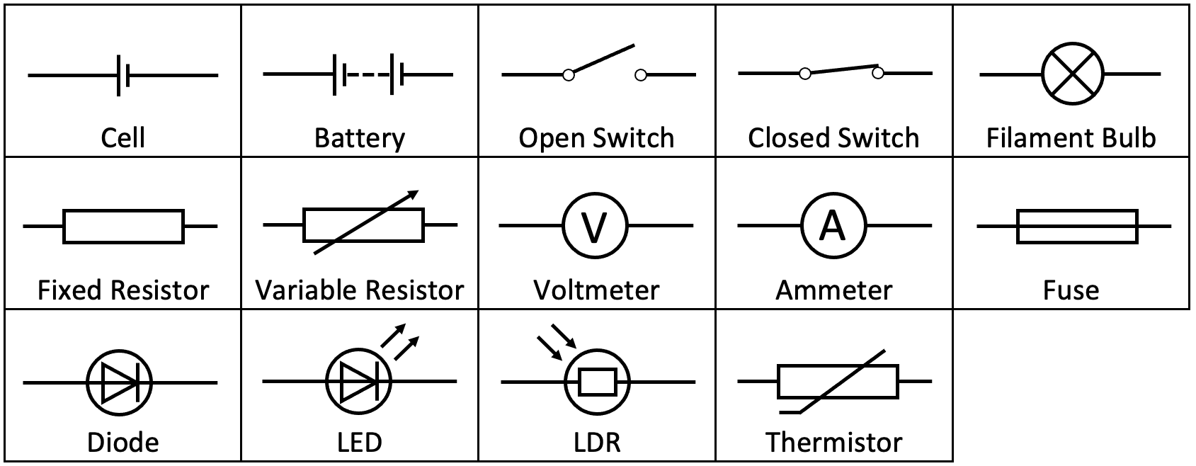
Components in the box run through:
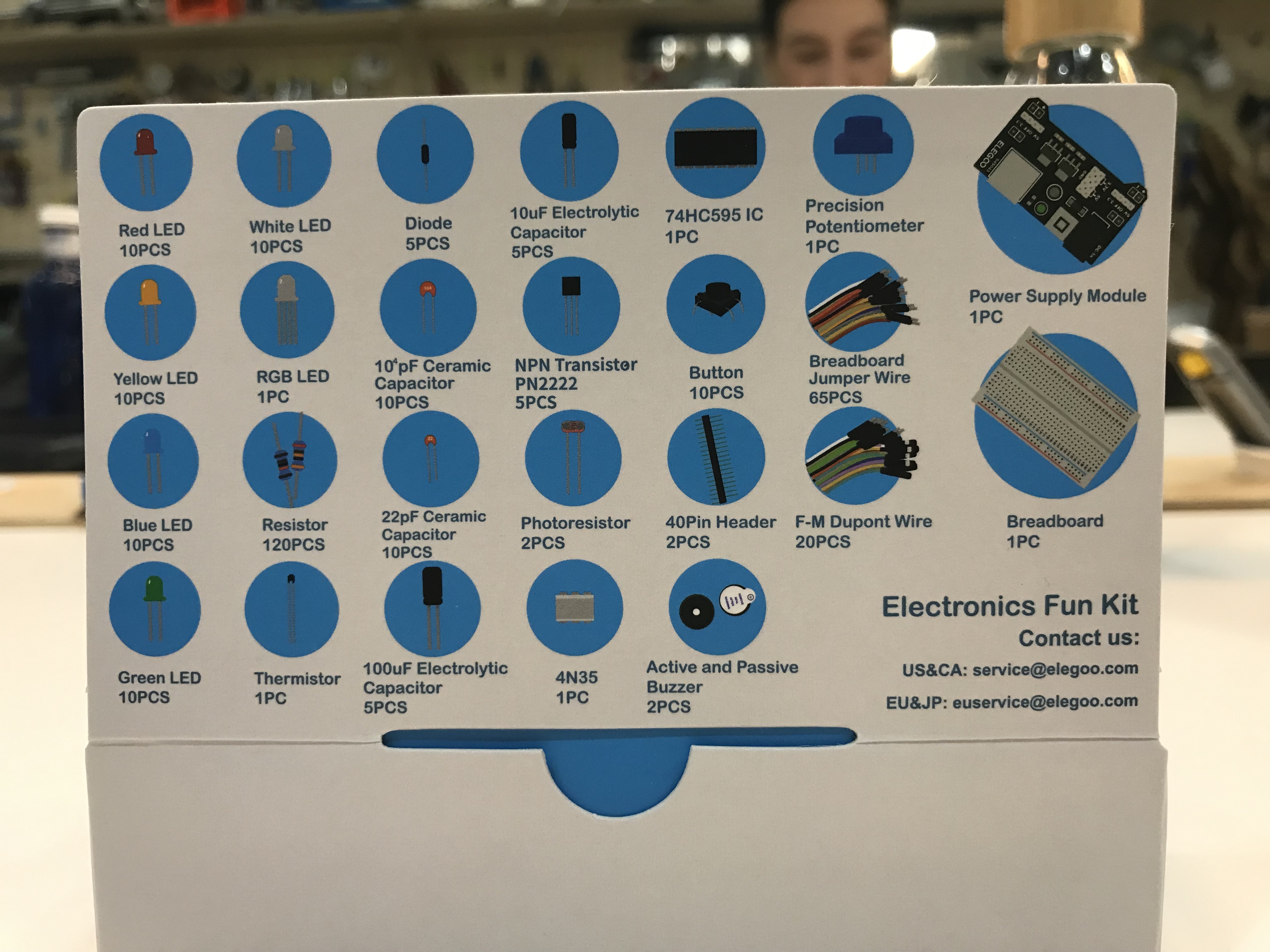
- LED – light emitting diode (small light bulb)
- Resistor – used to regulate the current flow in the circuit
- Diode – only allows current to flow in one direction through it
- Capacitor –
- Transistor –
- Button – used to close or open the circuit, switching on or off the flow of current
- Buzzer – emits sounds when current flows through it
- Potentiometer – variable resistor that increases and decreases the flow of current
- Breadboard – used to build and test temporary circuits
- Multimeter – used to measure the flow of current, voltage and amps
First Circuit attempts with Gerard:
In the session we had with Gerard, we began looking at making our own circuits on the breadboard. We did this first by making a very basic circuit that just had a battery and a single LED. Initially we used the blue LEDs as these ones don’t need a resistor with the 3v batteries. Then I tried setting up 3 LEDs in series on the board and adding a switch to the circuit.
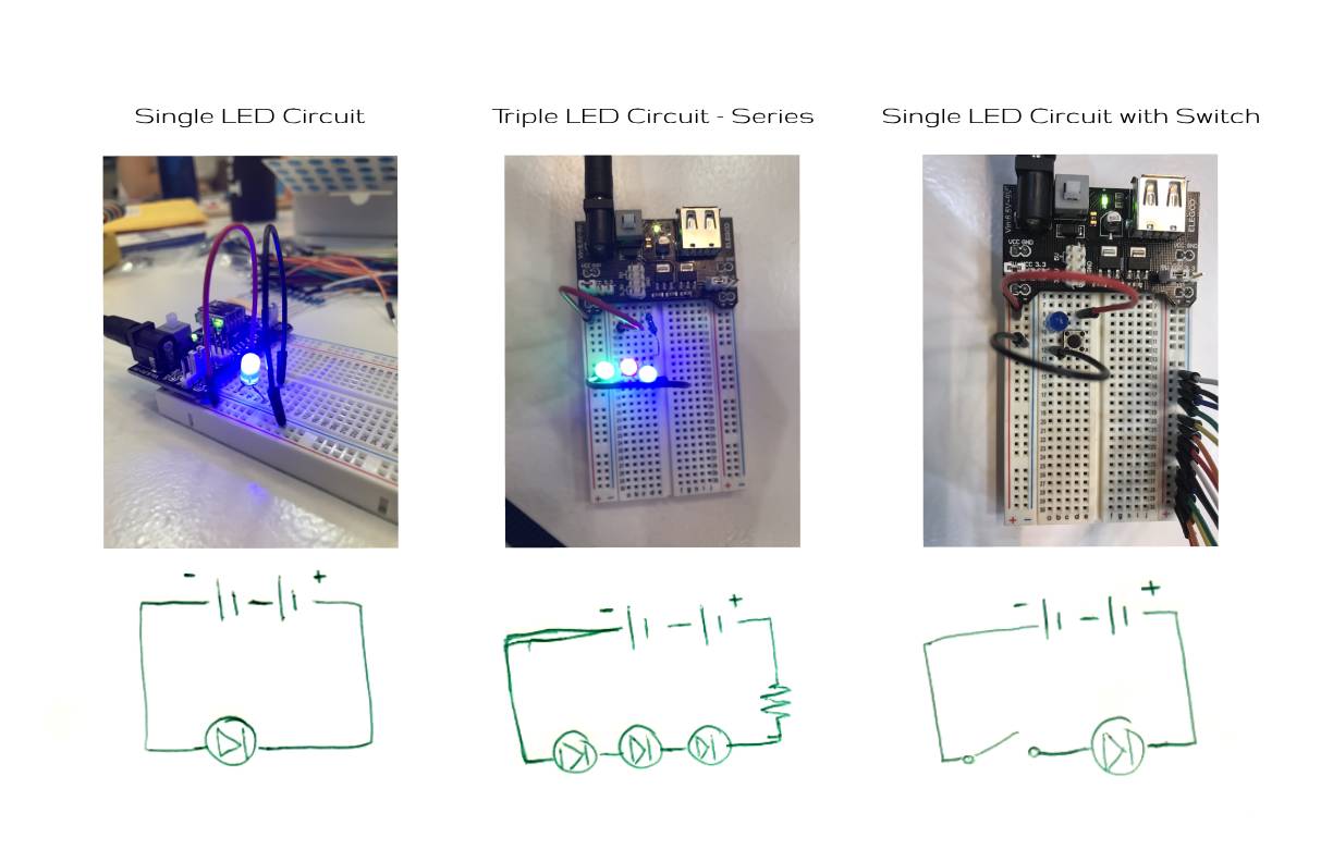
We also learnt about resistors and when they are needed. I struggled with this a lot and it took me a while to get select the right resistors for my circuits that didn’t just make the LEDs turn off. We used this resistance calculator to work out what was needed for which LEDs:

(In a probably not fully correct but understandable way) Resistors are needed to help the circuit use up all the voltage from the battery so that when the circuit reaches the negative side of the battery it is at 0. For example, the blue LED doesn’t need a resistor with the 3v battery as it uses 3v but the other LEDs, especially the red one do need a resistor as they use fewer volts – 1.8v for the red so we need to use a resistor that uses the equivalent of 1.2v if we are using a 3v battery.
Making a textile switch with Cit
Making a pressure sensor:
In the class with Cit, we began looking at taking the circuits we were making off the breadboard and adding them to textiles. We began by making a textile pressure switch. To do this, we sandwiched a bit of foam with some holes cut out in between two pieces of conductive material so that they only touched when pressed. One of these bits of conductive material was attached to the positive side of the battery and the other to the LED and negative side of the battery. I sewed this all closed in between two pieces of neoprene to finish it. This switch worked very well in this circuit.

button 1 from Ruby Lennox on Vimeo.
Linking the Arduino
Next we wanted to link the switch we had made to a computer so that we could collect a data input from it and define various outputs from this this data. We used the XIAO ESP32C3 for this linked to the Arduino software.

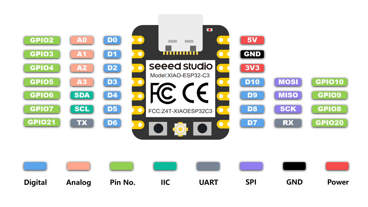
Initially we just wanted to be able to read some data from the switch so we the circuit we made just joined the switch to the XIAO without and LEDs or anything. We did briefly get this working and the serial monitor in Arduino was showing 0s or 1s depending on if the switch was being pressed or not. The code we used for this was:
int buttonState;

void setup (){
Serial.begin(9600);
pinMode(D7, INPUT);
}

void loop (){
buttonState= digitalRead(D7);
Serial.println(buttonState);
}
Making my own switch
After this we began experimenting with different ways of creating textile switches. We had a wide range of conductive materials at the lab including yarns, threads and fabrics – including Velostat and Eeontex.
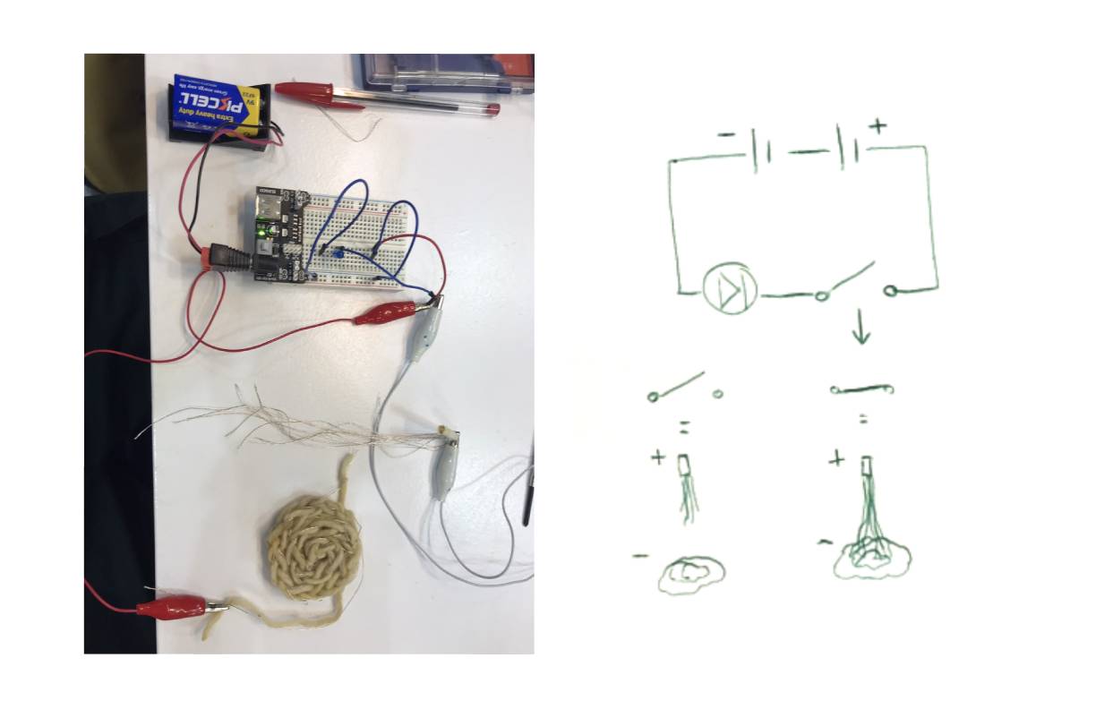
Tassel switches
I wanted to see how loose the connections between the two ends of the switch could be. With this tassel switch they would only touch when held at a certain angle or if they were moved around a lot and there was no built-in way for them to stay connected without someone holding them together so the that light was flickering on and off a lot.

tassel switch from Ruby Lennox on Vimeo.
With this switch, I was looking at how to combine different textures constructions in a switch. I used a full tassel and a section of knit with conductive thread through it to see how the different densities of the conductive thread would affect the ease of use of the switch. This one was a lot less temperamental than the one above.
tassel switch 2 from Ruby Lennox on Vimeo.
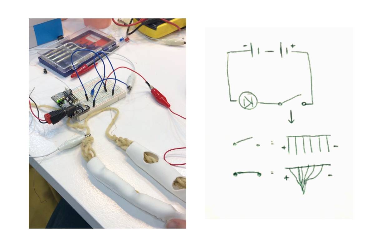
Tube switch
For this one, I wanted to try to make one where most of the conductive material was hidden and it needed to be very deliberately turned on. To do this, I knitted some normal yarn with a strand of conductive thread and put these behind a tube of neoprene with a few holes cut in. This meant that they needed to be specifically aligned and then a lot of pressure added to make the threads touch.
tube swithc from Ruby Lennox on Vimeo.
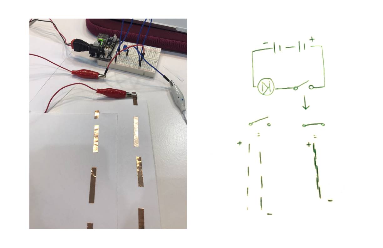
Broken line switch
This one was a quick prototype of how stitching could be used as a switch by itself so that the fabric didn’t need anything bulky added to become a switch. It worked well and it it was done with conductive thread on 2 separate bits of fabric, it wouldn’t need to be so well aligned so it would be very easy to use.
broken line switch from Ruby Lennox on Vimeo.
Final Idea Process
Initial attempt – fixes
For my final switch this week, I wanted it to be a bit more interactive than just the light being on or off. I thought, a way to do this would be to have multiple buttons that would turn on different lights when closed in different combinations. E.g. if only the bottom 2 buttons were closed then the blue light would come on but if you closed all 3, the red one would also come on.

I made a quick paper and thread prototype of how I imagined I could make this and connected it to some lights on the breadboard. This did turn on the lights when some of the threads where joined but it was not in the combinations I had thought it would be and which light was turning on was not how I had planned at all.
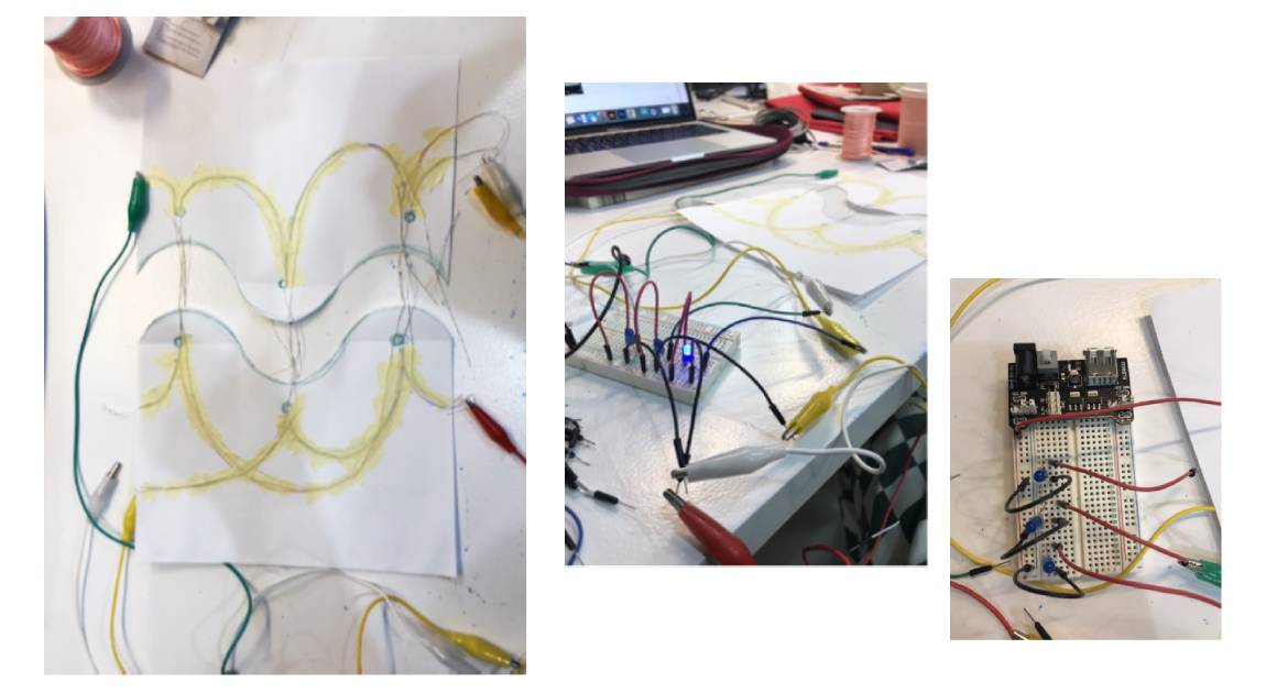
Gerard said this was probably because my wires were too close together and it was probable causing a short circuit when I tried to connect only specific ones and that my circuit on the breadboard was wired wrong. To fix this, I would need to have the 3 separate colour circuits going through different buttons not the same 3 as this would cause them to short. This seemed like it would end up either very complicated to wire and with too many buttons for this week or I would just have 3 very simple separate circuits.
RGB light
Julia suggested that I replace the 3 different lights with 1 RGB light and simplify the different switches from combinations to individual switches. I hadn’t used the RGB LEDs yet so I made a quick circuit on the breadboard to get to grips with the different legs they had and how it worked.

With the RGB light, I only needed one circuit with 3 switches connected in parallel that all came back to the same LED rather than 3 separate circuits with individual LEDs. This worked well so I decided to try making the actual textile sample.
Initial textile prototype
When I had made the textile prototype and connected it to the battery, it worked very well when only one switch was closed but it did not mix the colours very well when 2 or more where closed as I had hoped. I found that the red in the LED was overpowering the other colours here as it used the least voltage to power so with the same voltage as the other 2 colours it was a lot brighter. To try to even them out, I needed to add a resistor somewhere in the circuit. I initially tried adding a 220 ohms resistor after the LED but I realised that this was just dimming all the colours at the same rate so I added it instead on the red switch part of the parallel circuit. This worked very well and meant that all the colours mixed when different buttons were closed.

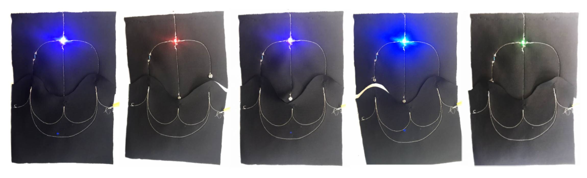
Final prototype
Here is the final prototype and the different colour options it made.
Making my own sensor
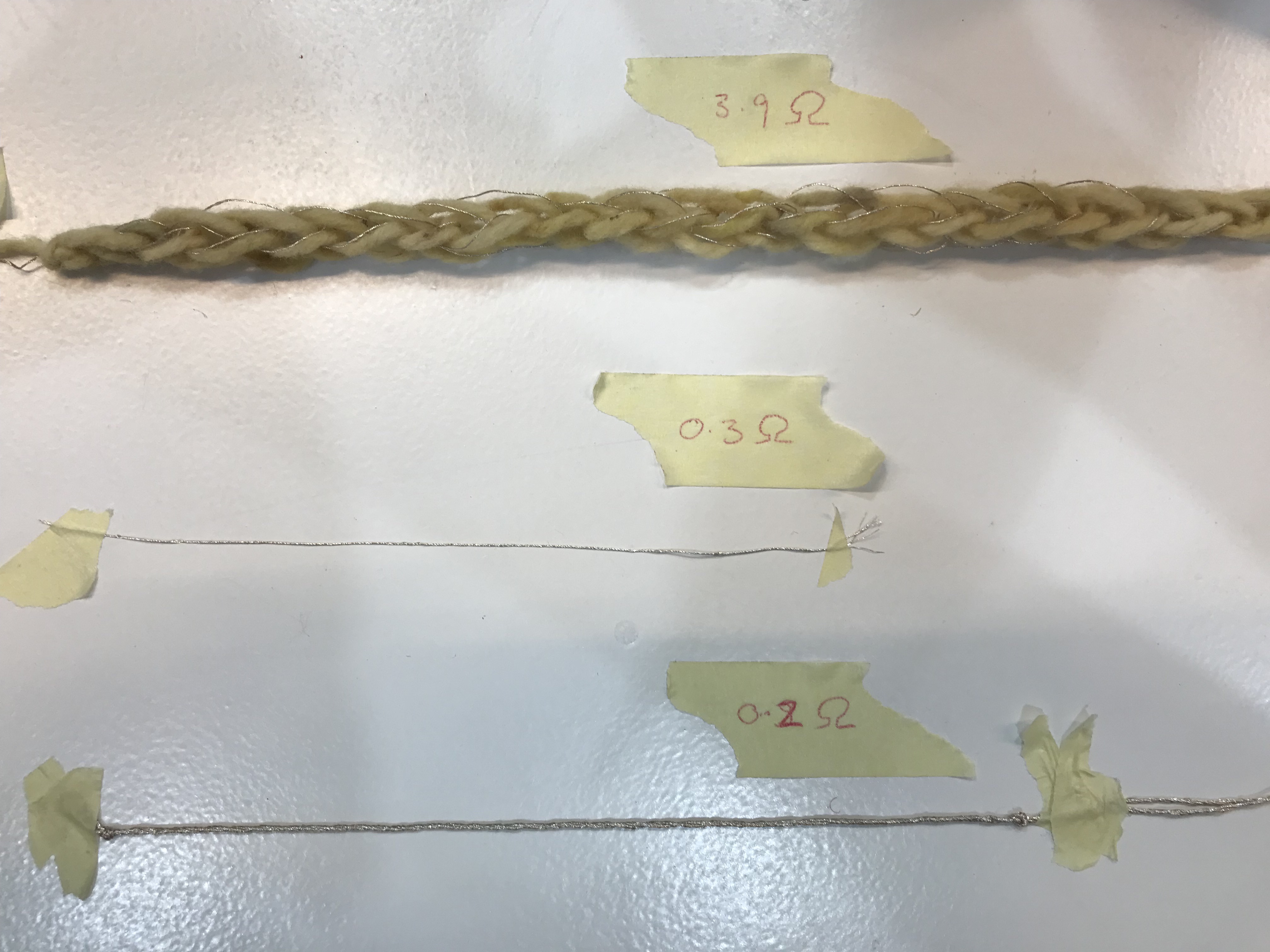
Experimenting with material properties
I wasn’t really sure what kind of sensor I wanted to make but I did want to try something quite different to the switch. So, to start I began by trying to understand the conductive properties of the materials we had and how I could change them, temporarily and permanently. For example, I looked at the conductive thread and how I could change the resistance of this. I tried first by spinning 8 stands of it together into one rope that had a slightly lower resistance than a single strand but only slightly. Then I tested the knitted samples I had made for the tube switch above, this had a much higher resistance than just the thread.
Combining materials
After this, I decided to try a few different crochet samples with the conductive thread and different materials to see how this changed the resistance. I made sample with a thick rope, 2 stands of conductive thread and cotton thread. These did all have slightly different resistances but as they only had very limited stretch in them based on how loose the crochet was done, they weren’t much use for a sensor as there wasn’t much change to sense.

Final Idea Process
Initial prototypes
Next, I made a few different sample with some conductive yarn so this had a lot of stretch in it that changed the resistance a lot. I wanted to see from these how the tightness of the knit/crochet and the shape would affect the sensitivity of the possible sensor. I found that the larger and tighter the knit sample, the less the resistance changed as it couldn’t be stretched as much.
yarn testing from Ruby Lennox on Vimeo.
Once I knew that the samples could produce different readings, I needed to work out how to what circuit to make and how to link it to the XIAO. I decided to keep the circuit simple and just made it so that the changes in readings from the knit changed the brightness of an LED. The actual circuit for this was fairly simple, but I did struggle initially with connecting the XIAO and the code I needed. I used the example LED Dimmer code from DeepBlue as a base and tried a few different values to see which worked best with the sensitivity of my sensor.

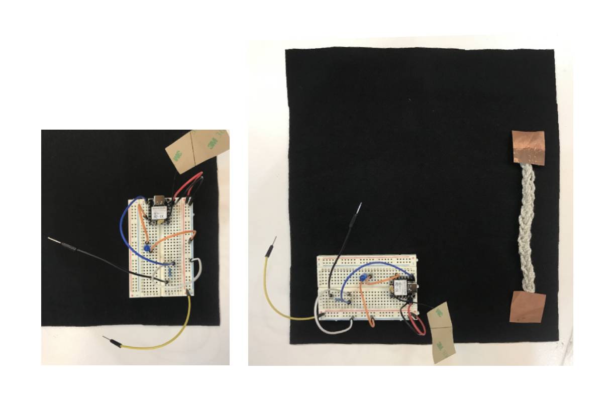
Final prototype
This is the final circuit connections shown on the breadboard and the textile sample construction.
final sensor from Ruby Lennox on Vimeo.
And the code I used in Arduino:
const int led = D5;

void setup() {
  // put your setup code here, to run once:
  Serial.begin(9600);
  pinMode(led, OUTPUT);
}
void loop() {
  int y1 = analogRead(A0);
  Serial.println(y1);
  delay(100);
  analogWrite(led, (analogRead(A0) >> 2));
}