Inspirations
As a new student in this domain, I think it might be worth mentioning a couple of open source websites that really helped me when I was learning about electronics. Kobakant - how to get what you want, for short and simple examples of circuits and codes, as well as soft components. Instructables, for cute open source projects in any field. Arduino - Project hub, for projects, examples and problem solving too!
Heat Pad
For the circuit, I used the tutorial made by Liza Stark. A heating element requires a lot of current, more than what an arduino can provide. To work proprely, The circuit needs to include another power source.
Actuator
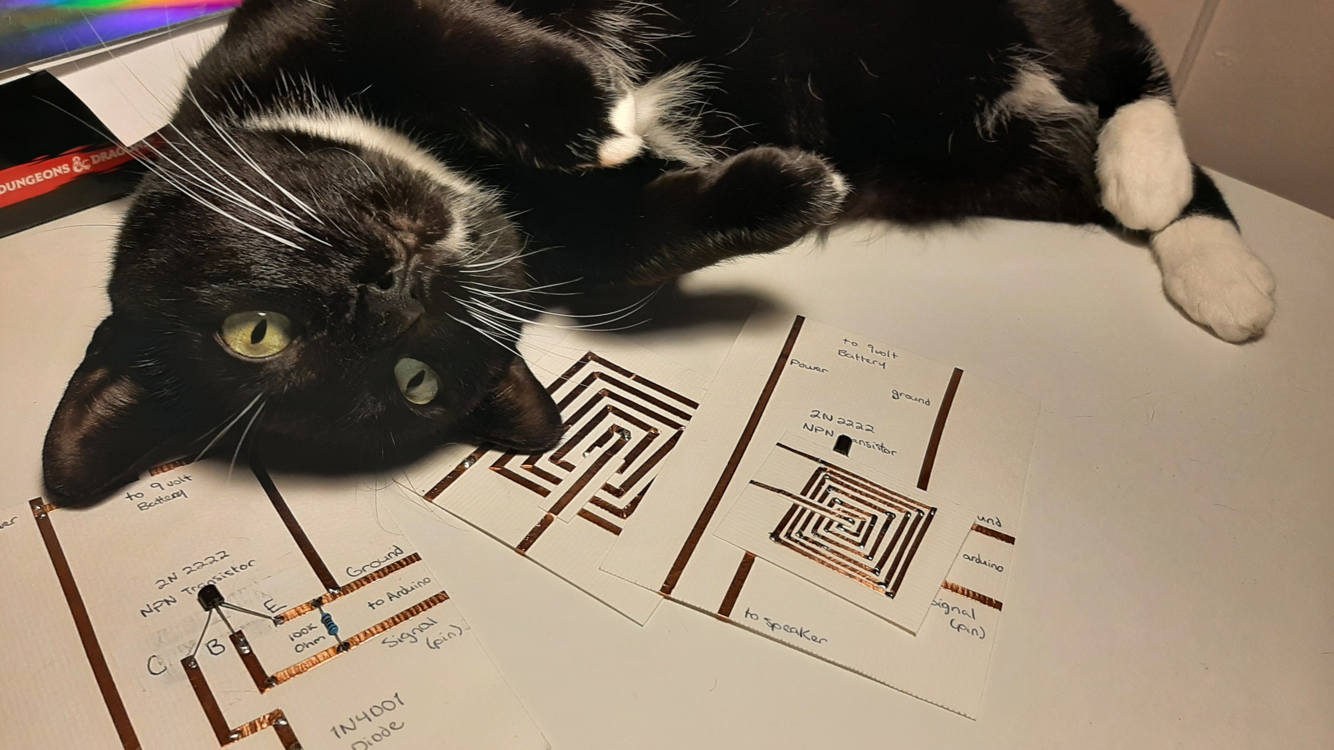
An actuator is a component in a circuit that allows us to control our element based on an input. the most important component here is the black element in the middle of my sample, that is called a transistor. Transistor are used like an electrical switch. It allows us to control the circuit with the arduino. If we provide a little bit of current from the arduino, it will allow the current from the battery to go trough too.
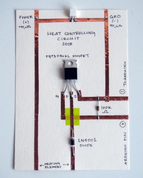
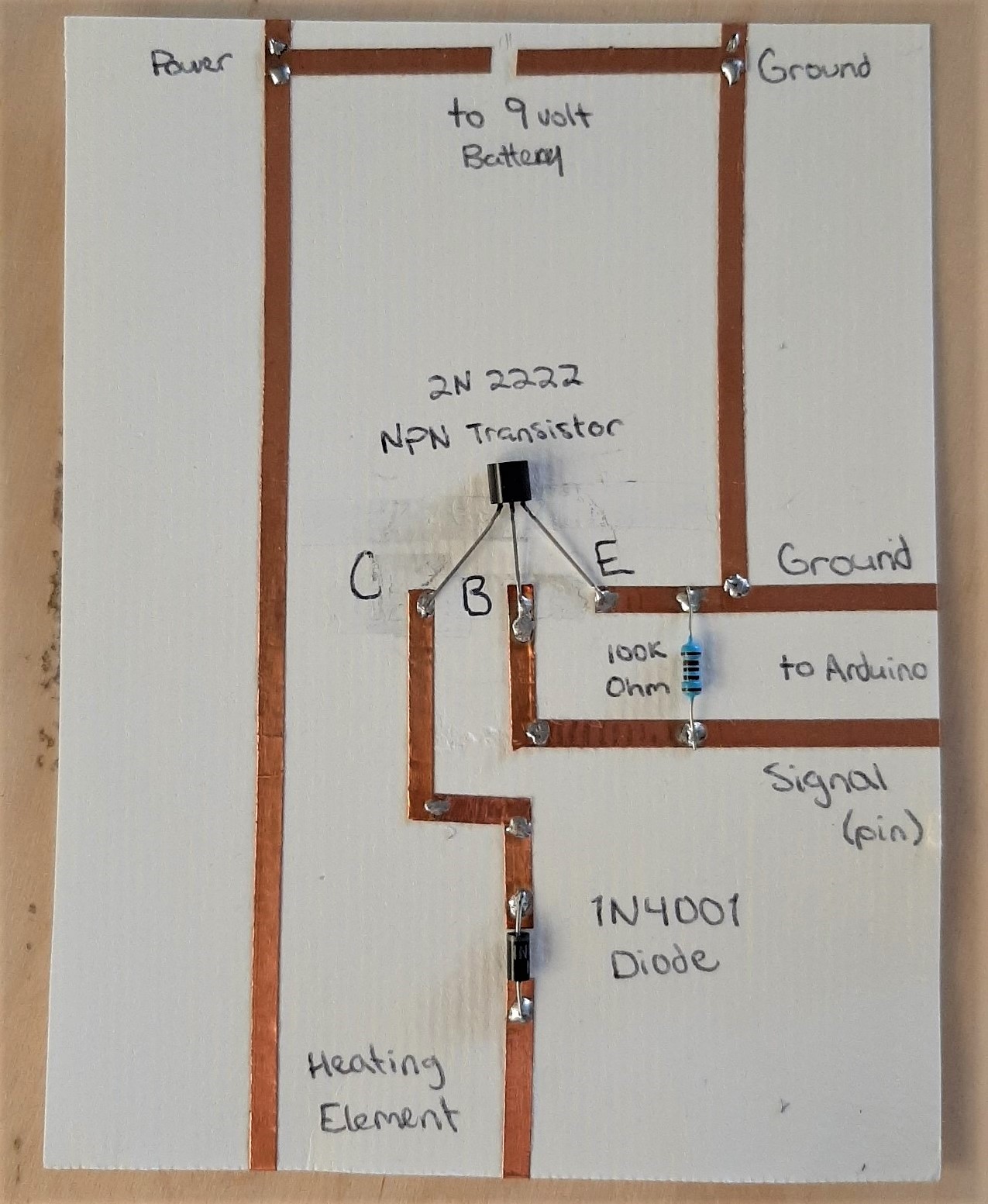
In the example, MOSFET transistors are used. BJT transistors are what I had available at the lab, so I had to adapt the circuit a bit. Each transistor type has adventages and disadventages. For those of you who struggle choosing the right transistor for your project, I would recommend this website. In short, MOSFET can sustain more power without overheating, but are also a bit more expensive.
To better understand how I adapted the circuit, we first have to understand how these two work. In the case of a MOSFET, the current will go from the Drain to the Source, depending on the input from the Gate. The BJTs work almost the same, but the terms are different. in the case of a BJT, the current will go from the Collector to the Emitter, depending on the input from the Base. on the left, you can see the circuit as it would have been with a MOSFET, and on the right, how I changed it.
Engraving Tests
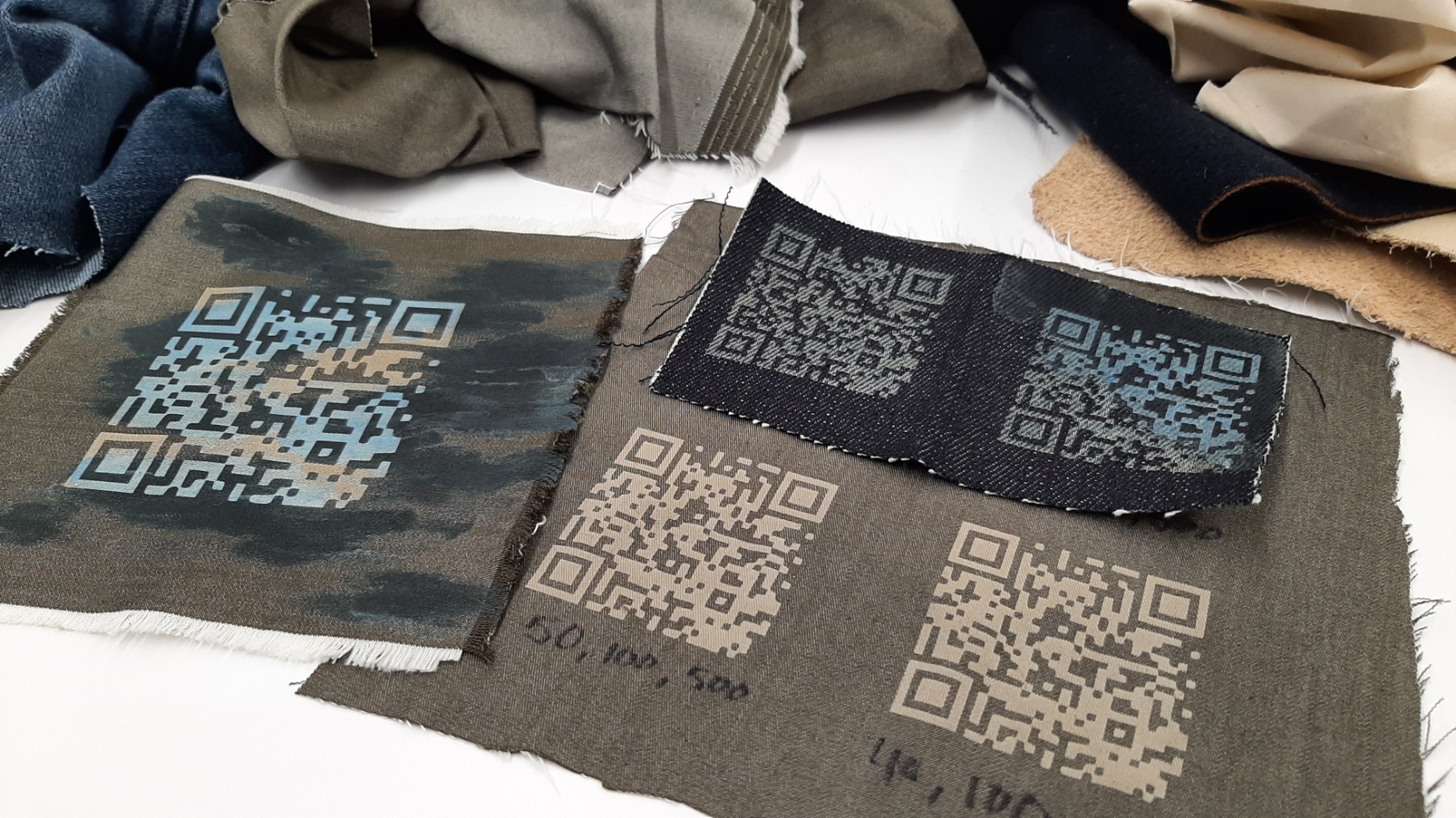
 I wanted to try something special with the thermochromic ink. I started by making some tests with the laser cutter on materials like denim. The fancy thing about denim, and why they look so good when they are used, is that they are weaved with two different colors. The blue, almost black, is the color we see when the denim is new, but underneath, the tread is white. So when we laser cut on denim, what was engraved now apears white. The same is true for any fabric that is made like denim, with one color on top, and another one underneath. I tried with denim from an old pair of jeans, but the result wasn't as good. Since we buy jeans pre-bleached, the white engraving just didn't stand out as much.
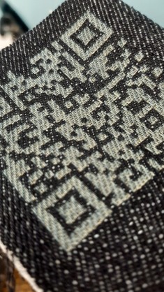
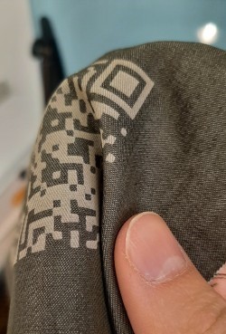 Engraving on non-stretchy and non-bleached denim did wonders! I took note of the parameters of the machine, but they will change a lot depending on the fabric. Watch out, if you engrave too much, the fabric will break! make sure to test the solidity of the result before engraving a big drawing. The green sample you see is a light fabric I used to make a shirt, that had a warp thread a different color from the weft thread. You can also see the effect of laser engraving on thermochromic paint: black when cold, blue when hot. The denim was too dark for the blue to really pop.
The Fish
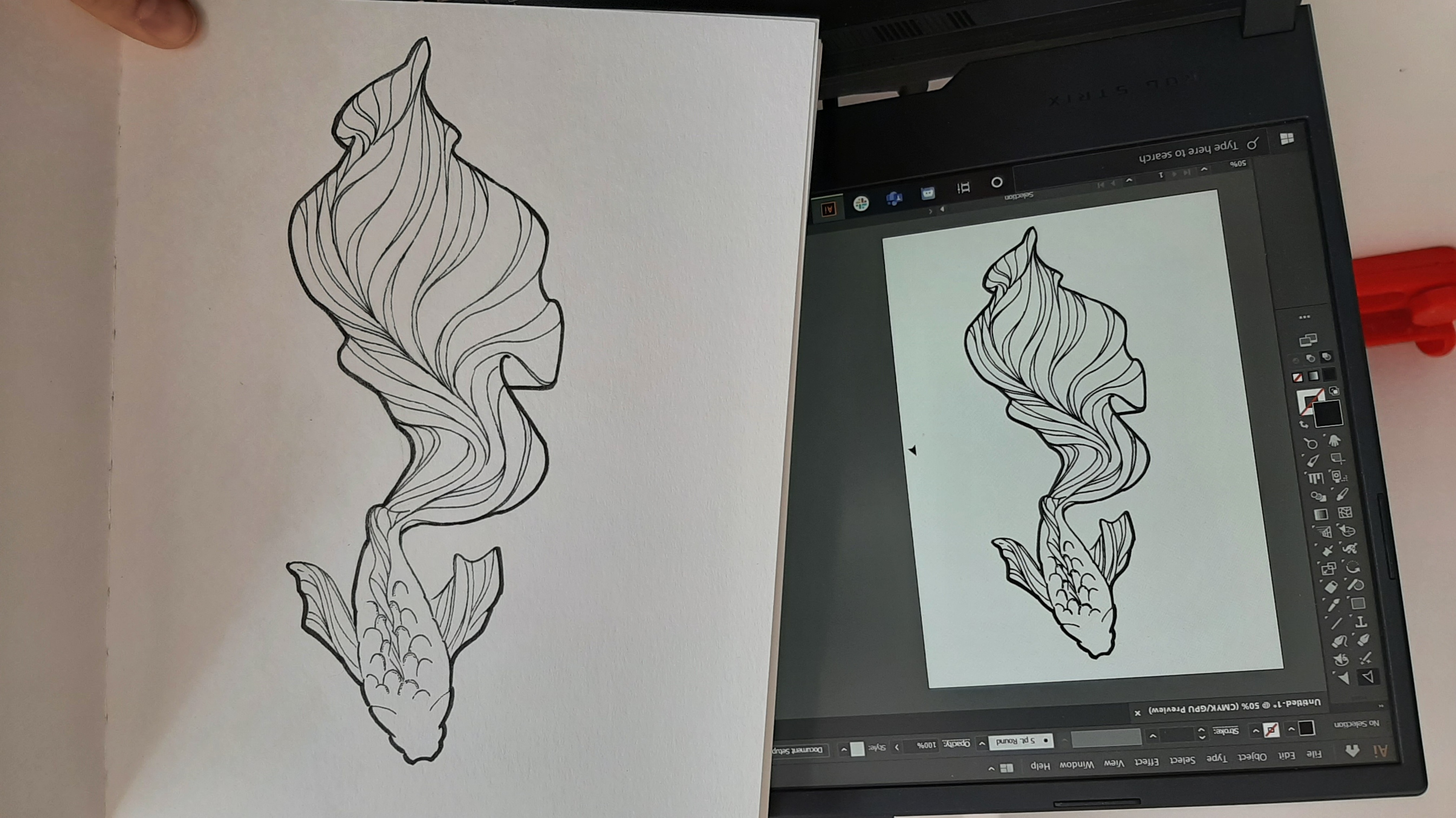
I imagined a design that would be nice to print in colorchanging paint. Now that I knew that engraved, the paint I have will turn light blue, I designed a fish, hand drawn on paper, then digitalised it to play with it (vectorizing a picture with illustrator). The drawing will be available at the end of this page ;)
Screenprint
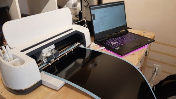
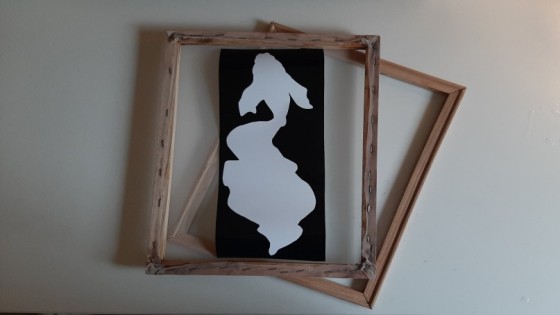
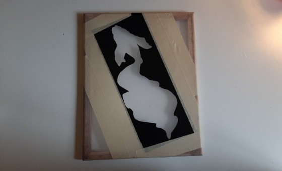
My first step would be to make a print with the paint. To do so, I vectorized my drawing, and used only the outline of the fish for the print. I used my cricut to create the template. I removed the part with the fish, because this is where I want the paint to go.
Remember that frame? I used it for the biomaterial week to create paper! What a practical little thing from the dollar store!
To stick the template to the frame, you have to remember to stick it to the side that will be in contact with the fabric, so you can scrape without having to worry. I used tape to cover the rest of the surface, to protect the fabic from the exedent of paint.
Note that this method is like a cheap way to do screenprinting. It's okay in my case since it's a big shape, but small pieces might not stick to your frame, and details will be lost.
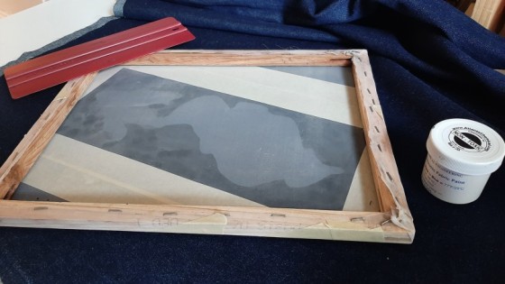
When applying the paint, I first passed one time pressing hard, to make sure the paint goes everywhere and fills all the cracks. I then pressed more lightly, to make sure there would be a relatively thick layer of paint. Don't forget to keep the exedent of paint! Once everything was dried, I ironed it (some screenprinting materials require this step for the material to really stay on the fabric).
You prefer to put too much paint, and collect it afterwards, to apply your first layer in only one go. Do not move the frame once you started scrapping, and do not try to put in back in place if you mess up!
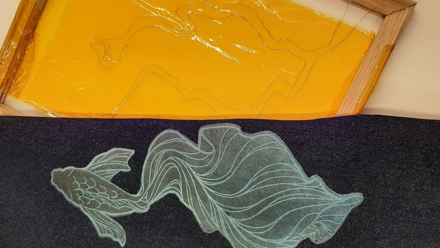
Laser Engraving
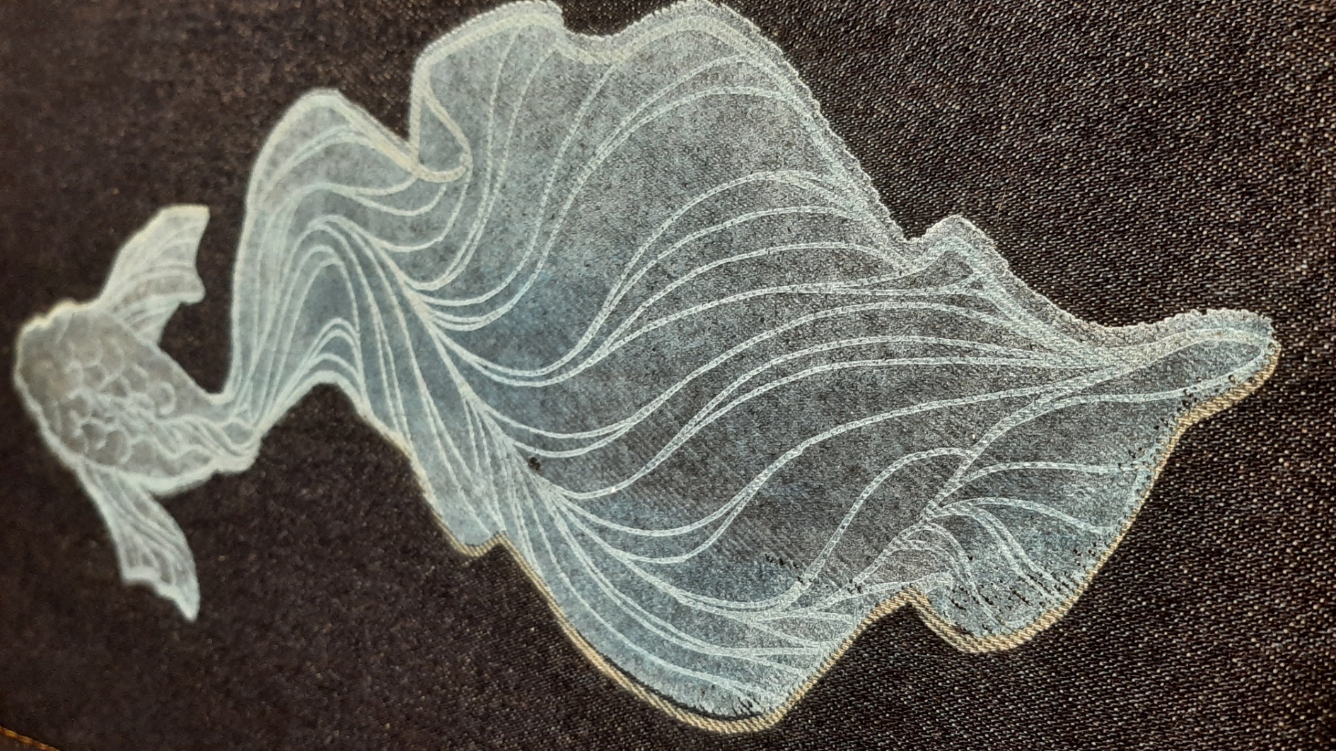
Luckily, the paint is non-toxic, and turns light blue when engraved. The results were breathtaking!
The most difficult part was to place the screen printed fish on the fabric exaclty alligned with the one that was about to be engraved. With the help of the preview directly in JobControl (the software we use with our laser cutting machine) I alligned some key points the best I could. I made sure that the files of my two prints were exaclty the same size, so I would only have to worry about the allignment. I still got minor problems, a shift of about 3mm.
Make sure to lay the fabric as flat as possible, so it doesn't get in the way of the machine and catch fire.
Every fabric is different, so do a lot of tests before going with a final version!
Circuit
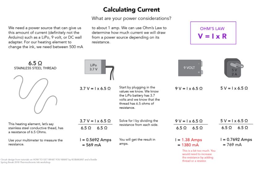
In our case, to heat the thermochromic ink, we will need between 500 mA to about 1 amp. I kept in mind, when I made the circuit, that I wanted about 9 ohms of resistance, but I also know that my paint switches color at 25° celcius, so it won't need a lot of heat to switch color.
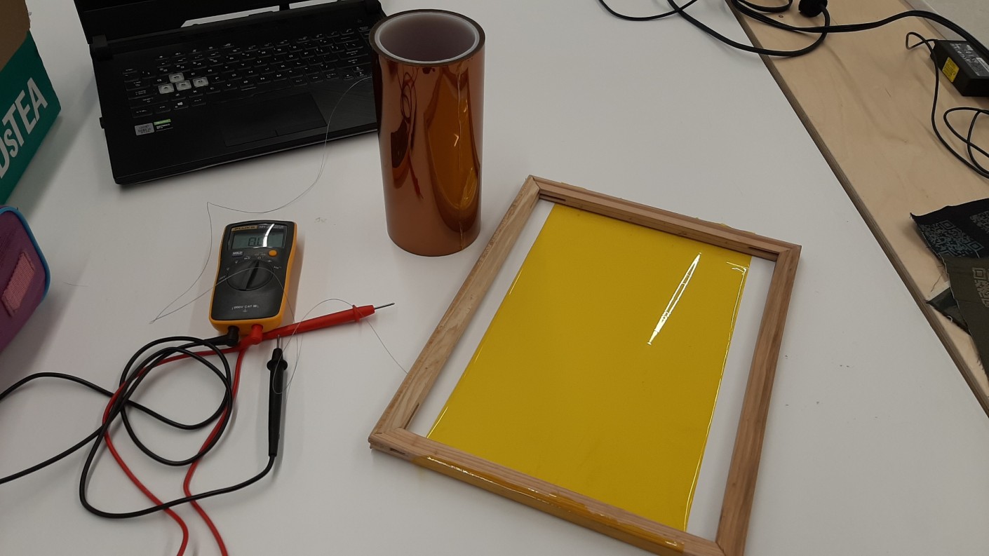
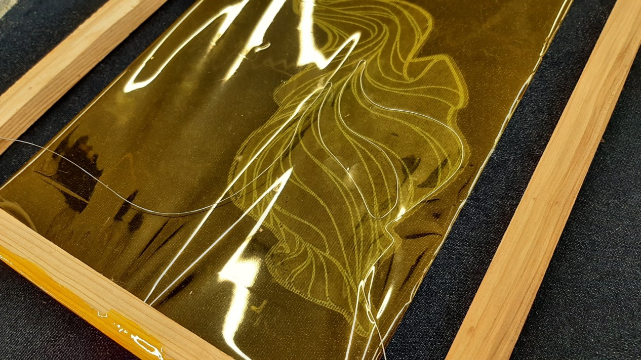
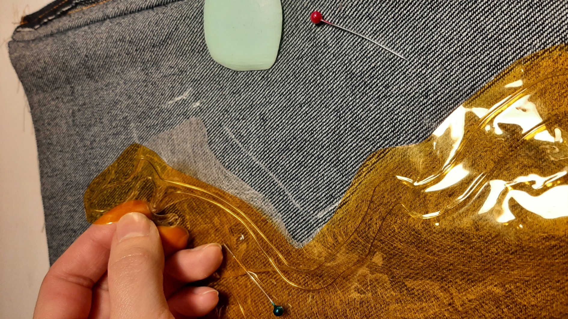
I stated with the insolating material, a yellow tape used to protect the circuit, but also the wearer. It's called Kapton tape, and is a material well known for its temperature stability and its electrical isolation ability. Since a heating element, with a lot a ampers and volts, can be pretty dangerous, a protaction is necessairy. I streached it on a emplty frame, to place it over my fish while working. I was then able to choose where the fish would heat first, depending on where I placed my circuit. I made sure not to create any short, by keeping the tread from touching itself.
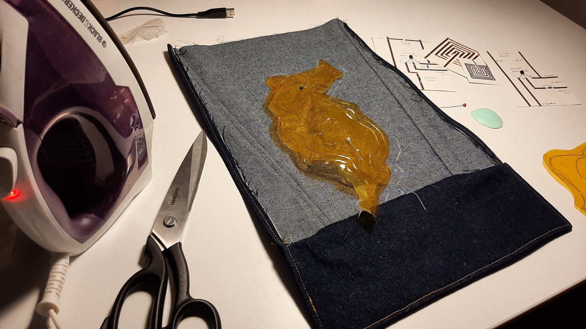
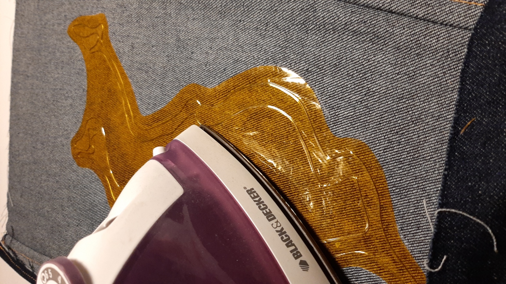
Once my circuit was fixed between two layers of insulated tape, I got the result out of the frame. My new heat pad was fully fonctionnal! I used a heat and bond material, some very thin material that melts under an iron, and is used as glue. I made sure to mark the emplacement of the drawing, by sticking a needle in a key element of the drawing and marking it on the other side with a white soap. The drawing had to be alligned for the heat to be exaclty where I planned it to be.
I mannaged to fix it with an iron, but a heat press would have worked too. I was worried that it could detatch with the heat of the circuit, but I didn't have any problems at all. The result was a bit stiff, but looked really porfessional.
Copper Tape & Vinyl
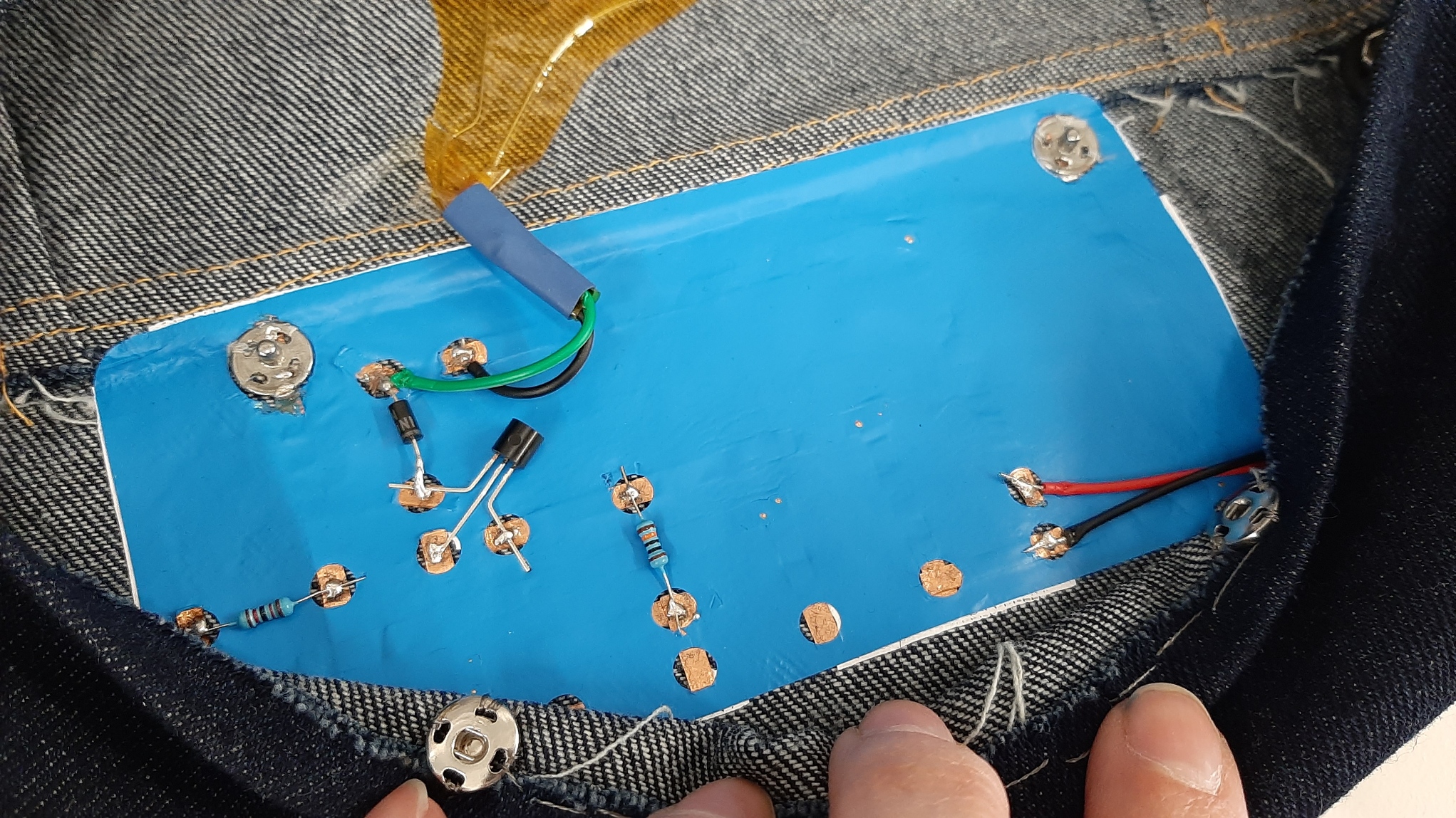
I started with a quick sketch of the circuit and the components. There are two main things going on in there: first the circuit for the heating element and it's external power source, and second a button with a pull up resistor. The circuit for the heating element is exaclty the same as the paper actuator I made earlier, you can learn all about it in Liza's tutorial. The pull up resistor button circuit I used is exactly the same as I used in the E-textiles week, and is better explained in this page.
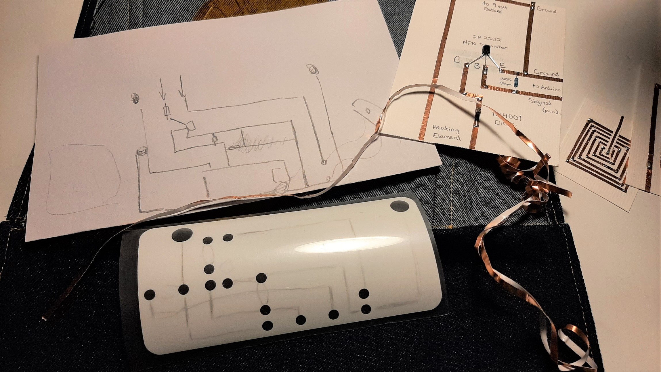
I wanted to use copper tape, since it's so easy and quick to fix. For more solidity and durability, I used vinyl. I prepared my file according to my plan: everywhere I knew I would need to sloder an element, I made a hole in the vinyl (the final svg file is available for download) It was the perfect solution to protect the circuit and still see all the elements, to fix any broken part or problem along the way. I cutted everything with the cricut.
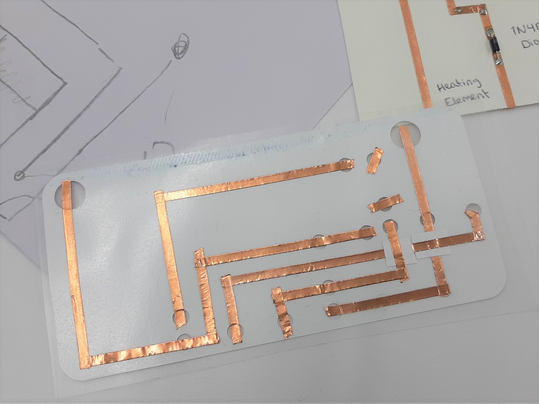
I failed my first attempt (white). I forgot to peel the vinyl out of one little circle, got mixed up in the circuit. I also forgot to solder together all the corners of my circuit: every time I cut the tape, I was supposed to solder the edges together. I peeled my mistake the best I could off the denim.
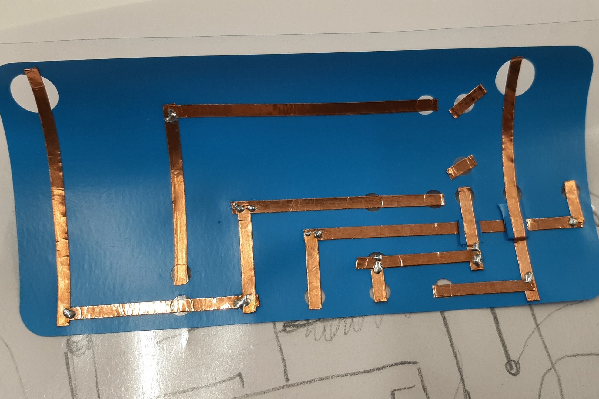
My second attempt was perfect. You can see the circuit before I stick it to my sample. This time, I made sure there was current passing everywhere I needed it.
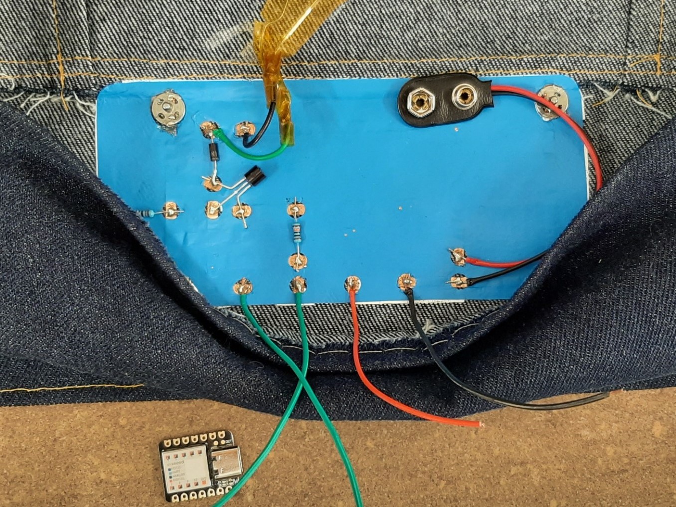
Fixing the Elements
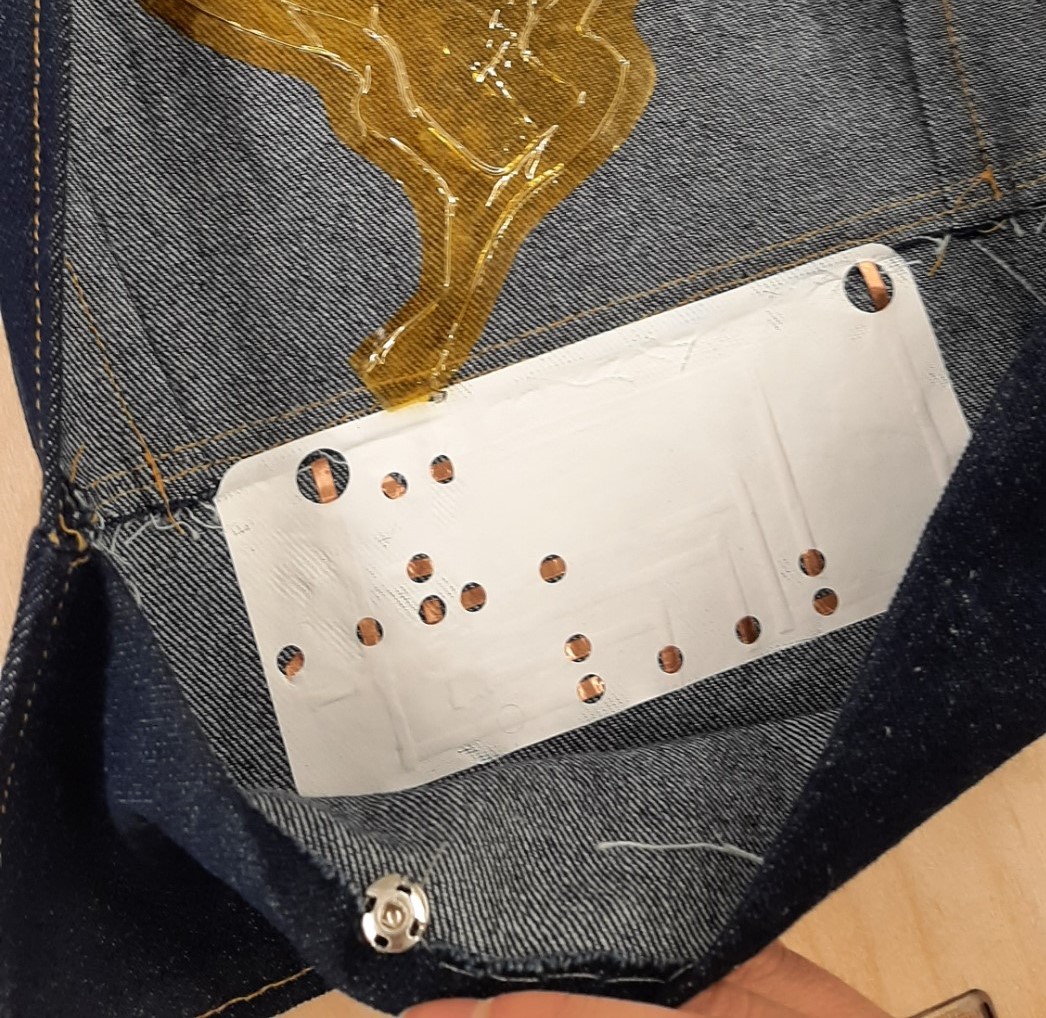
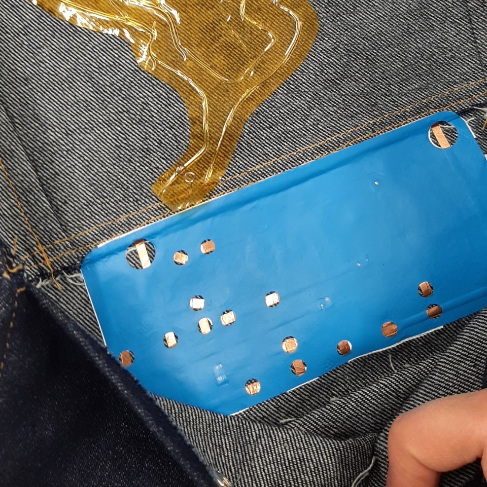
I started with the snaps, and sew a conductive wire between both of them, on the layer of fabric where my circuit wasn't. The idea is that when both snaps are closed, the current will go trough, and the "button" will be pressed. I then soldered everything to the copper tape, even the snaps. The glue underneath the tape was pushing away the tin, making the soldering difficult. I made sure to cover the two wires of the heating element, to protect the circuit against a short. I had a lot of problems with the wires that were connected directly to the seeduino, they broke easily. Other than that, the connections were impressively stable! I am so proud of the result! So thin and flexible!
Code
The code was the hardest part for me... I simply followed the examples mentioned earlier, and put them together as I thought made sense. I was lucky François was near. He doublechecked my code when I couldn't find why it wasn't working, and expalined to me the lines of code I didn't understand at first.
const int heatPad = 2;
const int buttonPin = 4;

int buttonState = 0;

void setup(void) {
  pinMode(heatPad, OUTPUT);
  pinMode(buttonPin, INPUT_PULLUP);
  Serial.begin(9600);
}

void loop(void) {
  //put your main code here, to run repeatedly:

  // read the state of the pushbutton value:
  buttonState = digitalRead(buttonPin);

  //check if the pushbutton is pressed. If it is, the buttonState is HIGH
  if (buttonState == LOW)
  {
  //Turn the secondary power source here, to run repeatedly:
  digitalWrite(2, HIGH);
  Serial.println("ON");
  //Change the delay to keep the heat longer
  delay(100);
  }

  else {
    digitalWrite(2,LOW);
    Serial.println("OFF");

  delay(100);
  }
  Serial.println(buttonState);
  delay(1);
}
Result
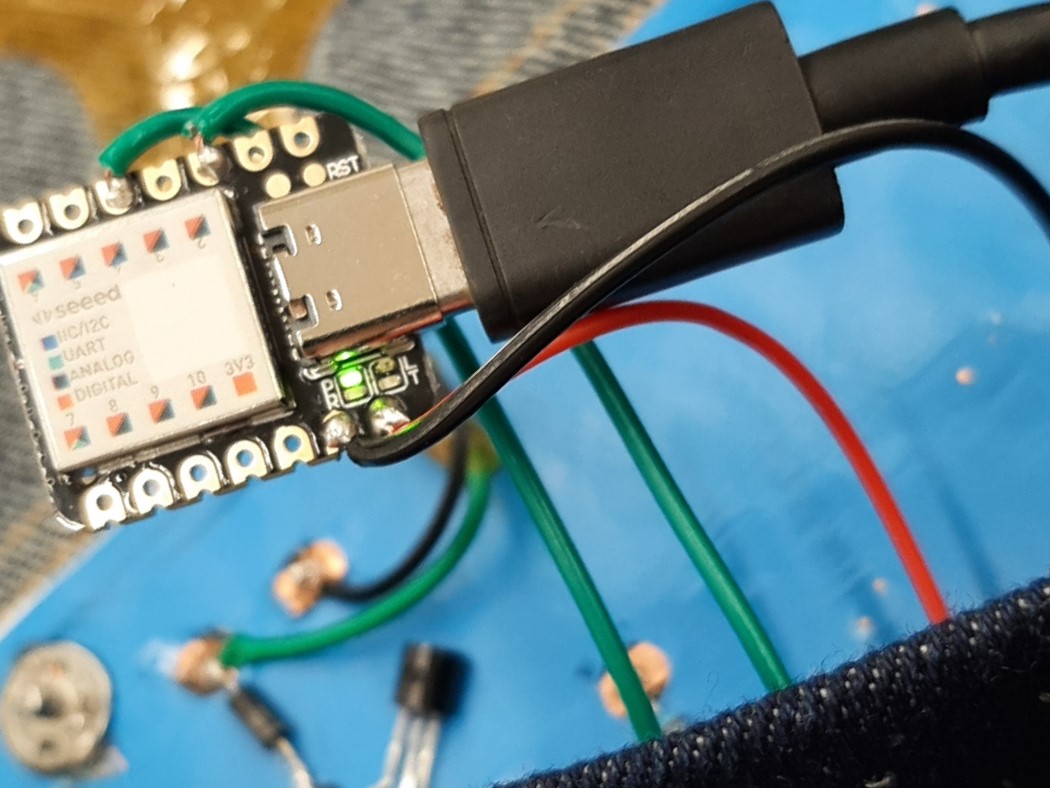
Overall, the heating element is "on" when the two snaps are closed. When one or both are open, the circuit turns off. The heating element is powered by a 9 volt battery. for the sake of the example though, I plugged it to a 12 volt power source (that I started manually once the swatch was right side up). The seeeduino controls the circuit, and needs to be powered by an external battery, but is plugged to my computer in the video so I can see what's happening.
Speakers
Speakers are made of an electro magnet, a magnet and a diaphragm. In short, Sound is created by the movement of the electromagnet against the magnet. If you are interested on the topic, I would recommend you to take a look at this website for a more complete explaination on speakers.
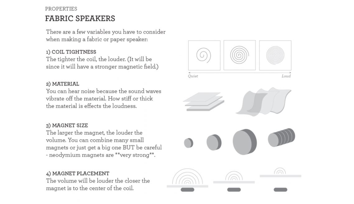
In other words, we want to create an electromagnet. It can be of any shape, any thickness we want. There are a lot of things to keep in mind while we disign it tough. Soft speakers are a lot less loud than hard speakers. Idealy, the sound is better when the diaphragm is thin, tensed, and do not let air trough. Here is a more complete list from Liza, of all the properties that can affect the sound and the effectiveness of our soft speaker. For the optimal sound, we would have to take the optimal parameters.
Actuator
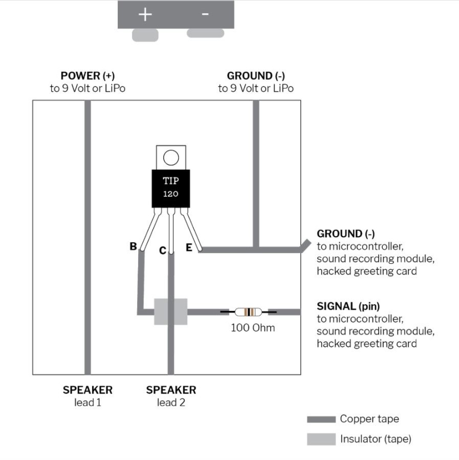
An actuator is needed to control the speaker. This time, I used the example of speaker by Liza Stark. I adapted the circuit to the 2N 2222 NPN transistor I had.
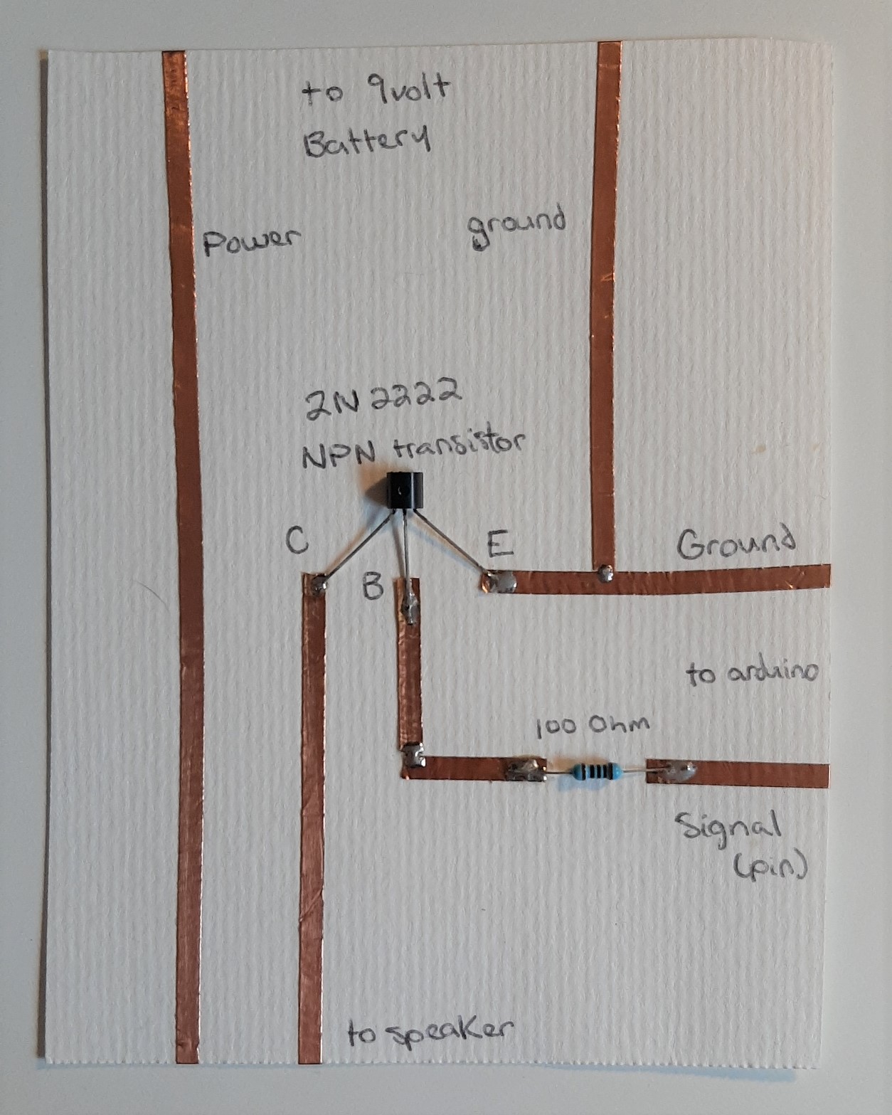
Speaker
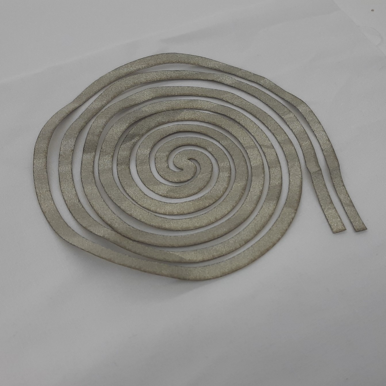
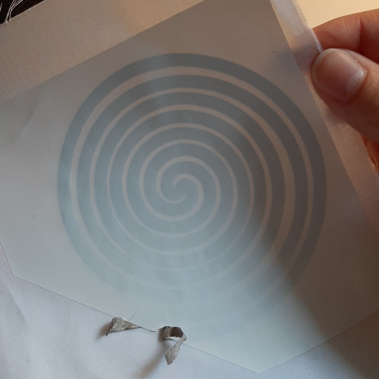
This prototype is made of woven conductive fabric. I made a spiral in inkscape, then cut on the conductive material. I used laser for the cut, but the cricut machine would have made a better job, without the burnt edges. I covered and fixed the circuit with vinyl, making sure that nothing was touching each other. It was really hard to place it precisely, so I couln't make a smaller one, even if I wanted to.
Tests
I started by connecting everything to the actuator. In this example, I used the 5.5v output of the arduino as a battery. I looked for a simple code I could use with the arduino (link to download at the botton of this page). You cannot give a mp3 to an arduino, unless you have an external sd card for more space. No worries, I will be able to plug my speaker directly to my phone later, with the mono amp. For now, there will be only notes, and a robotic melody. Once a made sure that my connections were okay, I plugged my cardboard and copper tape speaker. The second one, my fabric speaker, was a lot more faint. (the audio might be bad in the videos).
Mono Amp
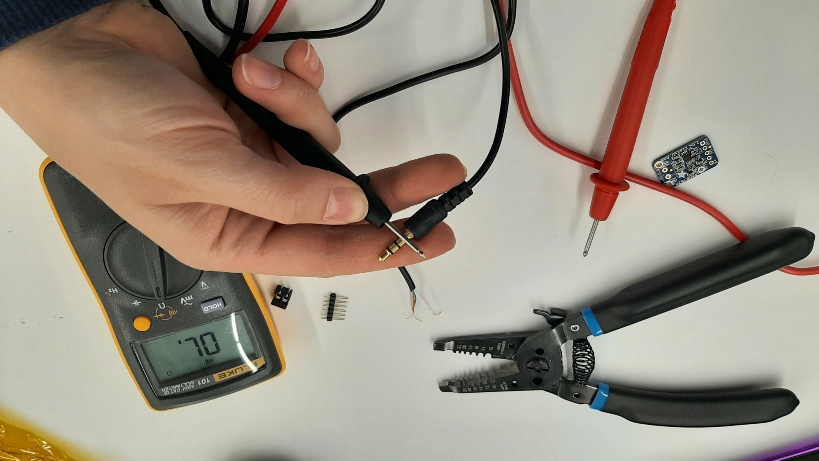
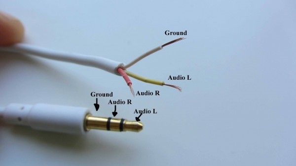
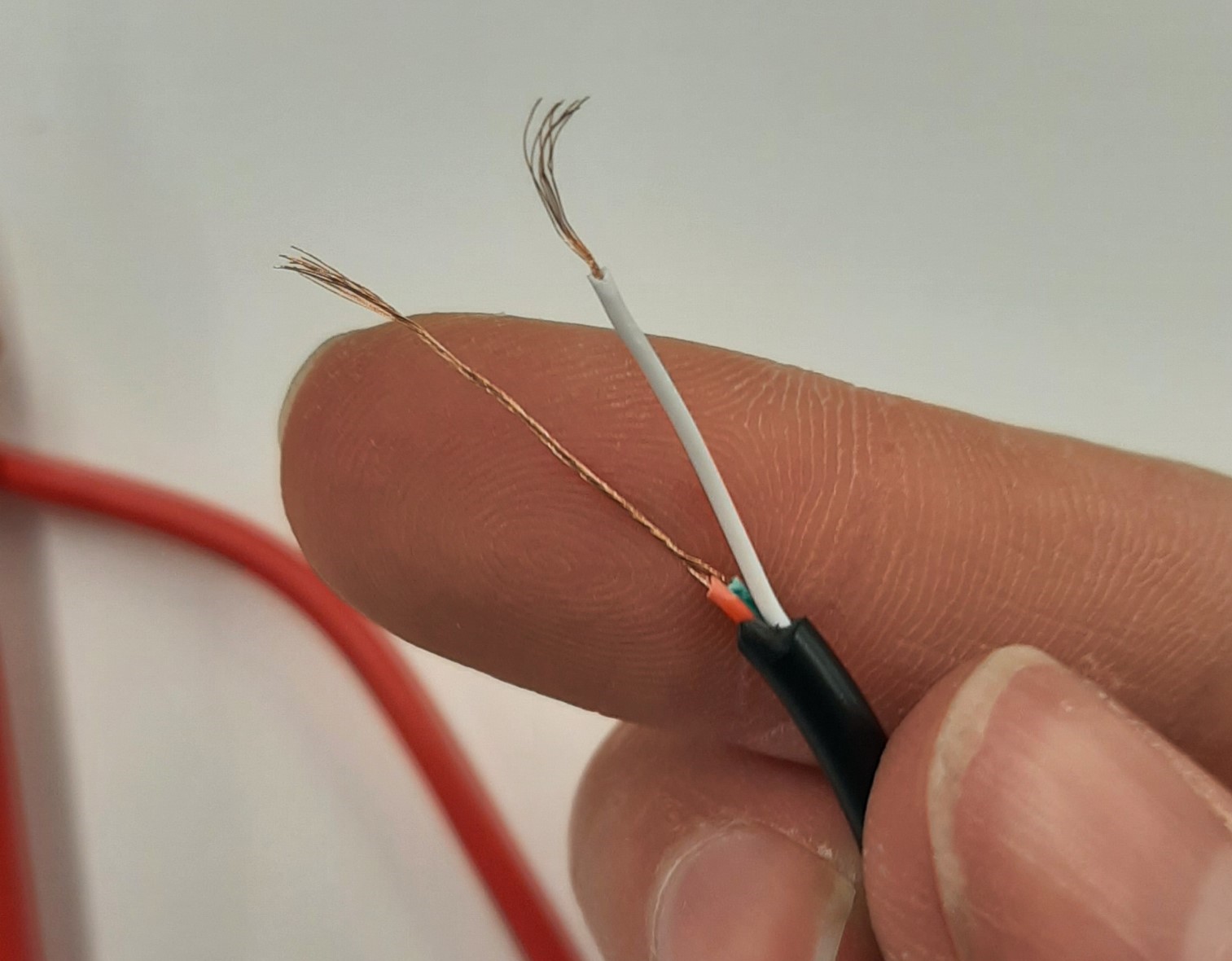
I bought my own mono amplifier from Adafruit. I was able to follow all the steps of Liza's totorial on how to make a custom mono amp for soft speakers. I would recommend to take a look at her tutorial of you plan on making soft speakers. The only thing I had trouble understanding, is how to connect my audio cable. I bought a stereo audio cabple from the dollarstore. When I opened it, the colors of the wires were not the same as in Liza's exemple. The trick was to probe, with a multimeter, each wires and parts of the audio cable to identify the ground. once that was done, I mixed together the left and right of the stereo to create a mono.
Unfortunatly, I haven't made it work yet. By plugging it directly in my phone as instructed, and then to each wire of the speaker, it didn't give any output. There can be a lot of various reasons why it didn't work. Stay tuned for updates! If I make it work eventually, I'll add it to this webpage.