5. E-textiles
Research
For this week’s assignment we learned about how we can produce soft circuits, sensors, actuators and build at least one digital and one analogue soft sensor, using different materials and techniques.
But first of all some basics about electricity:
basics
There is a lot of different kinds of energy around/ in us:
mechanical energy
- cause : motion
- result: motion
thermal energy
- cause : different heat
- result: motion, heat
sonic energy:
- cause : vibration
electrical energy
- cause: charged particles
- result: motion, heat, sound, light.
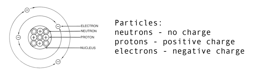
electrical energy:
A form of energy resulting from the existence of charged particles
In an atom, the core holds protons and neutrons together, while electrons are orbitting around them:
+ and - are attracted to eachother
When we force electrons to group in a certain area, leaving another area without electrons, we create a difference in voltage. This voltage is the relationship between the energy we applied and the electric charge:
Voltage and current:

We measure electricity in voltage (volts: V) and current in AMPS (A) a famous example to understand this relationship is the waterfall. The volt represent the pressure built up by the water mass on the top of the mountain and the current is the rate the water can flow decided by the size of the stream.
circuit:
A circuit is a CLOSE LOOP in which electrons can travel in a by us controlled environment.
Electrons always move from POWER (VCC+) to GROUND (GRND –), they always take the shortest ways possible
 drawing
 sample
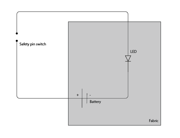
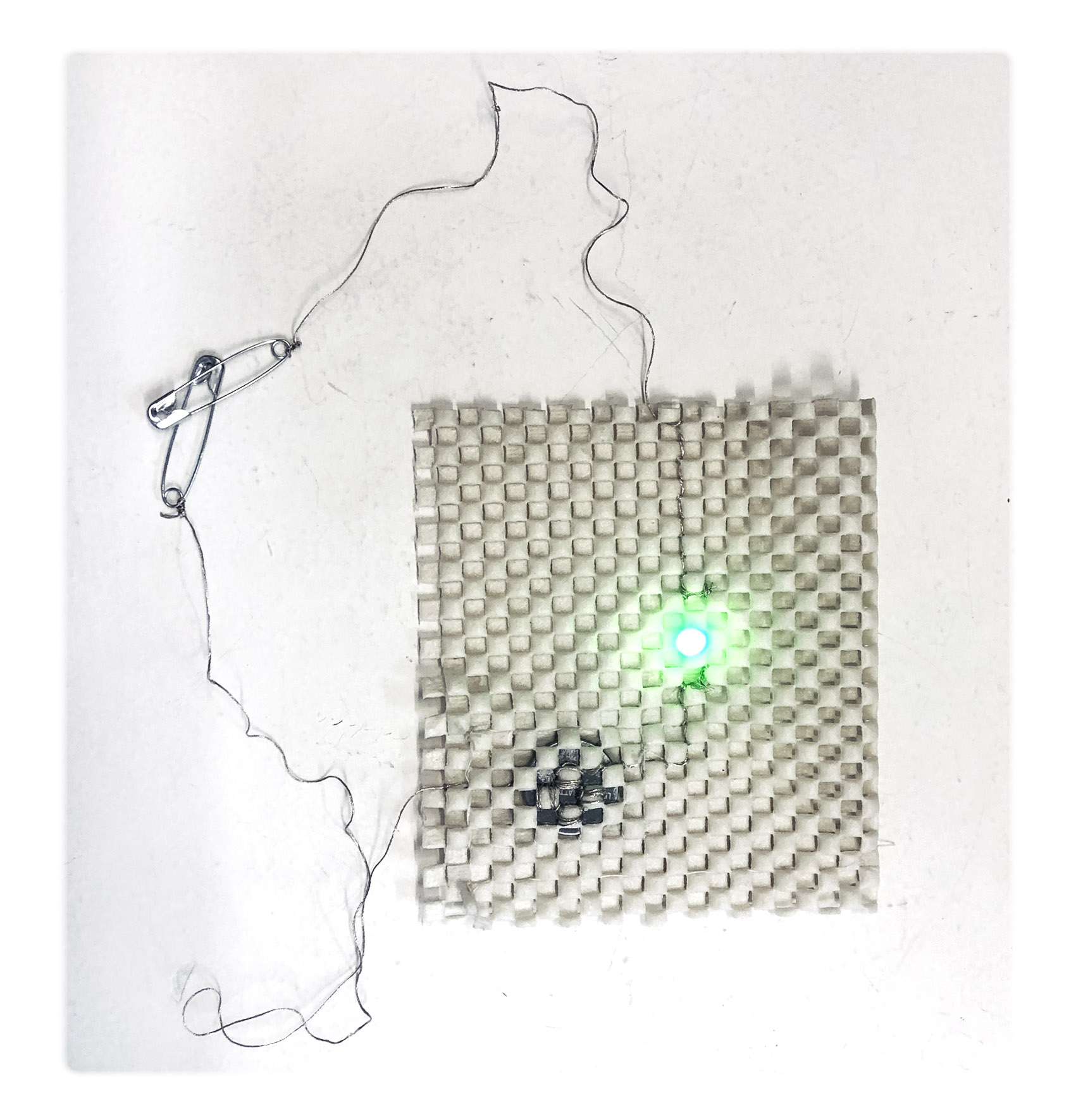
Example of a basic soft circuit using fabric mesh, conductive thread, coin battery and 2 safety pins. We can use this circuit to test conductivity of different materials
What do you need:
- source of electrons: POWER SOURCE
- material to let the electrons flow: TRACES
- Circuit path for electricity to move
resistor_
For the battery not to overheat (short circuit) we always need to use all the electricity in the circuit. For example if the LED is not using all the current we need to use a resistor to control the current (not overflowing the waterfall)
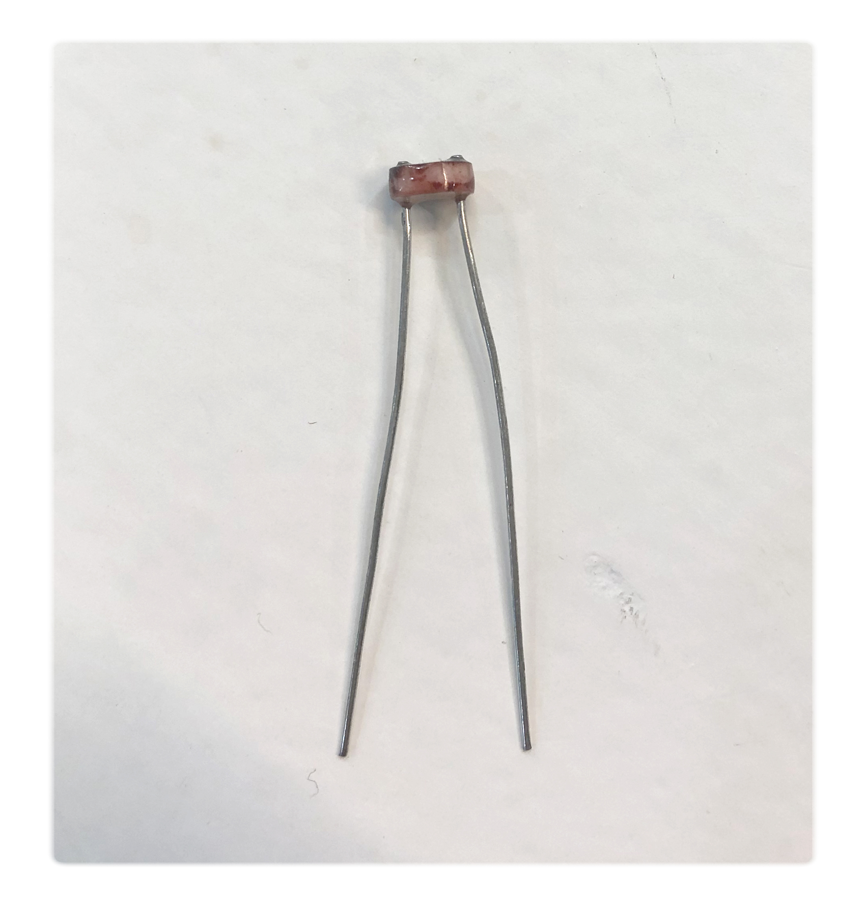
Their is many kinds of resistors, but at its core its basically two wires or conductors attached at opposite ends or sides of a relatively poor electrical conductor.
See more info about sizes and color codes for resistors:
To know which (if any) resistor we need to calculate how much power we are using in the circuit this we do with:
ohms law
Ohm’s Law defines the relation between voltage,
current and resistor:
You know the Voltage and the Resistor =>
=> calculate the current you consume: I = V / R
You know the Voltage and the Current =>
=> calculate the resistor you need: R = V / I
We can use this online calculator to do that:
https://ohmslawcalculator.com/led-resistor-calculator
Voltage: is the difference in charge between two points.
Current: is the rate at which charge is flowing.
Resistance: is a material’s tendency to resist the flow of charge (current).
multimeter, how we mesure voltage, ampere and resistance
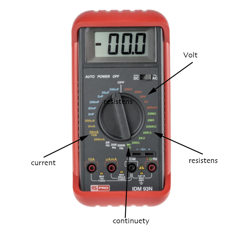 Use multimeter:
- select the right mode and range
- check if the the lead are in the right position
- touch the terminals of the battery with the two leads
conduciveness of a material: Use CONTINUITY MODE
resistance: Use Ohms scale
voltage: Use Voltage scale
current/ ampere: Use ampere scale
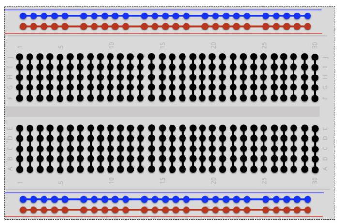
bread board
When we are prototyping new circuits, we always use a breadboard
to test out the connections before we start the fabrications.
The board is constructed so that you can connect different holes with each other, see drawing:
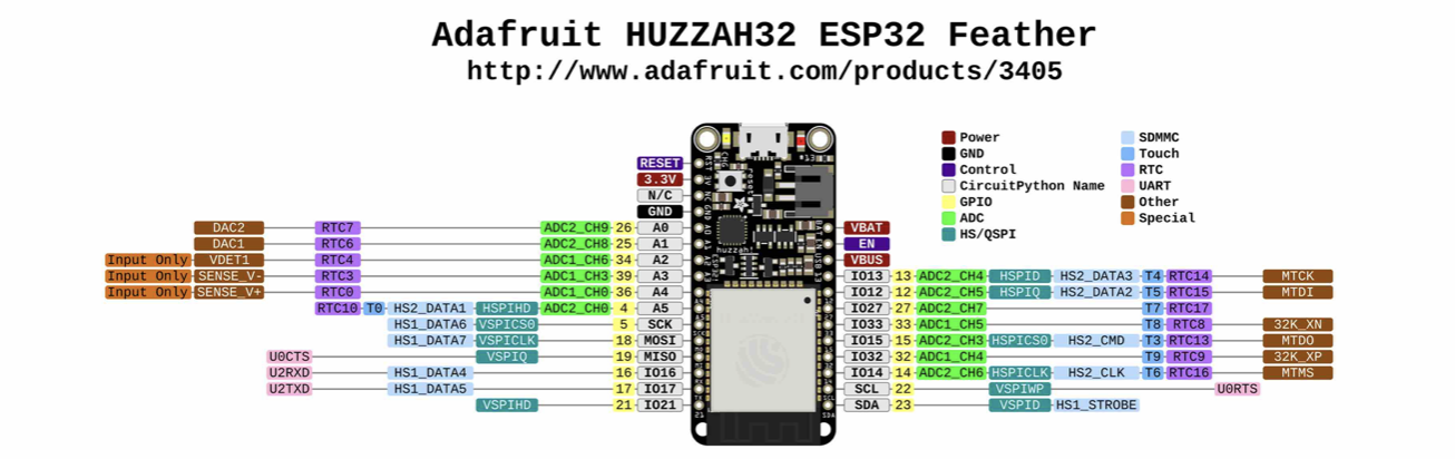
arduino
Arduino is an open-source electronics platform based on easy-to-use hardware and software. The Arduino boards (microcontroller) can read the signals (electric current) from our sensors, by giving the input data different meaning we can in the software code different output parameters.
For our project we used the Feather microcontroller (from Adafruit) instead of the Arduino board but configured it to the Arduino software.
This is example of most basic command for blinking light:
Digital output with digitalWrite() using delay function.
<br /><br />
void setup() {
  pinMode(13, OUTPUT);    // sets the digital pin 13 as output
}

void loop() {
  digitalWrite(13, HIGH); // sets the digital pin 13 on
  delay(1000);            // waits for a second
  digitalWrite(13, LOW);  // sets the digital pin 13 off
  delay(1000);            // waits for a second
}
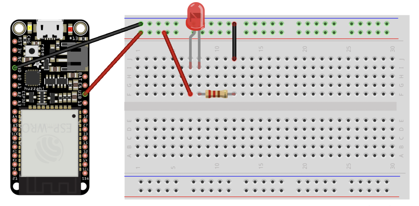 breadboard setup
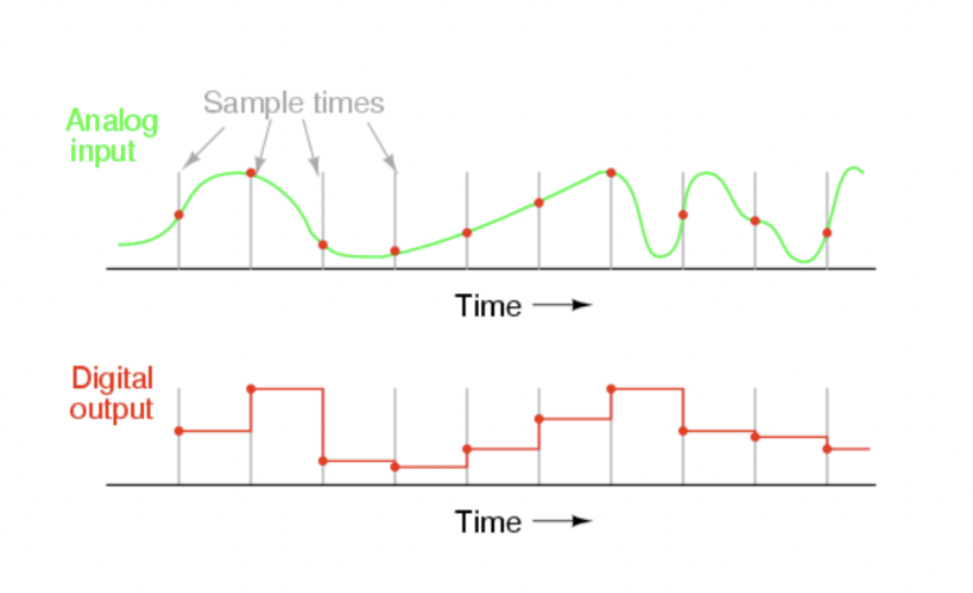
analog and digital:
A single switch can be on or off, enabling the storage of 1 bit of information. But in order for a computer to understand a scale of information for example from a pressure sensor we can group switches together that stores larger numbers. This is the key reason why the binary system is used in computer systems.
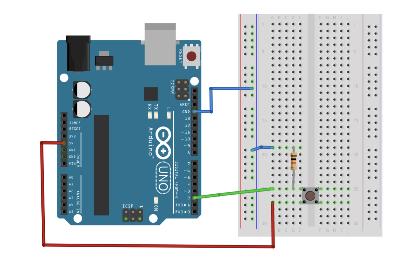
 Prototype for circuit with a swith control to turn on and off the light
Digital read:

int ledPin = 13;  // LED connected to digital pin 13
int inPin = 7;    // pushbutton connected to digital pin 7
int val = 0;      // variable to store the read value

void setup() {
  pinMode(ledPin, OUTPUT);  // sets the digital pin 13 as output
  pinMode(inPin, INPUT);    // sets the digital pin 7 as input
}

void loop() {
  val = digitalRead(inPin);   // read the input pin
  digitalWrite(ledPin, val);  // sets the LED to the button's value
}
 example of a simple on/off digital button
Example for reading an analog sensor using mapping to define the scale of input values
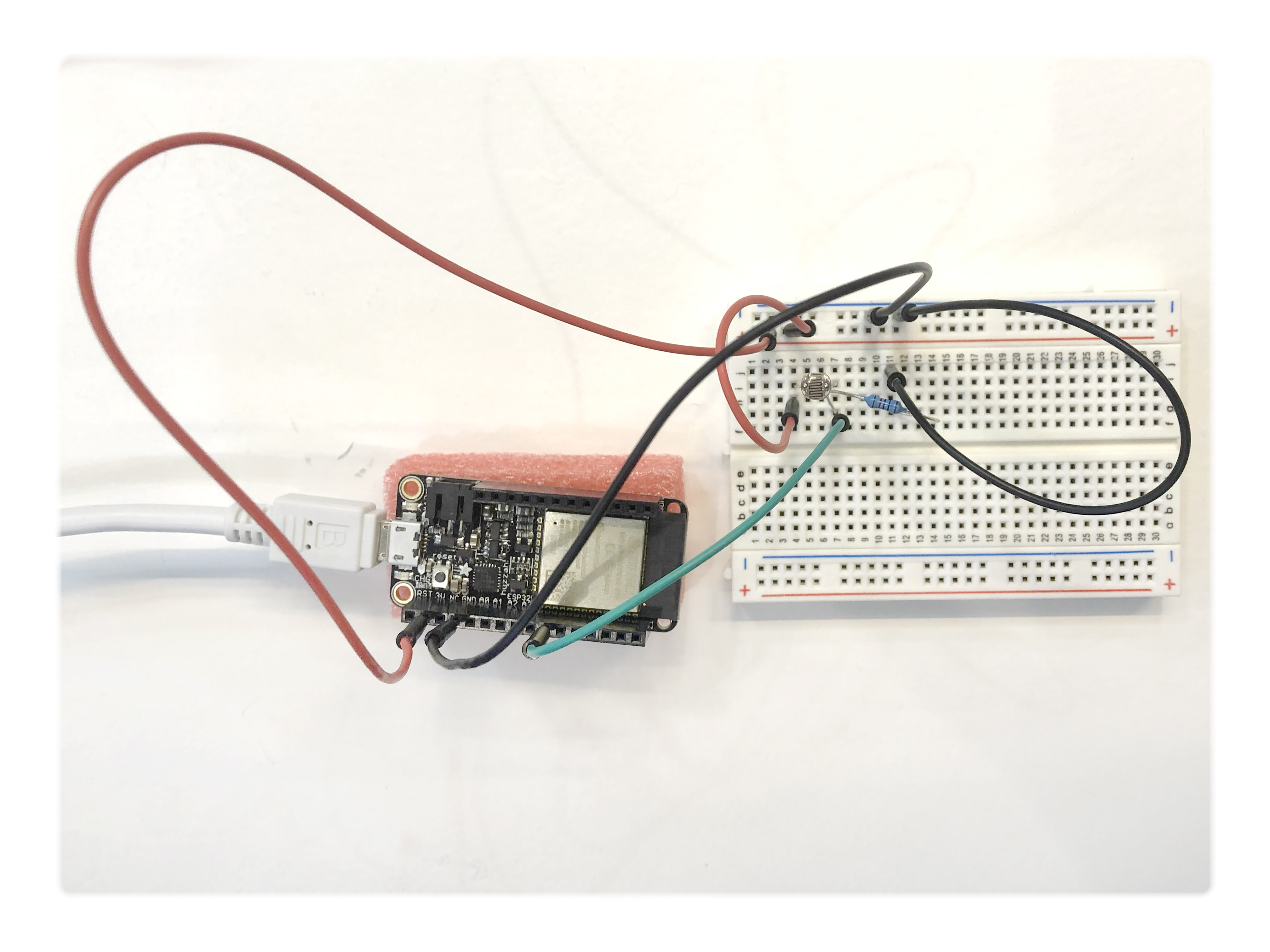
 for this exercise we used an light sensor as digital input
include <analogWrite.h>

int Sensor = A5;
int LED = 12 ;

void setup() {
  // put your setup code here, to run once:
  pinMode (Sensor, INPUT);
  pinMode (LED , OUTPUT) ;
  Serial.begin (9600) ;

}

void loop() {

  int SensorReading = analogRead (Sensor) ;
  Serial.println (SensorReading);
  int mapValue = map (SensorReading, 1300, 4095, 255, 0);
  mapValue = constrain (mapValue, 0, 255);
  Serial.print ("Maped value;   ");
  Serial.println (mapValue);
  analogWrite(LED, mapValue) ;
  delay (100);
}
Towelamp:
there is thousands of subtle but highly personal differences how we wear a classic shirt.
I was interested in finding an intuitive way to use the soft and uncontrolled nature of fabrics to harvest a wide range of personalized data.
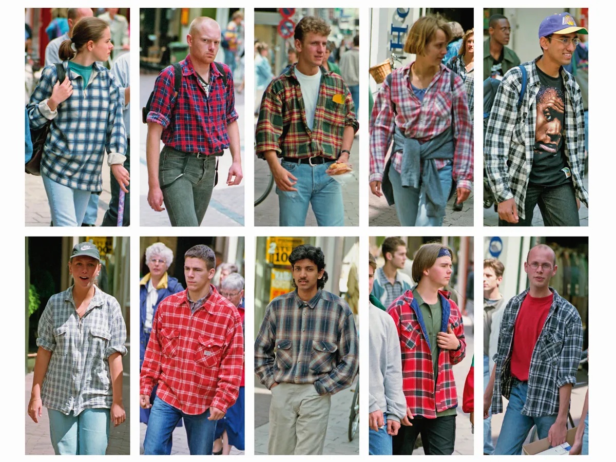 Hans Eikelboom
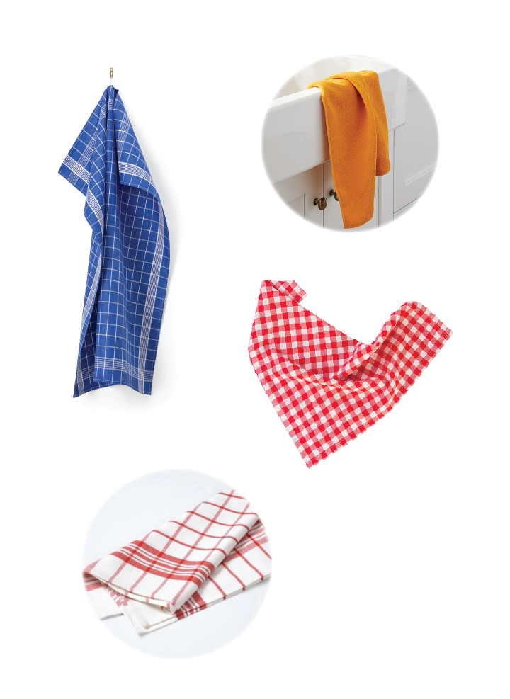
I decided to use an everyday kitchen towel as an example of a product that can be treated in many ways depending on the user’s mood and personality. Some people fold them carefully others threat them more rough.
 The ide was to turn it into a table lamp that dims not by a simple rotation dimmer but in a much more intuitive and personalized way.
I decided to place the analog sensor in a grid pattern mimicking a classic kitchen towel since it would give me a good spread of sensors.
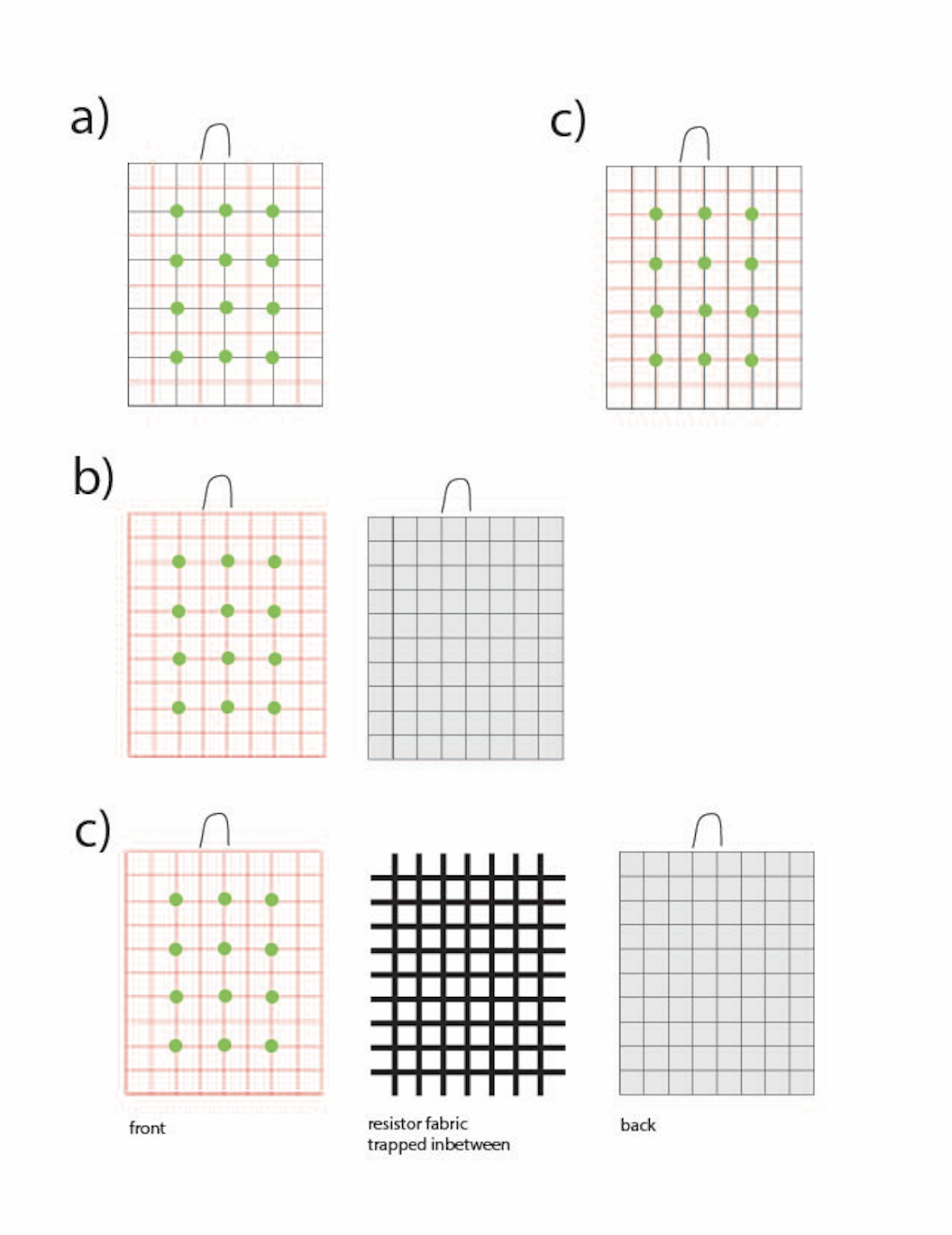
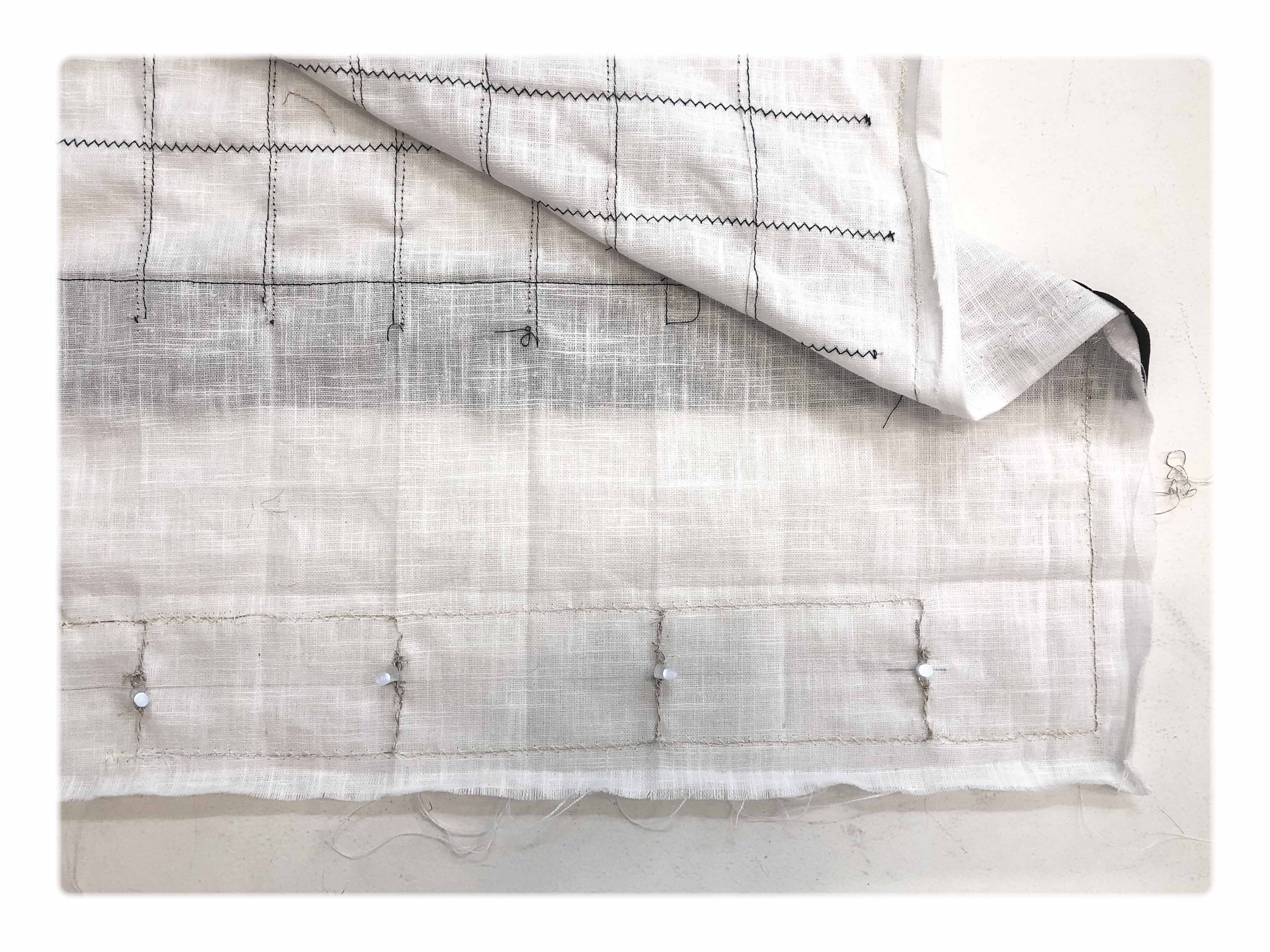
As swithch I made a simple pressbutton hook to hang the "towel"
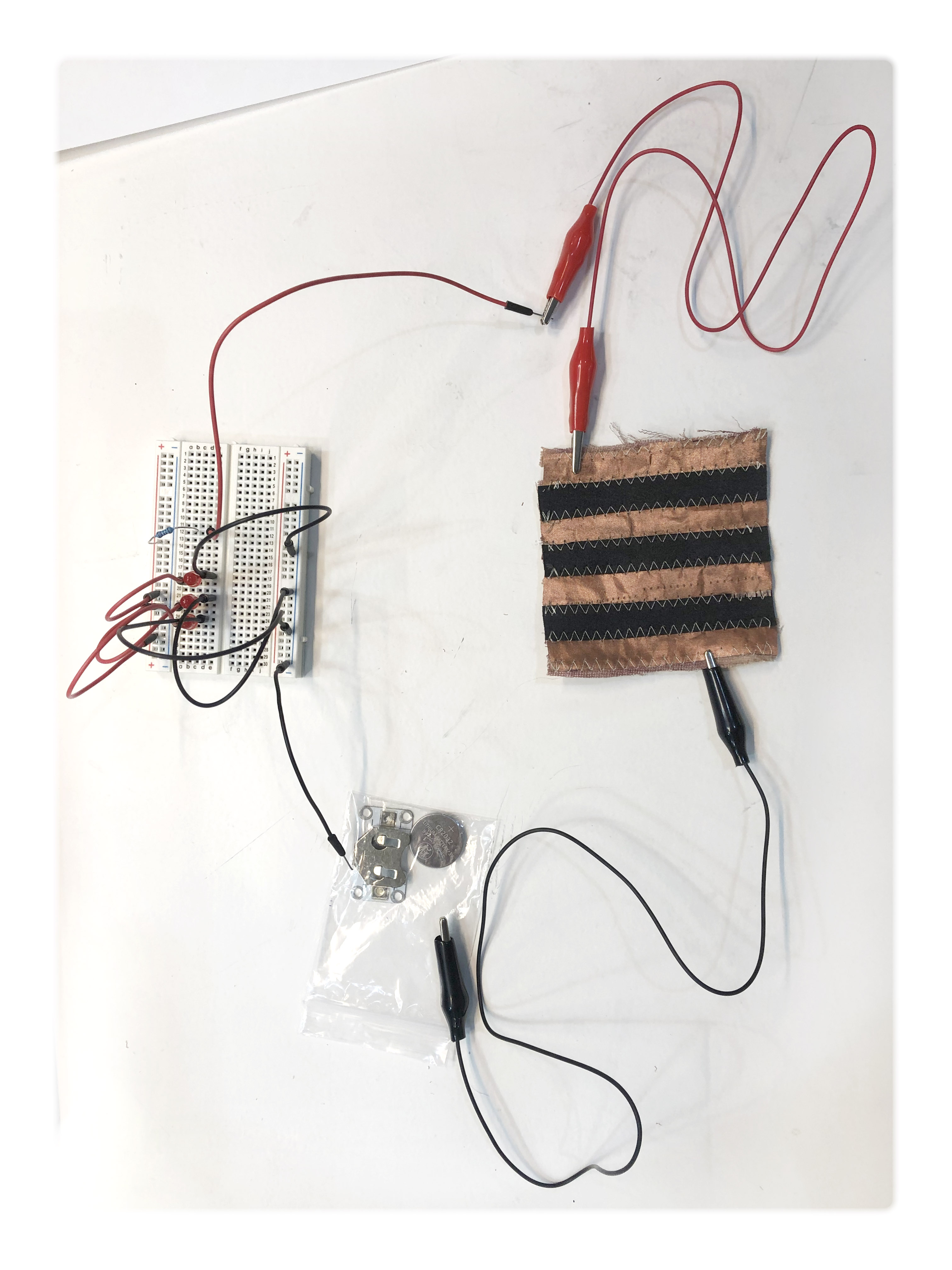
Sample A) (left) Strips of conductive copper fabric and resistant Eontex fabric stitched together
Sample B) (right) Strips of Eontex fabric and conductive thread(machine stitched)
 _A) resistance 10 ohms
 _B) resistance 16 ohms
In the end a decided to use sample B since the conductive thread gave a softer touch to the “towel”
To simplify the design and save fabric I decided to only use one (slightly thicker) strip of Eontex fabric since the residency effect would anyhow be the same.
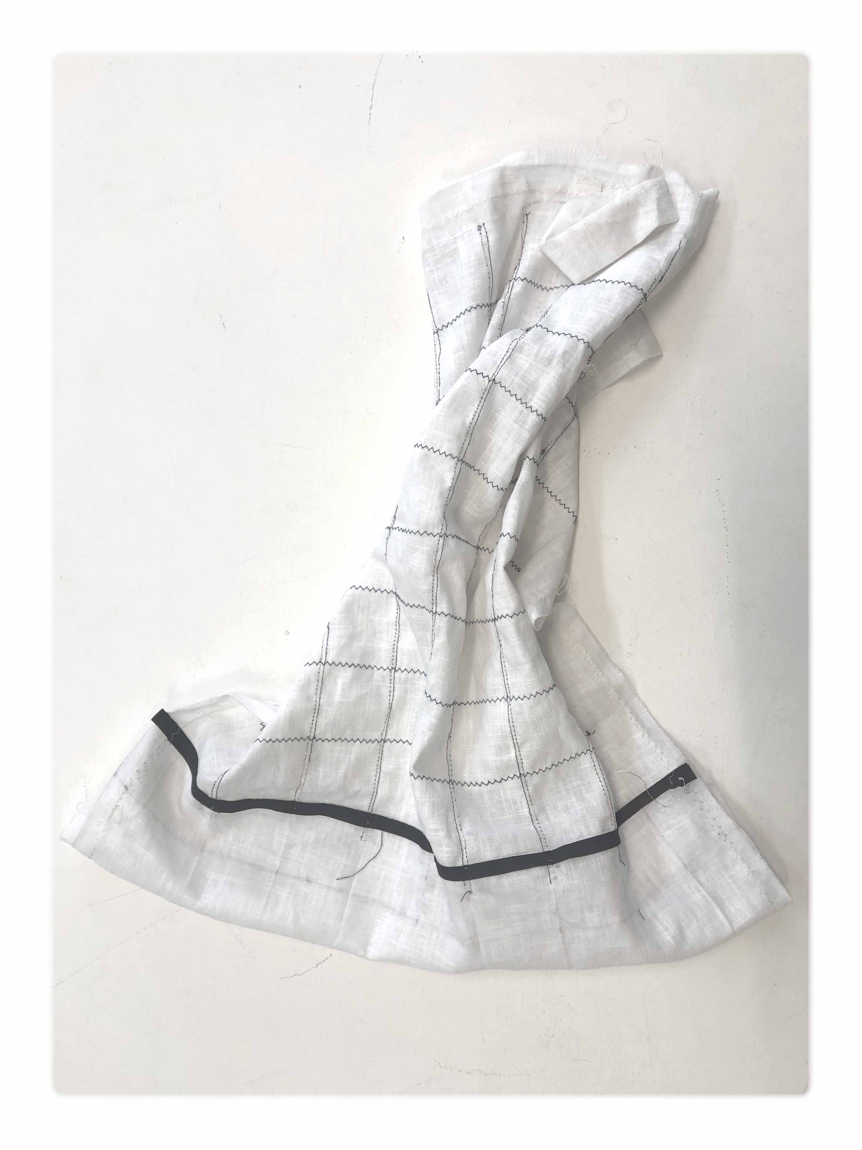
 final design
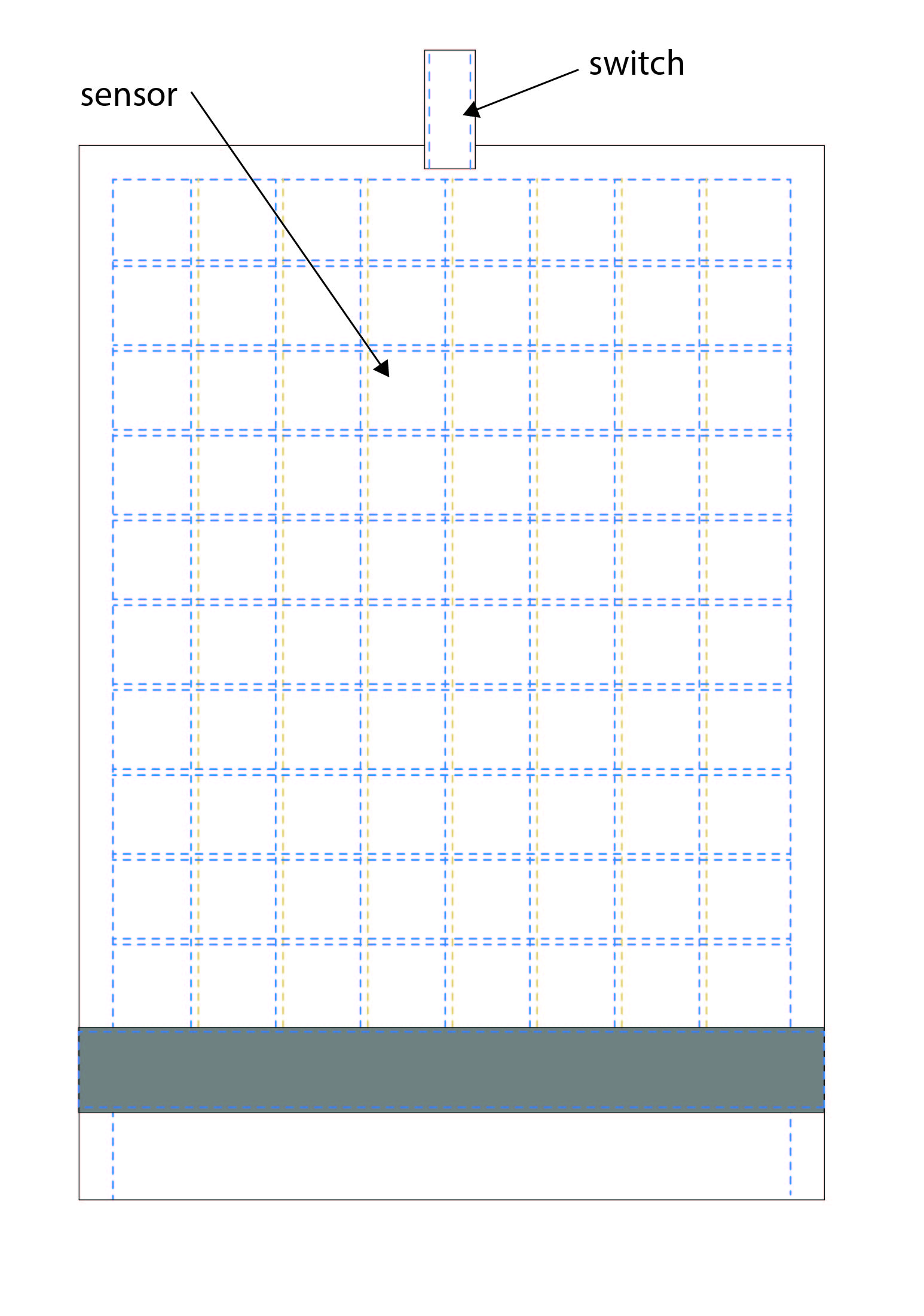
 simple snap button switch + sensor grid
vertical lines are stitched with conductive thread (front and back)
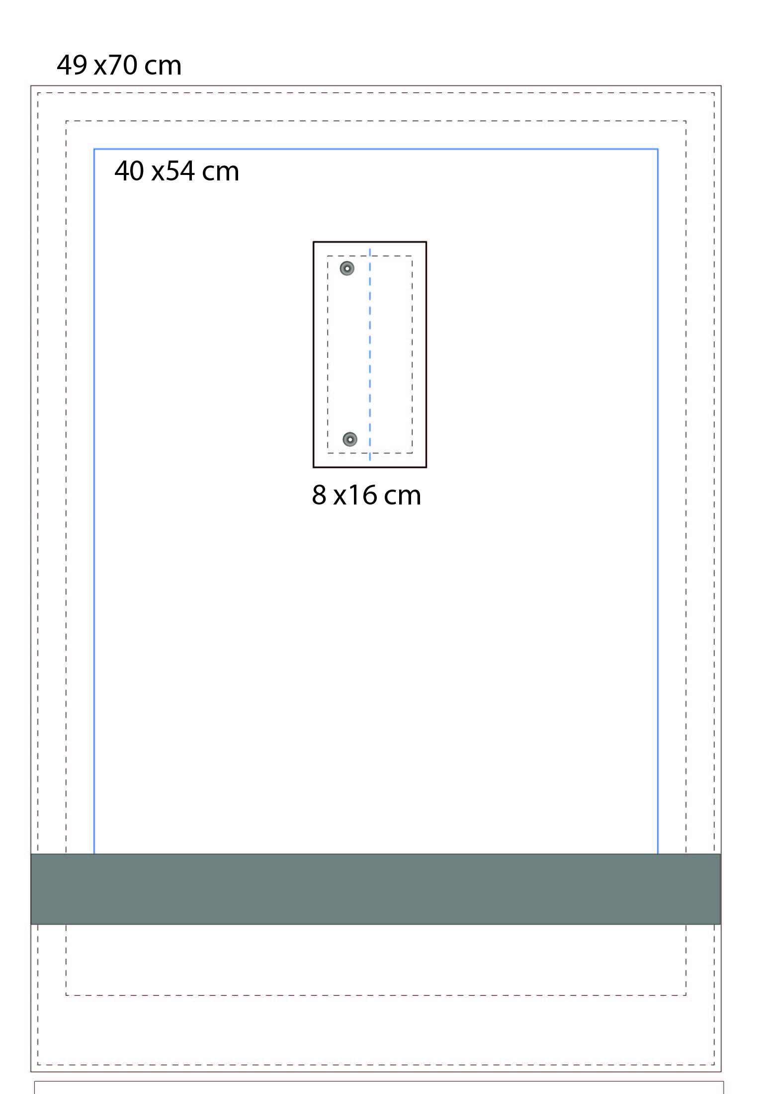
sewing pattern
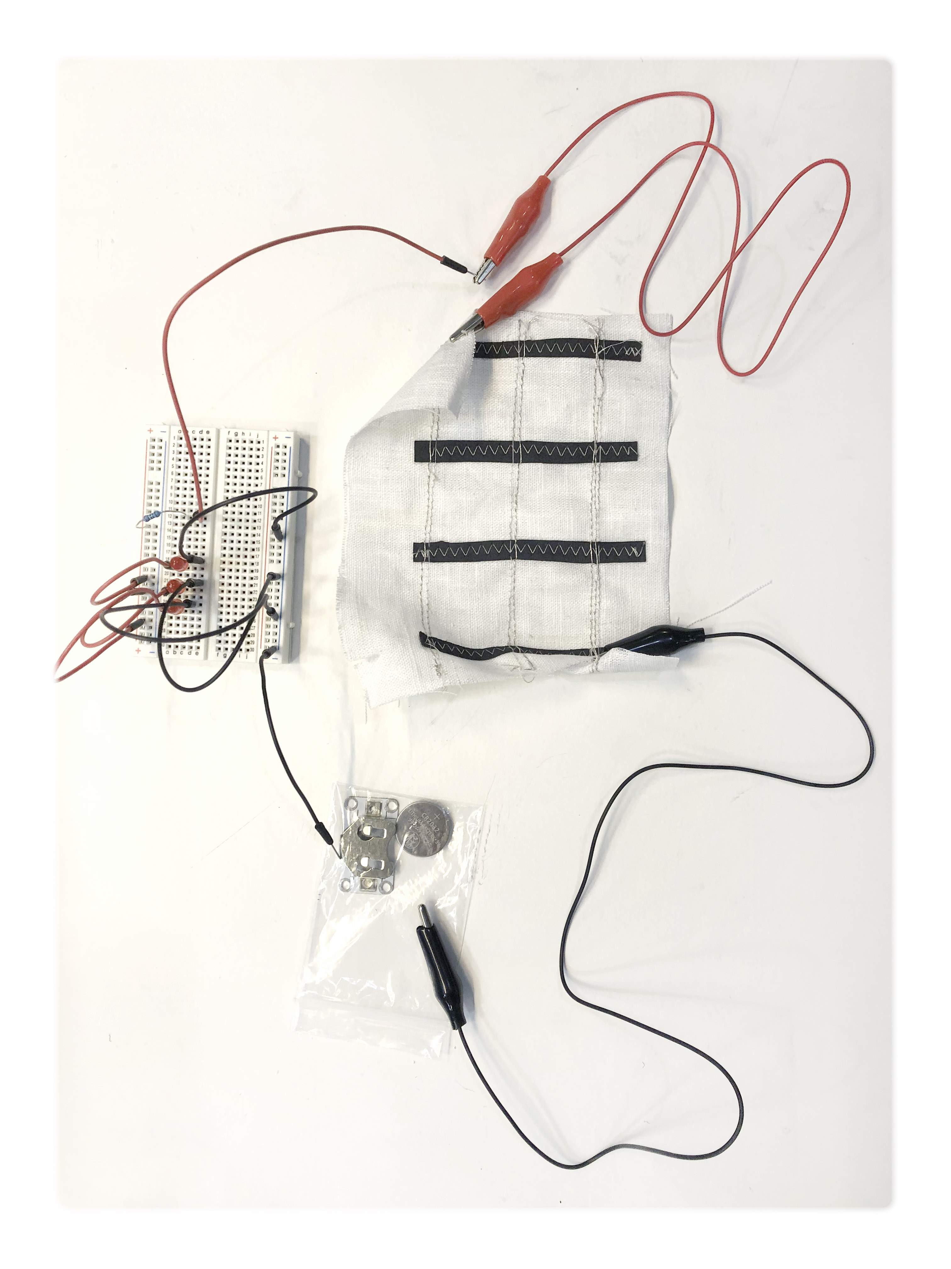
fabrication:
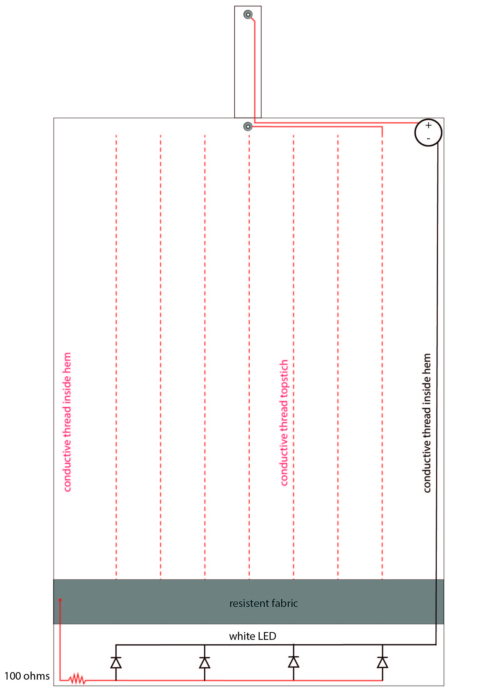
I used a single layer linnen fabric as base for the "towel".
LED was handstitched directly to the fabric and hidden in the hem of the towel.
I used Eontex fabric as the resistor, it was cut into a decorative strip and then topsticed to the base fabric.
The conductive thread was stiched horistontas as a double line (for the grid). The machine can only take the conductive thread as boobin thread, thats why I had to stich two lines front and back on the linnen fabric.
Horisontal zigzag lines are purely decorative
When I scaled up the design from the original small sample the resistance turned out to be to much to power my LEDs, even after cutting the Eontex fabric into a much smaller stripe then originally planned I had 618 ohms as resistency (original sample 16 ohms).
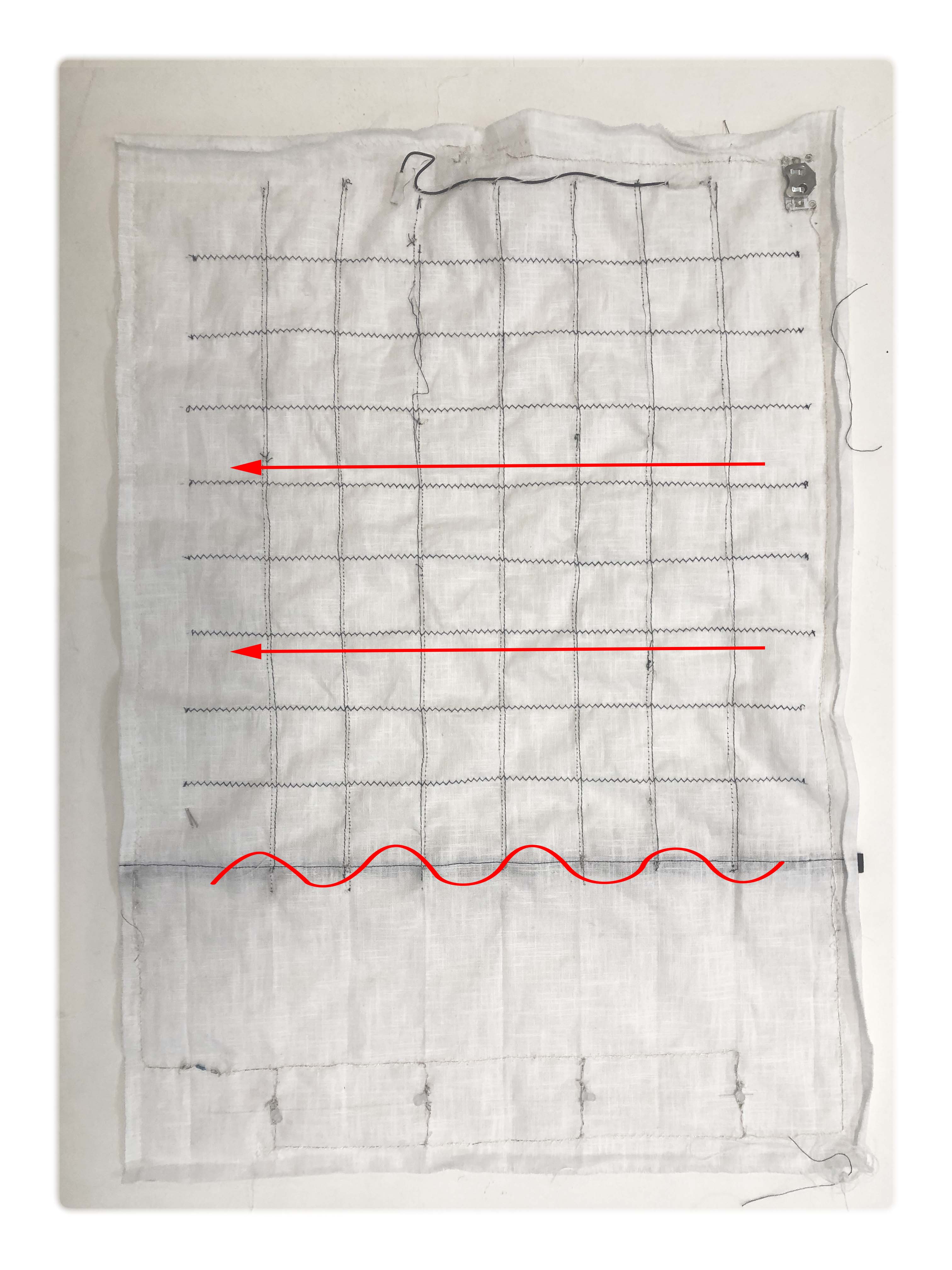 direction of the sensor from right to left
 current to weak to properly light up the LEDs
 LED parallel connected
I decided to skip the battery pack and use a transformer that can translate AC to DC current. For this you need to be carefull. We used the ohms calculator to give us an idea about the strengh of current needed and then we carefully adjusted the voltage on the transformer starting very low and slowly increase the current until the LEDS was bright enough.
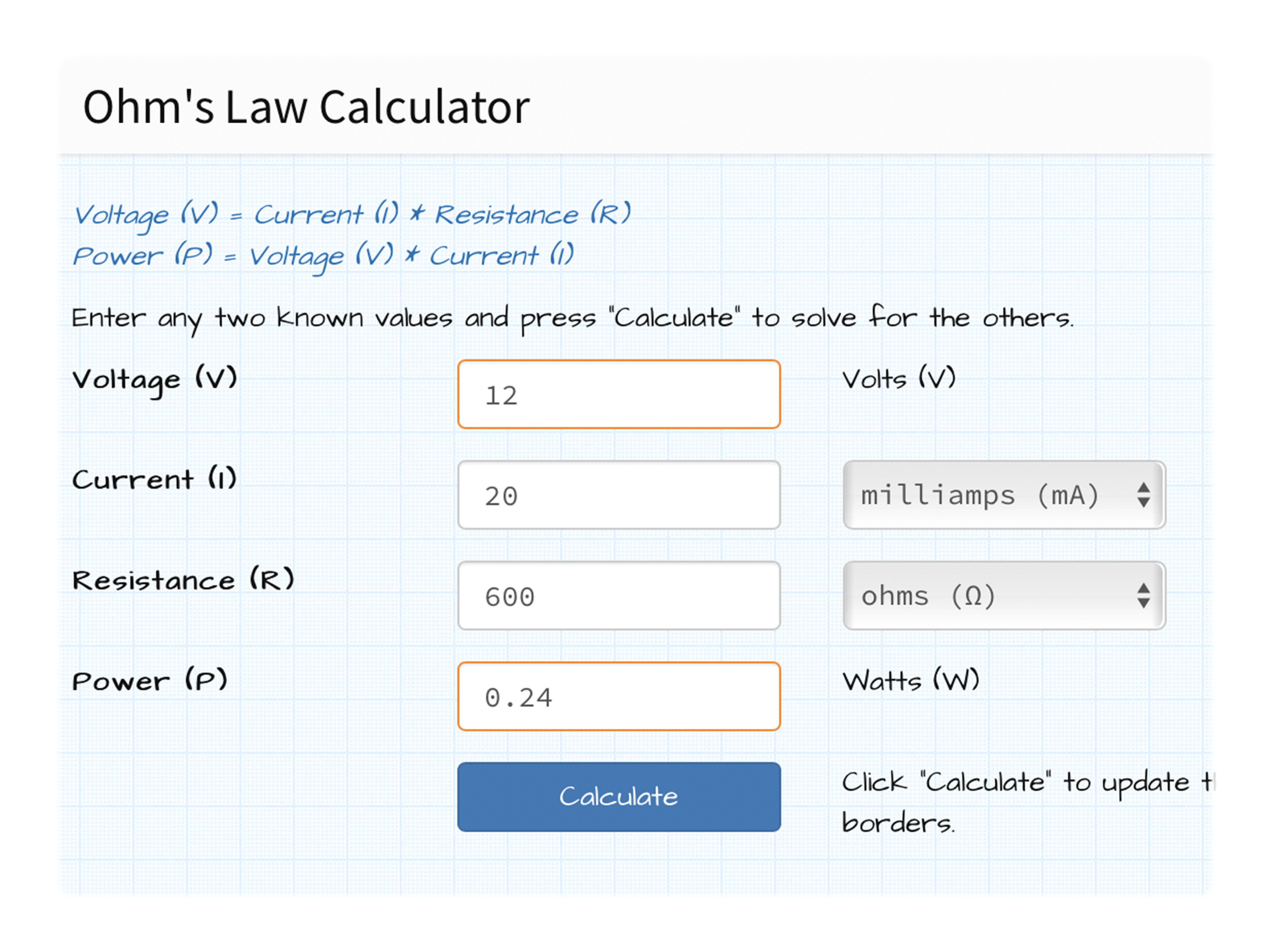 ohms law calculator
 Arduino (see analog write) to read the valus we got from the sensor:
include <analogWrite.h>

int Sensor = A5;
int LED = 12 ;

void setup() {
  // put your setup code here, to run once:
  pinMode (Sensor, INPUT);
  pinMode (LED , OUTPUT) ;
  Serial.begin (9600) ;

}

void loop() {

  int SensorReading = analogRead (Sensor) ;
  Serial.println (SensorReading);
  int mapValue = map (SensorReading, 1300, 4095, 255, 0);
  mapValue = constrain (mapValue, 0, 255);
  Serial.print ("Maped value;   ");
  Serial.println (mapValue);
  analogWrite(LED, mapValue) ;
  delay (100);
}
Design av Alve Lagercrantz
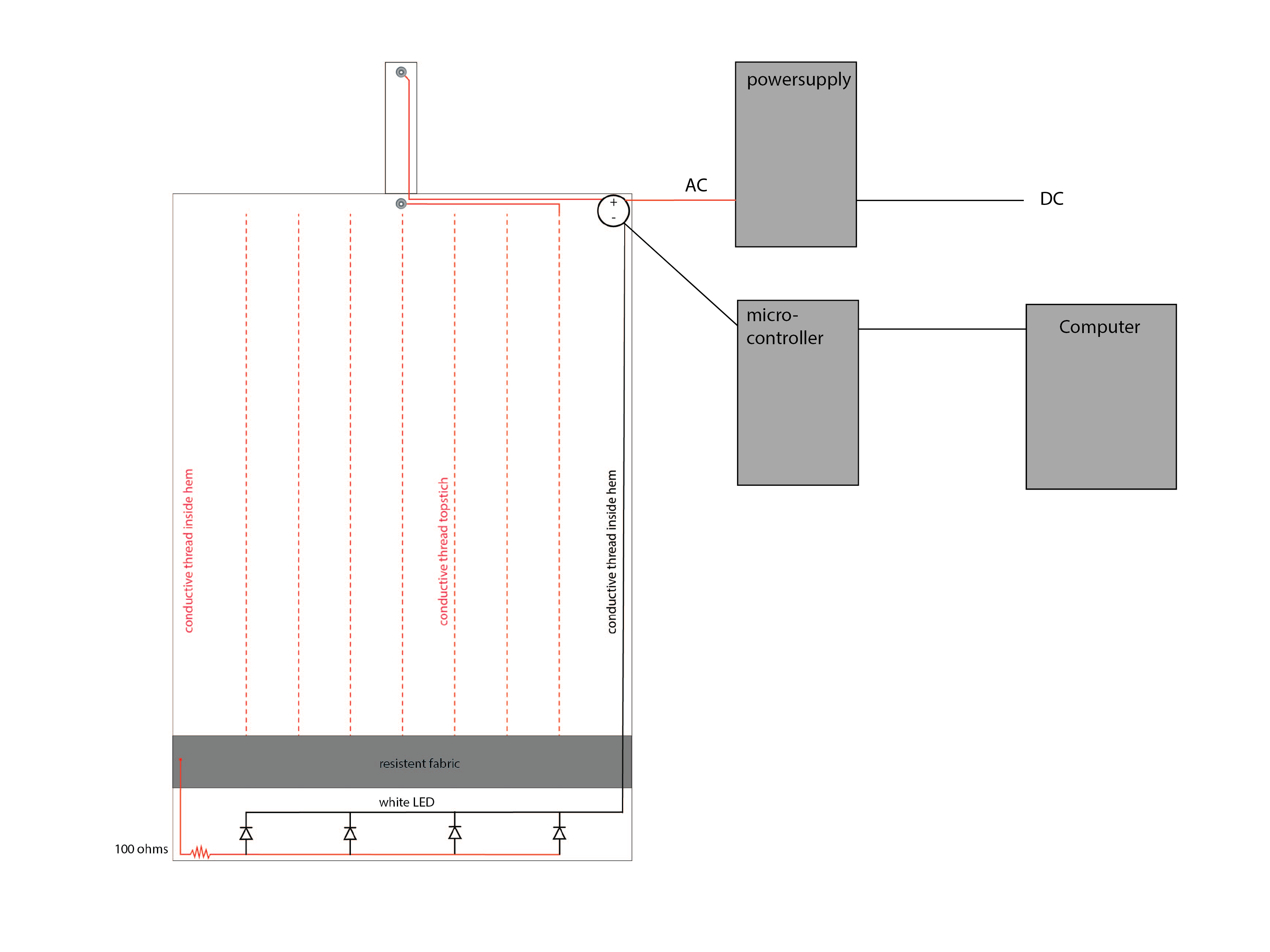 schematic
conclusion:
Even though my outcome was not as great as I would have hoped I still found the concept interesting, To continue the project it would be interesting to divide the input data in more specific terms. Like x and y input etc.
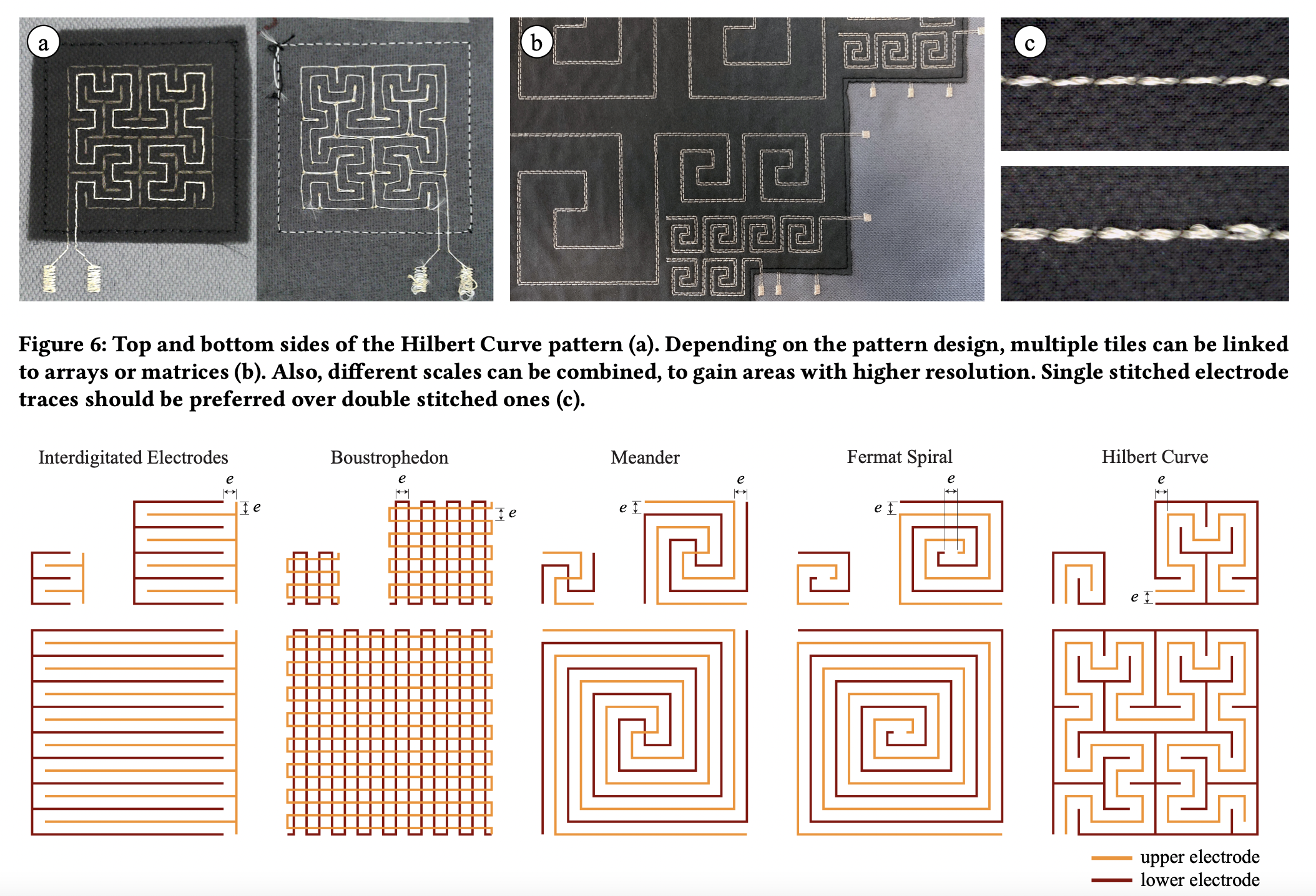
Other patterns could also be interesting to explore in order to get a more even spread of distribuition through all axies.
 mi-lab.org
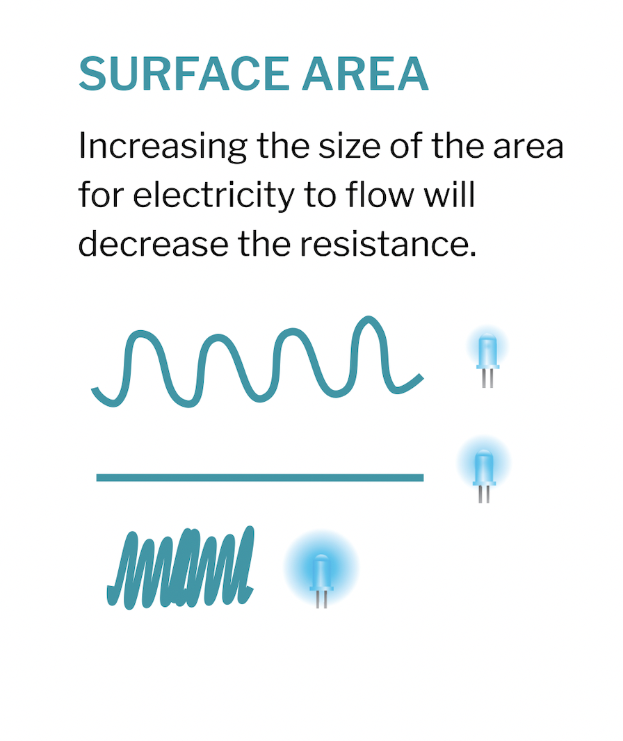
For the fabrication I think it would be better to use conductive tape instead of thread since it might give a better/stronger surface area.
mi-lab.org
For the fabrication I think it would be better to use conductive tape instead of thread since it might give a better/stronger surface area.
Or possible embroidered fields
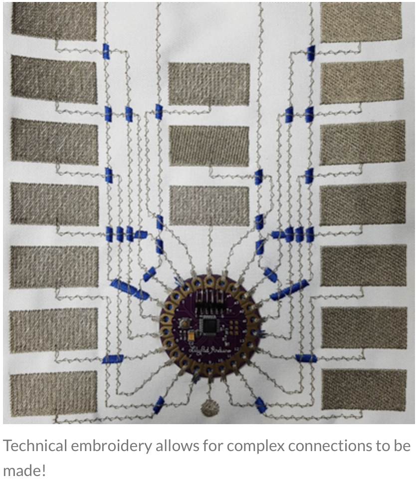
_smarttextiles
Some other (more clever) solutions for the concept:
touchbased fabric sensor
woven pressure sensor
woven pressure sensor
wireless textile