10. Open Source Hardware
INDEX IMAGE ~ Horizontal Loom, Tomb of Chnem-hotep
Research & Lecture
This week we are building our own open source machines with the goal to bridge the gap between artist/designer and the mechanic/technician/engineer.
To say that mechanics are not artists is to misunderstand thenature of art. They have patience, care and attentiveness to what they’re doing, but more than this—there’s a kind of inner peace of mind that isn’t contrived but results from a kind of harmony with the work in which there’s no leader and no follower. The material and the craftsman’s thoughts change together in a progression of smooth, even changes until his mind is at rest at the exact instant the material is right.
~ Robert Pirsig, Zen and the Art of Motorcycle Maintenance
In our assignment we will be:
- Understanding how a machine works
- Practicing test and impact analysis
- Developing, adapting and testing our machine (this becomes an ongoing process and relationship between designer and machine)
- Consolidate a service for future users (utilize material and tool lists, costs, data sheets, blueprints, recipes, assembly guides, source codes, schematics, videos and files)
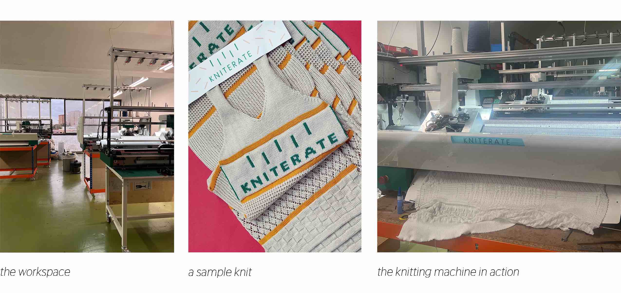
Trip to Kniterate
This week we were lucky to visit the Kniterate factory in Barcelona. They are a knitting machine company that makes this technology more accessible to small businesses and easier for designers to understand. The company began with Gerard Rubio's project to build his own open source knitting machine, and it grew from there. They write "We started Kniterate because we wanted to democratize clothing manufacturing. . . Until now this was only possible with industrial knitting machines, which cost upwards of $50,000, take a lot of space and require a technician to operate. We have re-imagined this industrial technology to deliver it to your space."
Open Source and Hacking Methodologies
Hacking
"is a do-it-yourself (DIY) practice of direct intervention, and its application manifests three main characteristics. Firstly, hacking is about the skill of opening a system, accessing it, and learning to master its circuitry, defenses, and structure. Secondly, hacking is a specific tactic of reclaiming and changing a system by plugging into it and redirecting its flows into a more desirable goal, usually by actively building on it, constructing a new improved system. Finally, the methods, techniques, and tools of the hack are shared freely among participants so that any-body can change or develop the new application however they see fit. Open Source, transparency, and free access are words often encountered among hackers."
Engaged Design and the Practice of Fashion Hacking
This article also provides interesting thoughts on how open source systems and hacktivism can be applied to fashion:

Biohacking or DIY Biology
"a growing biotechnological social movement in which individuals, communities, and small organizations study biology and life science using the same methods as traditional research institutions"
DIY Bio Org
Resources
DIY Flow Hood
Team Alve + Tomas + Anna is creating a Laminar Flow Hood for the Iaac Fab Lab bio lab. This will be helpful for plating bacteria for biochromes, plating and working with mycelium and any other experiments with sterile needs.
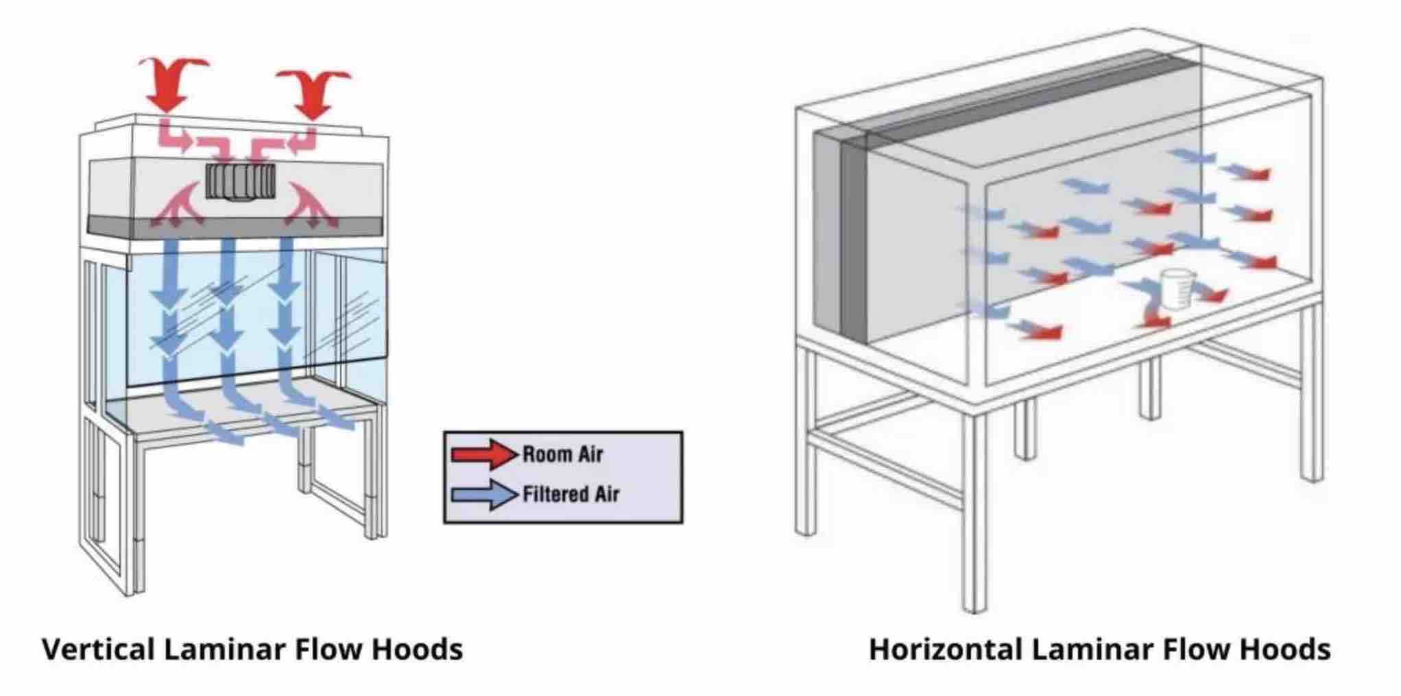
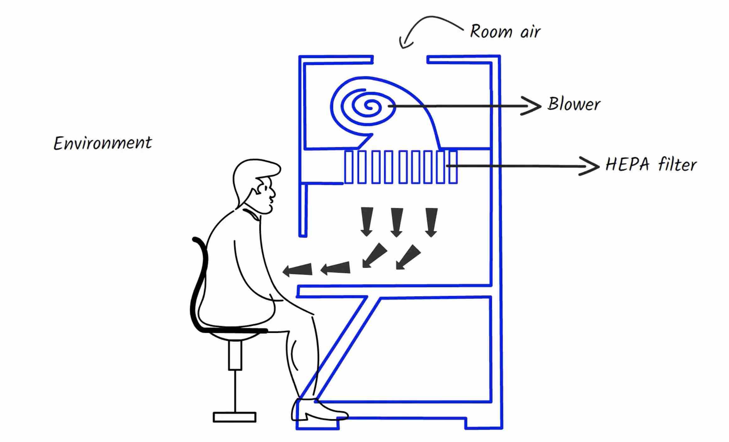
What is a Laminar Flow Hood?
A Laminar flow hood/cabinet is an enclosed workstation that is used to create a contamination-free work environment through filters to capture all the particles entering the cabinet. They are mostly used for aseptic distribution of specific media and plate pouring.
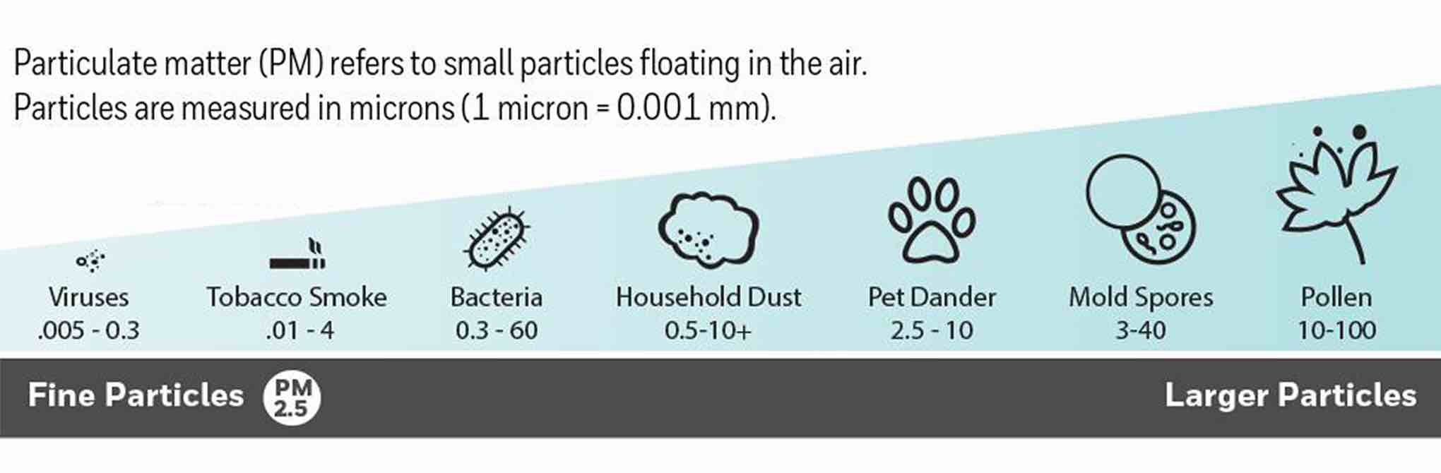
Prevent particles like these from contaminating your plates and organisms:
COMPONENTS
H14 Hepa Filter
HEPA is a type of pleated mechanical air filter. It is an acronym for "high efficiency particulate air” defined by the U.S. Dept. of Energy. This type of air filter can theoretically remove at least 99.97% of dust, pollen, mold, bacteria, and any airborne particles with a size of 0.3 microns.
Cabinet
The cabinet is best to be made of stainless steel with less or no gaps or joints for sterility. It provides insulation to the inner environment created inside the laminar flow and protects it from the outside environment.
The front of the cabinet has some glass shield which may open and close.
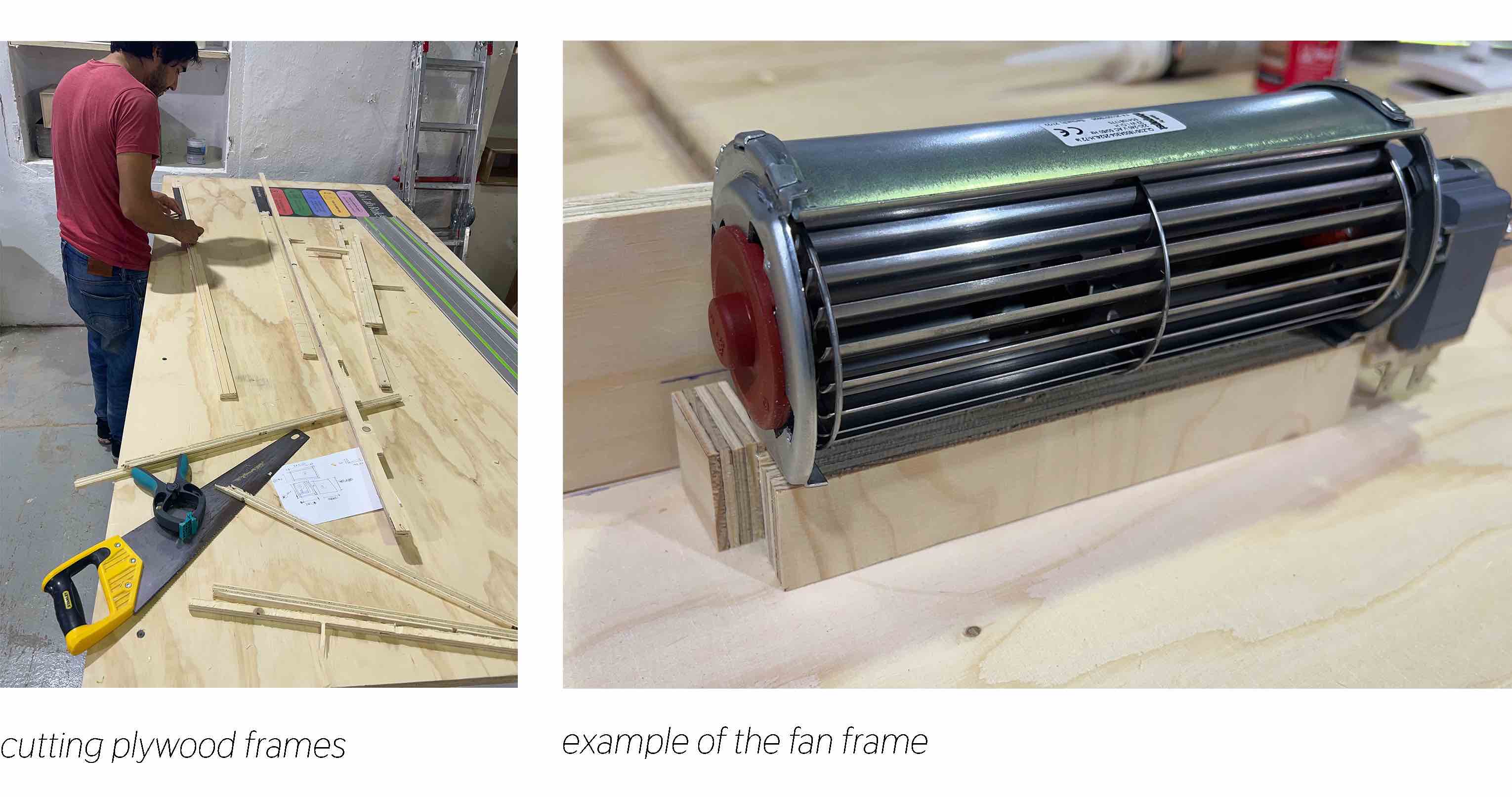
Fan/Blower
The fan sucks the air from the environment moves it towards the filter in the cabinet.
Pre Filter
optional This prevents any large particles in the environment from even reaching the fan.
UV lamp
optional UV light can be added in the cabinet to increase sterility.
Potentiometer
optional This is a dial that controls the level of the fan.
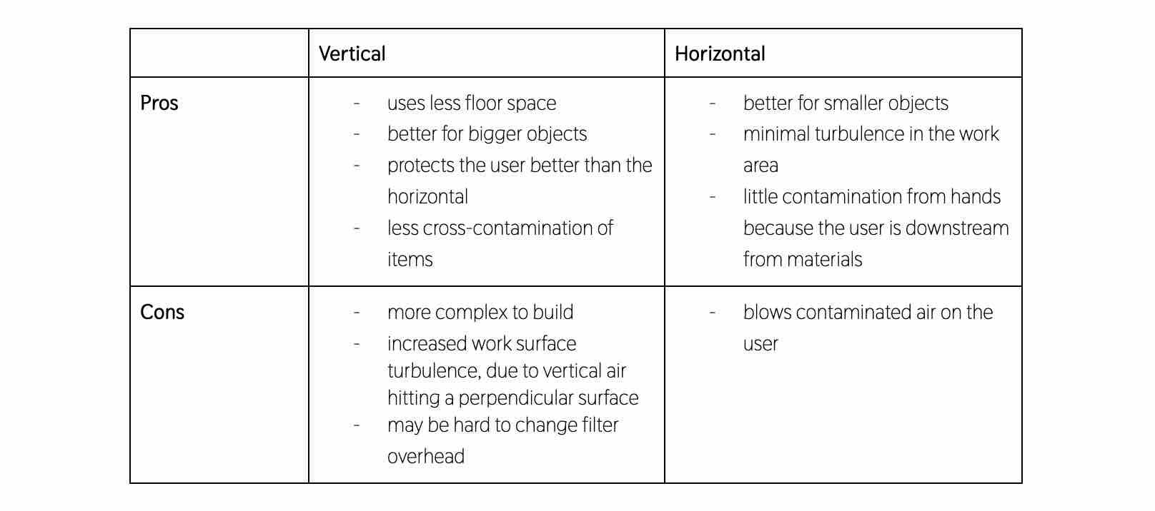
MACHINE VARIATIONS
Flow hoods can come in vertical or horizontal format and in different sizes.
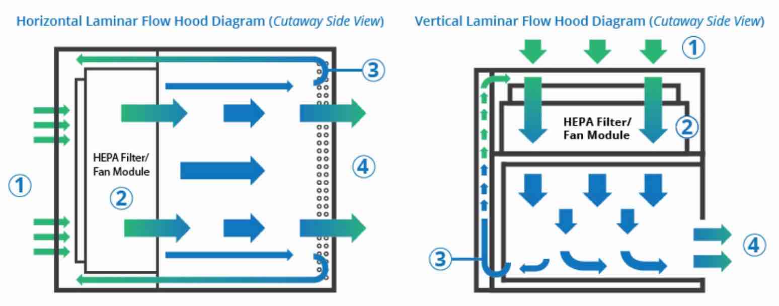
AIR FLOW VISULIZATION
Previous DIY Refrences
We are following a few past refrences, including Annah's project last year, taking suggestions and strategies from all to design a flowhood unique to our space and needs.
Materials
| Image | Description | Price | Link | Notes |
|---|---|---|---|---|
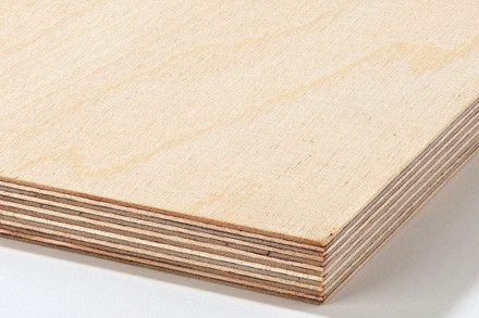 |
Plywood (x2) | ≈ 60 € | in IAAC | 15mm, 2400x1200mm boards |
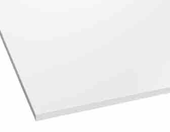 |
Acrylic Sheet (x3) | ≈ 38 € | in IAAC | 6mm, 500x1000mm boards |
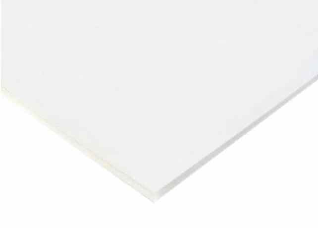 |
Kapa Foam (x4) | ≈ 7 € | in IAAC | 5mm, 1000x700mm boards |
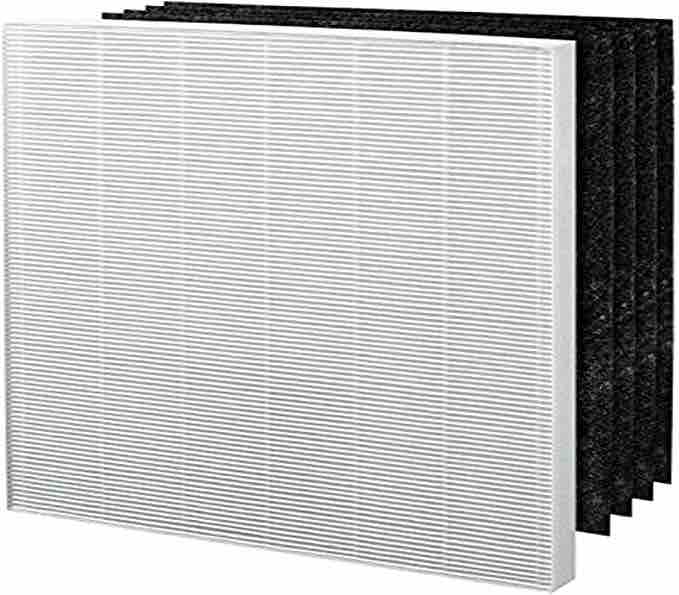 |
H13 HEPA Filter | 48,90 € | amazon | filters 0.1 microns and above, 33 x 28 x 3 cm |
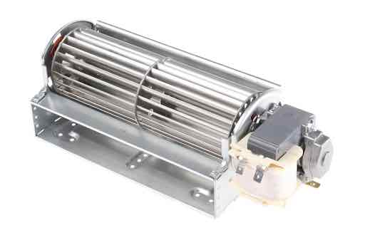 |
Fan | 67,34 € | RS | |
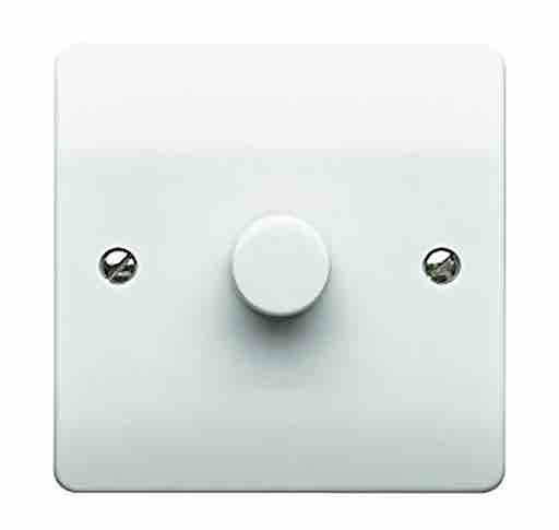 |
Potentiometer | 52,67 € | RS | To regulate the speed of the fan |
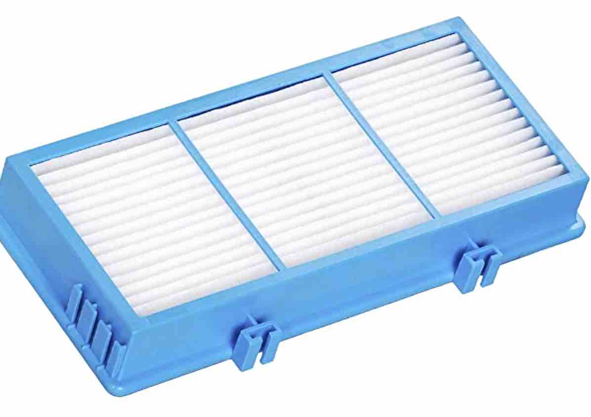 |
Prefilter | 20,19 € | amazon | filters particles larger than 2 microns, 25.4 x 12 x 3.5 cm |
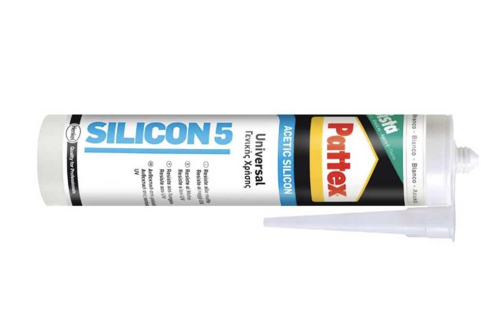 |
Silicone Caulk | 4.30 € | hardware store | to join and seal the acrylic pieces together |
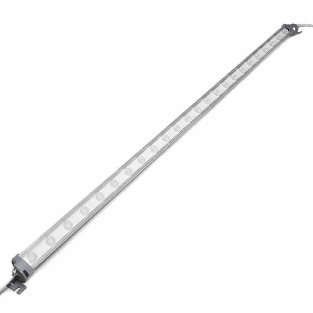 |
LED light | ≈ 10 € | in IAAC | |
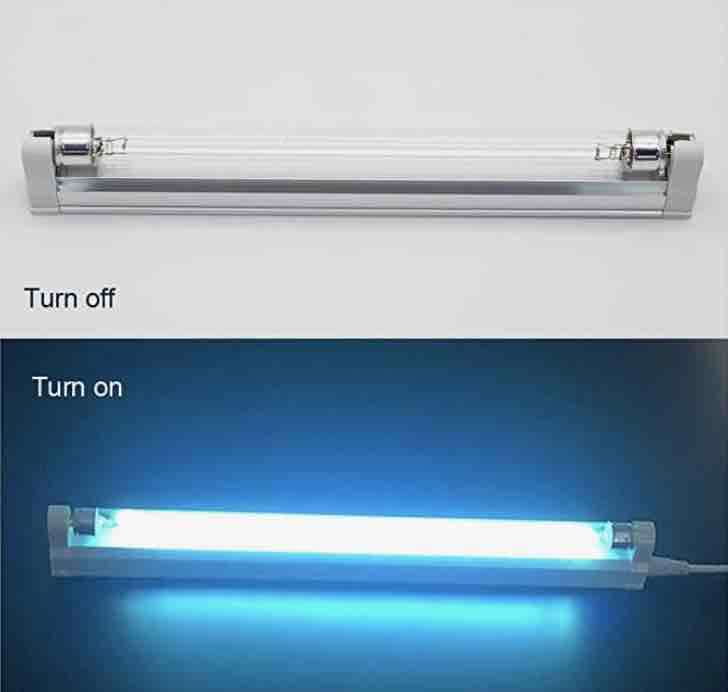 |
UVC light | 15 € | amazon | optional |
Other materials: screws and nuts, wiring, double sided tape,
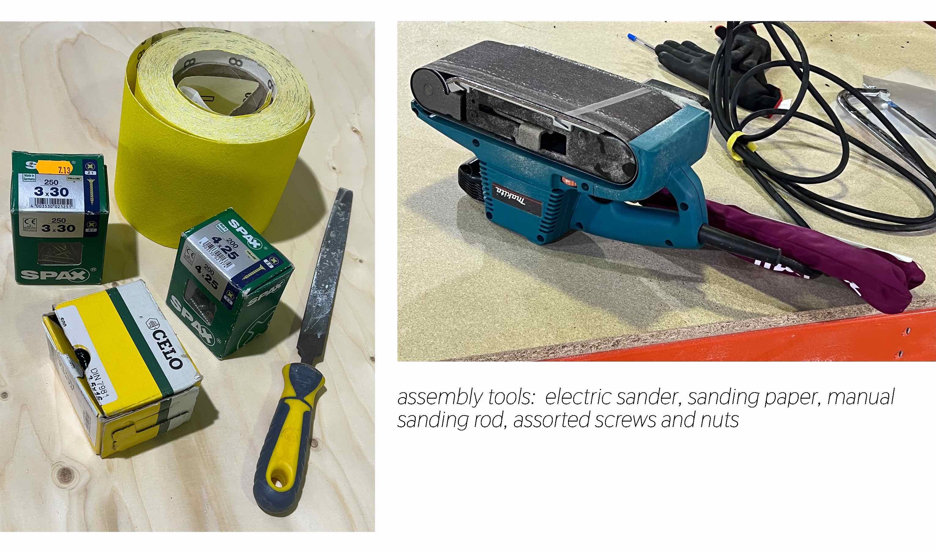
Tools
- CNC mill
- Laser cutter
- 3d printer
- Saw, hammer, drill
- Electric sander
- Manual Router
Process
Measurements and Sketches
Measurements of the section in the lab dedicated to the flow hood: 70cm depth x 85cm width.
Alve would like to be able to fit the 50cm tall 3d printer in the box for bio printing.
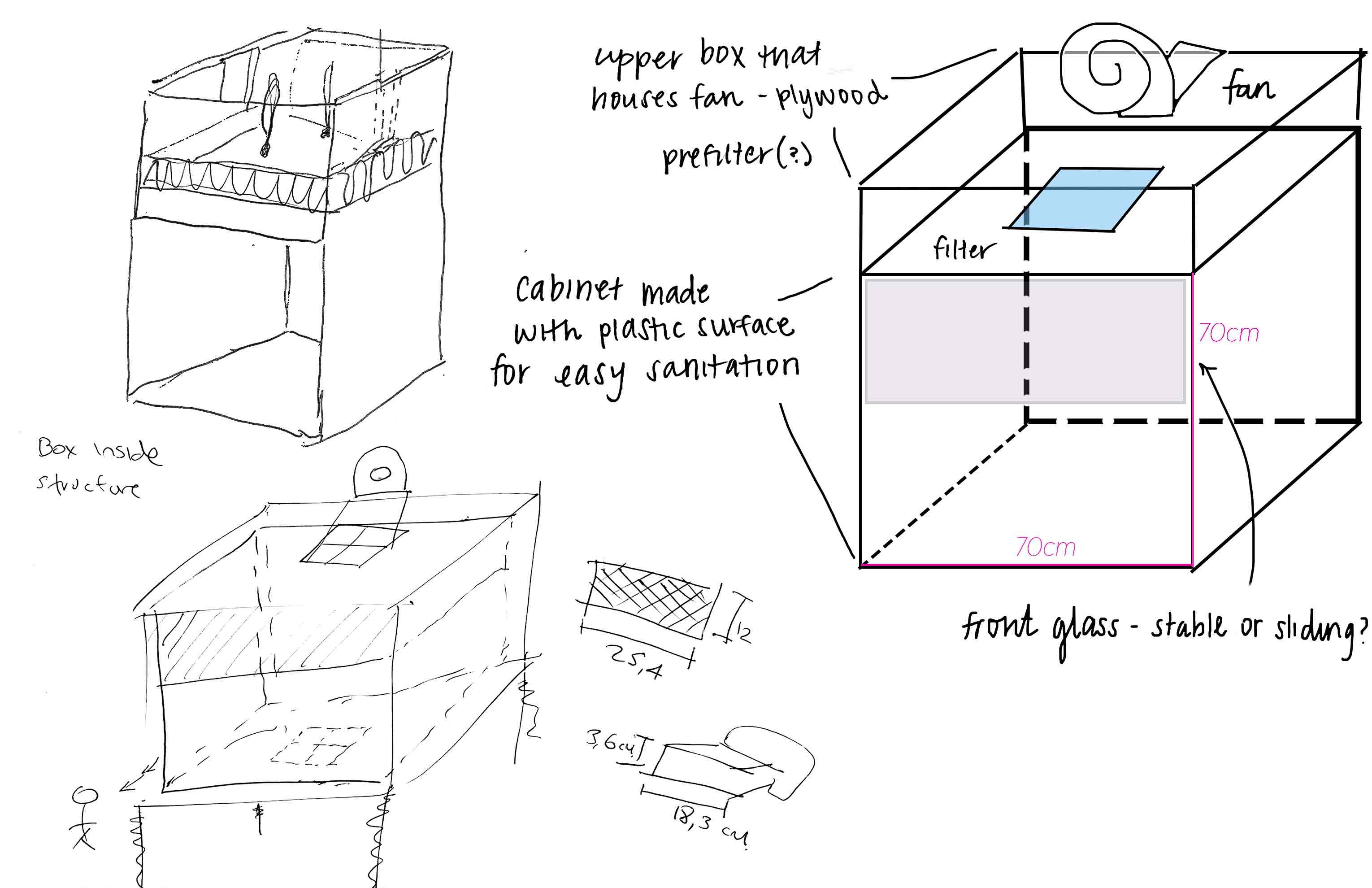
We decided to go forward with a vertical Flow Hood because we want to be able to work with larger items inside. It also works better with the smaller size filter that we can get. This is a general sketch of the vertical version (source):
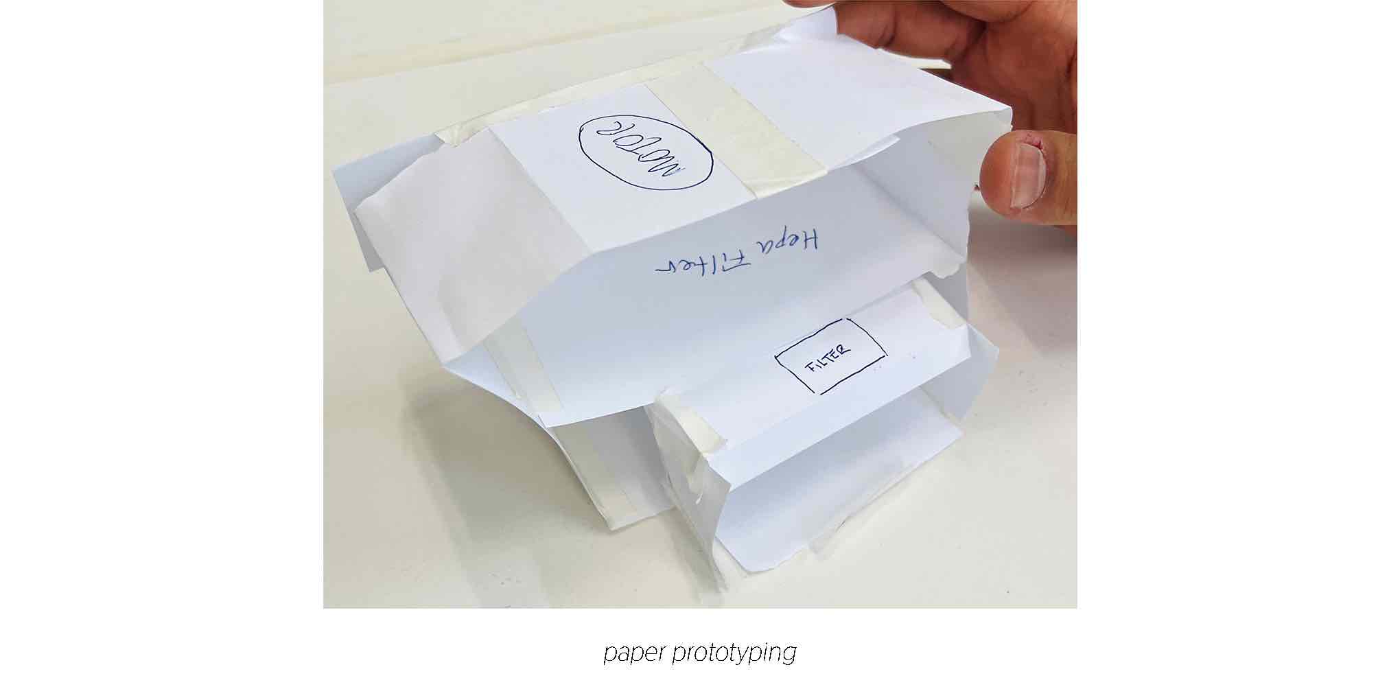
 We began sketching our design with a few things in mind:
- How can we design thinking about the future advancements we can make? (ex: adding a second motor later on, adding a UV light)
- Should we have an attached, removable or openable plexiglass screen? How should it open if so?
- How can we create seamless joints with the plywood?
- What sections need to be airtight?
- What sections need to be made with plastic in order to sterilize with alcohol?
Calculation
To obtain the Laminar air flow from our flow hood, we will use a squirrel cage type blower fan that is mounted on top of the hood. These fans are rated based on the volume of air that they produce at zero static pressure. As the static pressure increases, the amount of air the fan can produce decreases.
The volume of air that a particular fan can provide at a given static pressure can be shown in a “performance curve” which is usually provided by the manufacturer – See below curve (5).
With the aim to be in the working point of the blower, we defined that the stream of clean air should flow over the workbench at a speed of 20 meter per minute (red line from bellow’s curves). This means that the volume of air flow required can be determined by multiplying the area of the filter by 20 m/min.
In our case, a 0,33m x 0,28m filter will have an area of : 0,092 m^2. Therefore, the volumetric flow rate of clean air required for work is 0,092m^2 x 20 m/ min = 1,84 m^3/min or 110,4 m^3/hour.
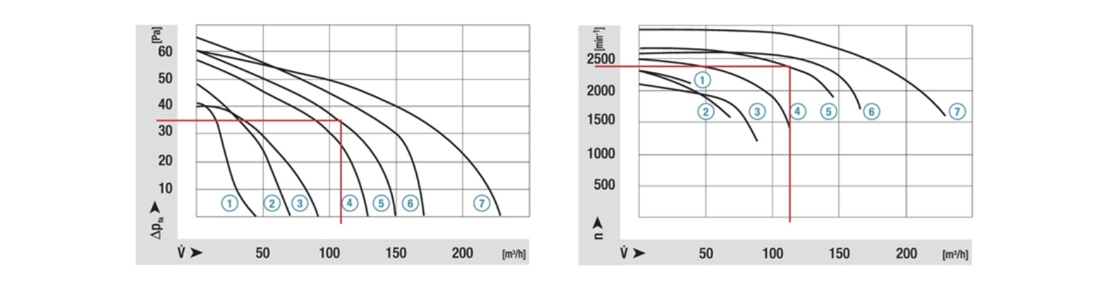
From the above calculation and the manufacturer datasheet of the blower, the volumetric flow rate of the fan at our static pressure by looking at the curve. As you can see, at 34 Pa of static pressure, this fan should provide a flow rate of 110,4 m^3/hour. This is called the working point, and since we require at least 110,4 m^3/hour, the fan should be adequate.
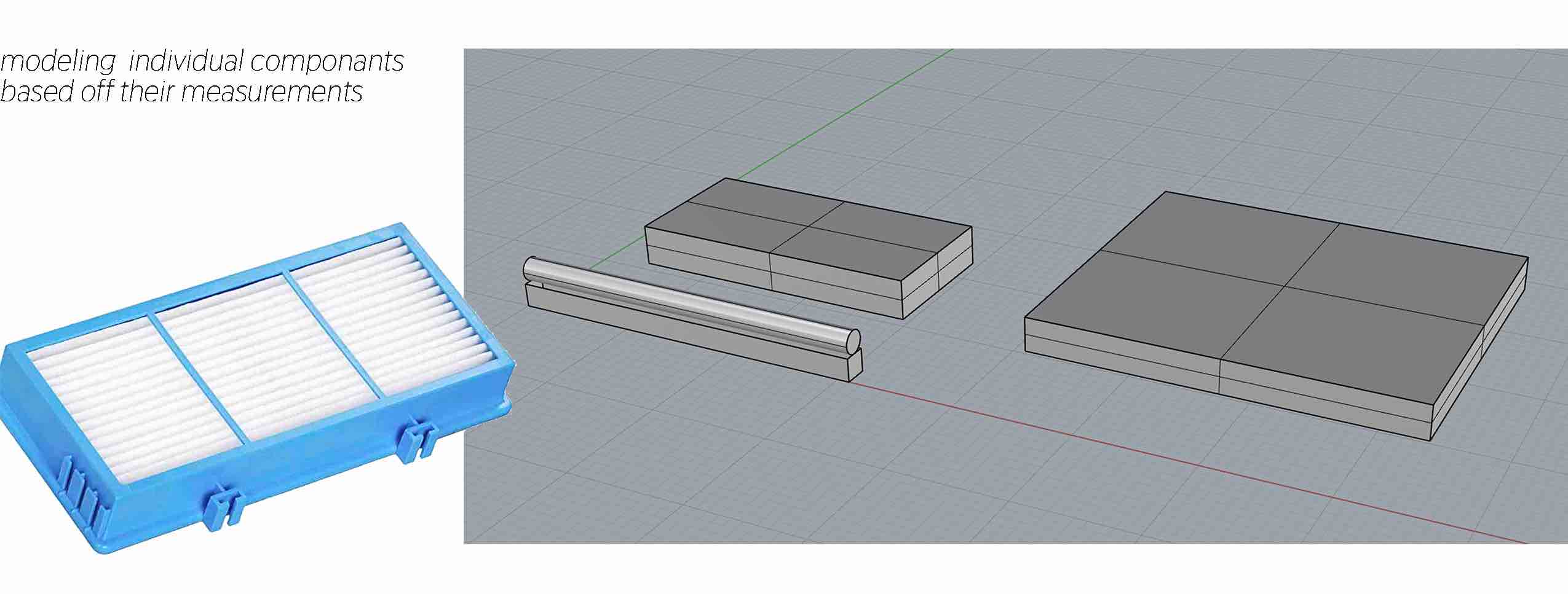
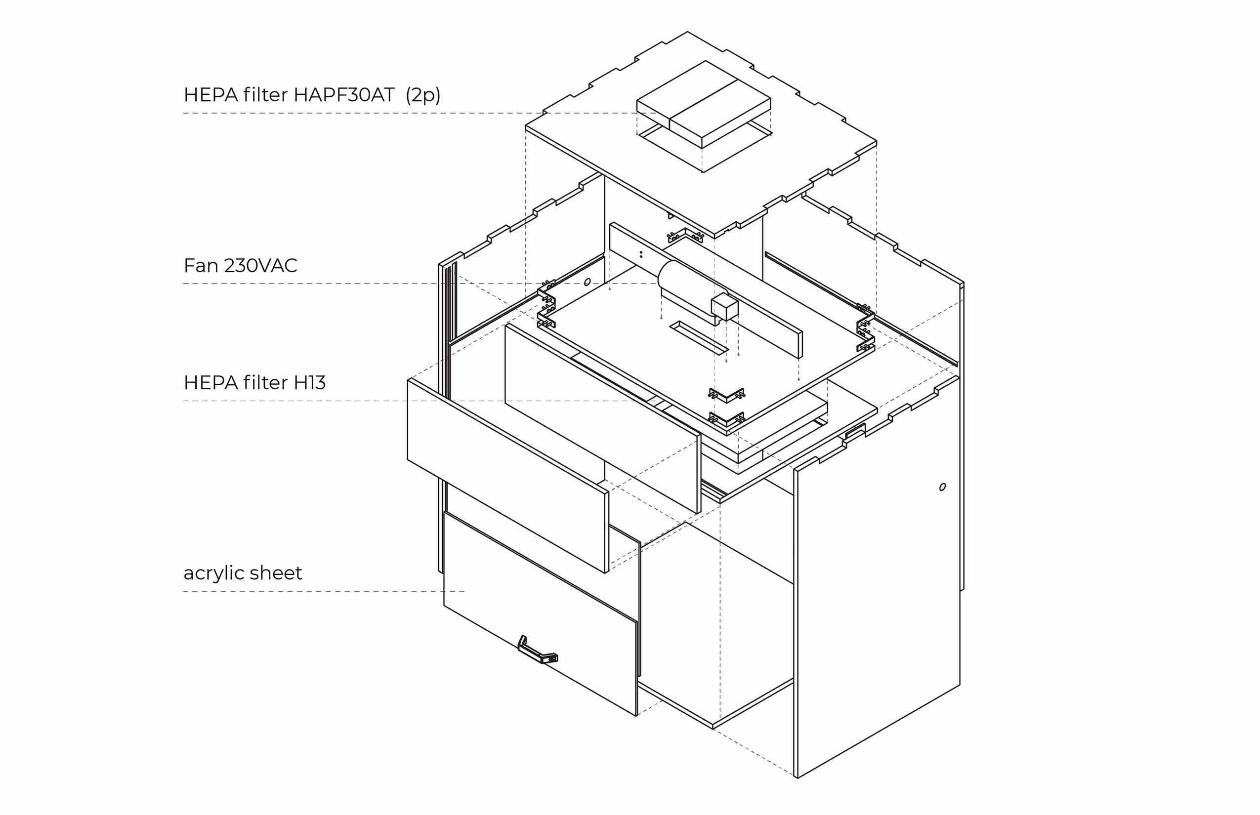
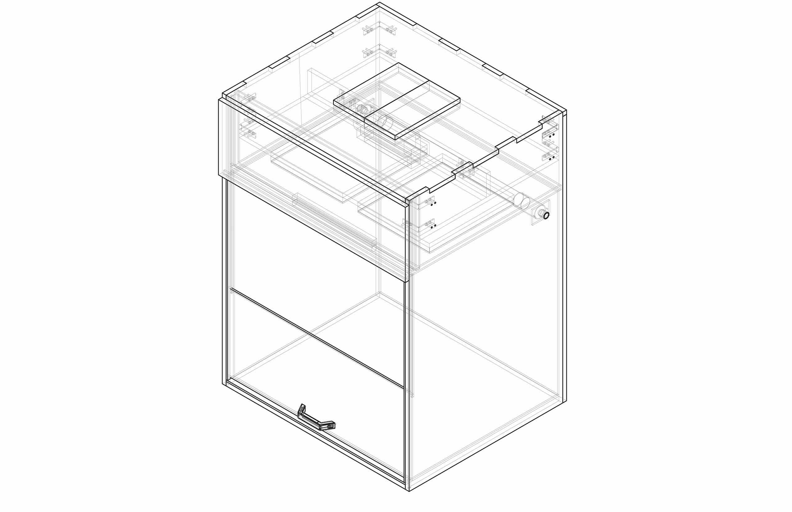
3d Modeling
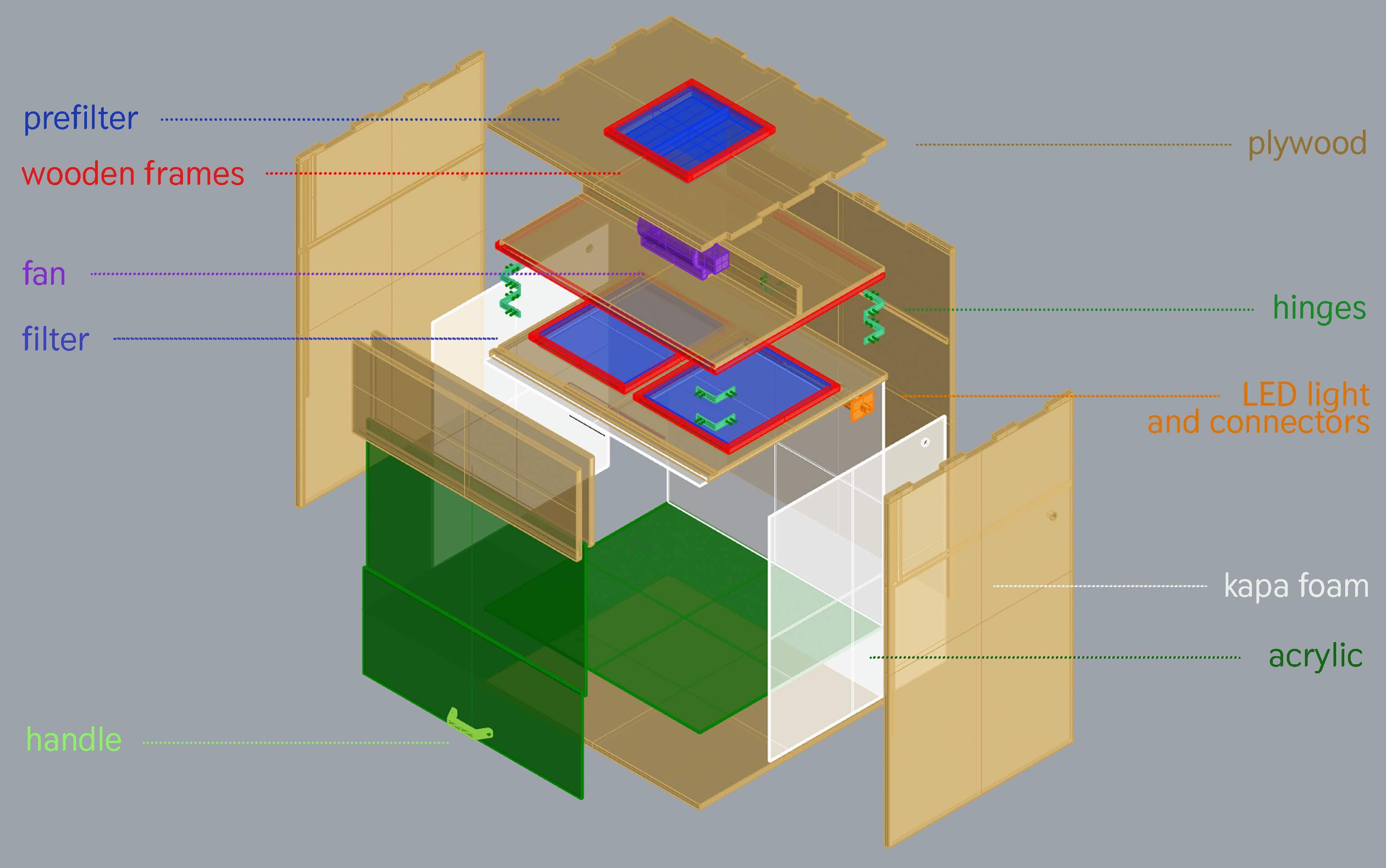
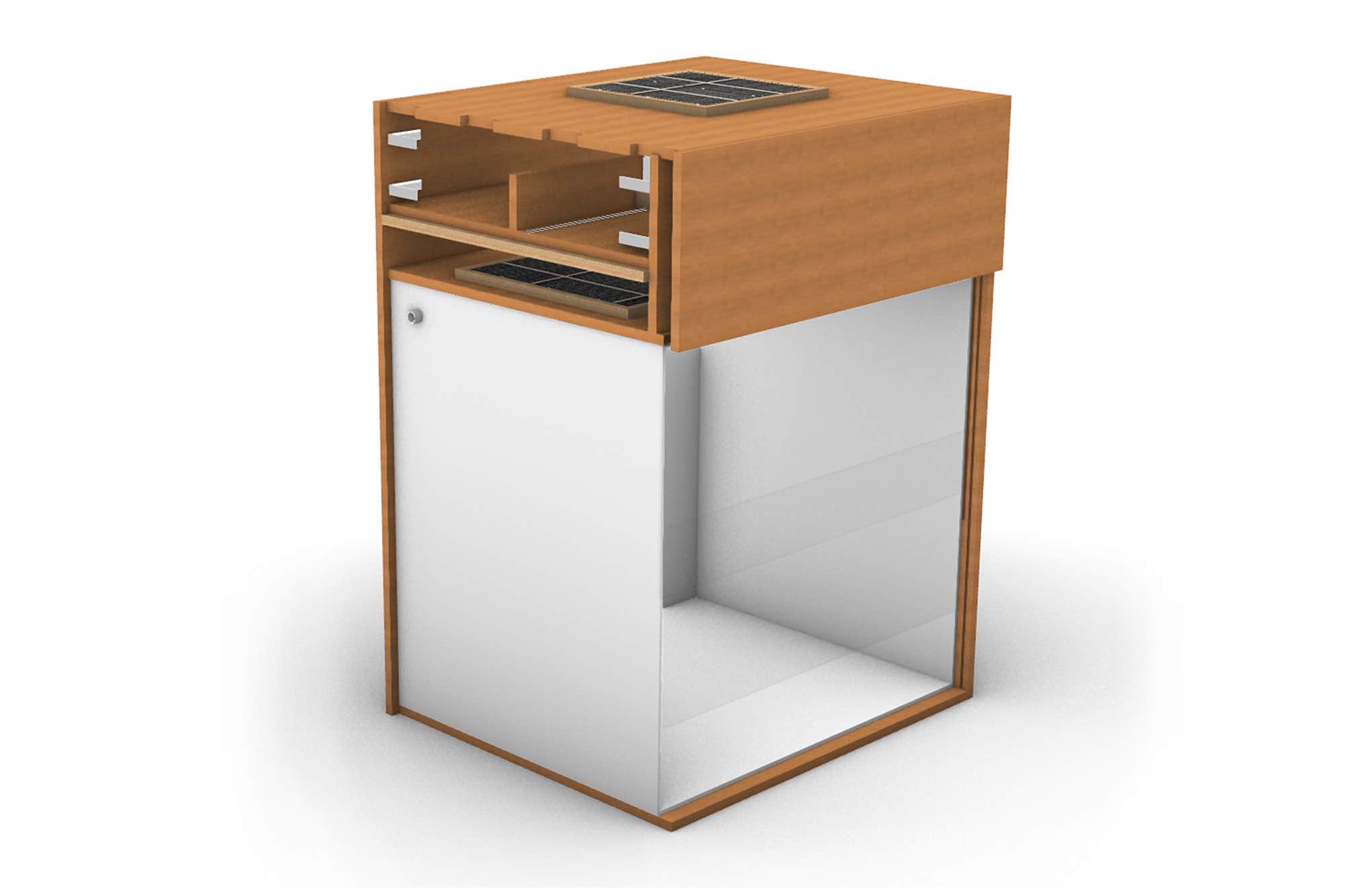
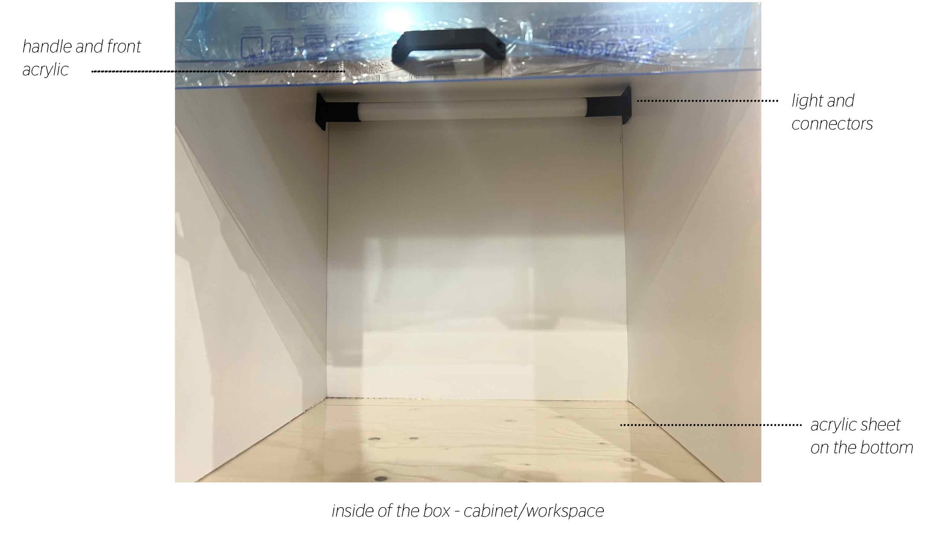
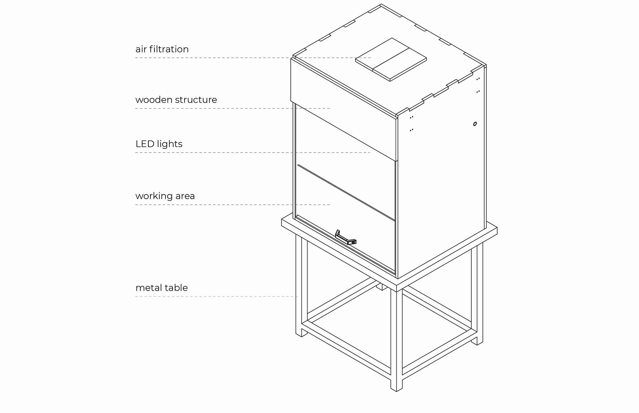
Alve started making our model 1 with a two part design: The outer structure box which will be cut from plywood and the inner workspace which will be cut from Kapa and acrylic. The fan will sit in the uppermost chamber and pass air through the filter below, which then flows into the workspace. We made basic 3d models of the componants based on their measurements to add to the design. Some elements we took into consideration:
- adding a wodden frame/base for the fan so it lays flush on the box
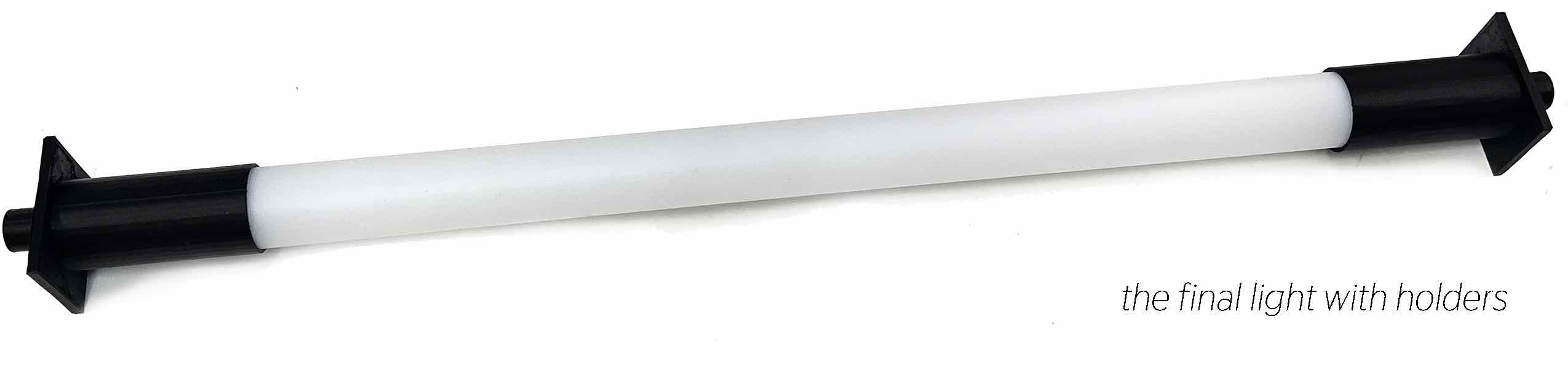
- adding an LED light in the back corder where it is darkest
- adding holes for wiring
- adding a section for an optional UV light
- designing a front acrylic sheet with 2 sliding parts that can be lifted up into the upper chamber for fitting larger objects inside the workspace
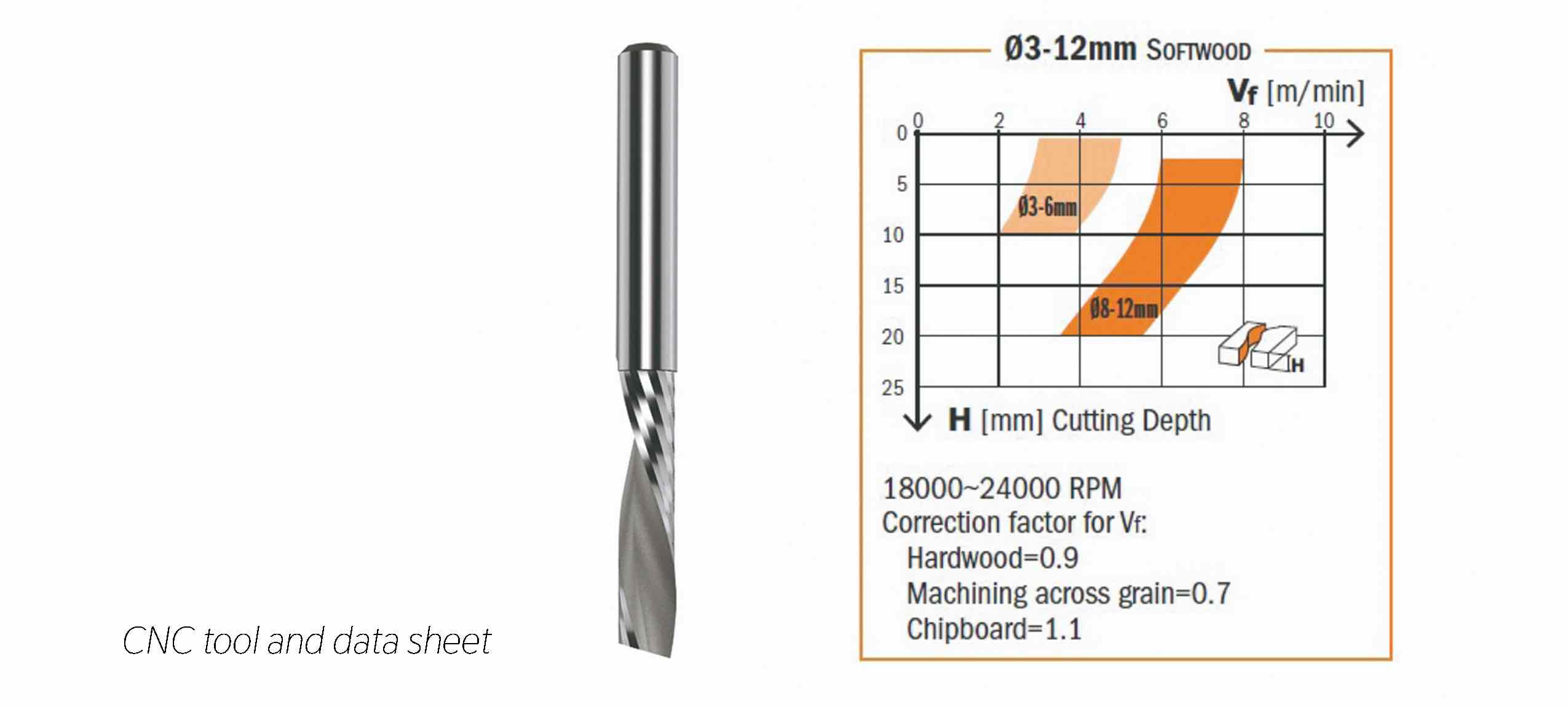
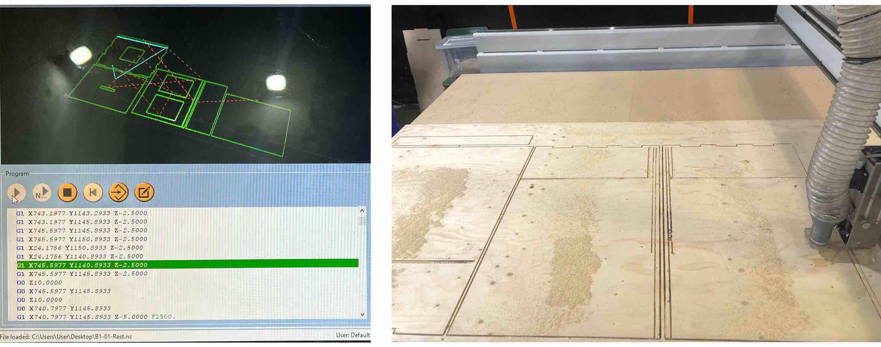
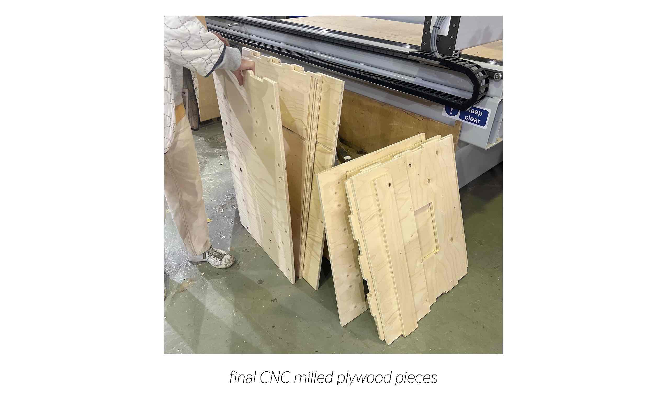
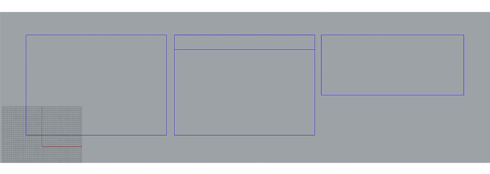
CNC
Edits we made in RhinoCAM:
- setting the stock to the dimensions of the plywood board: 15mm, 2400x1200mm
- arranging the pieces we need for optimum use of the board (they need to be spaced at least 16mm a part to make sure the tool has enough space to pass and enough is left to prevent the cut pieces pupping up)
- the rounded tool will not allow for hard inside corners so these will need to be sanded post-mill
- In the places that interlock, increase the size of the negative parts by 0.4mm on each side (0.2 mm is good for something you will perminatly lock together, we want ours to be removabe so we use 0.4)
 CNC File
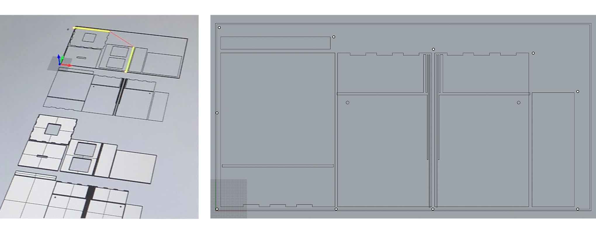
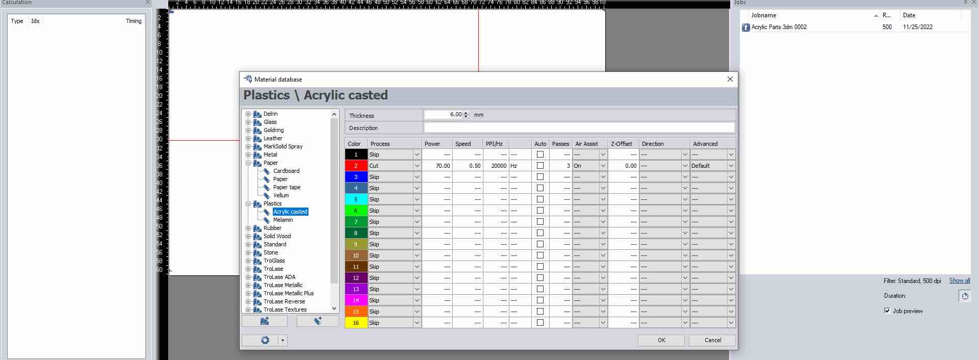
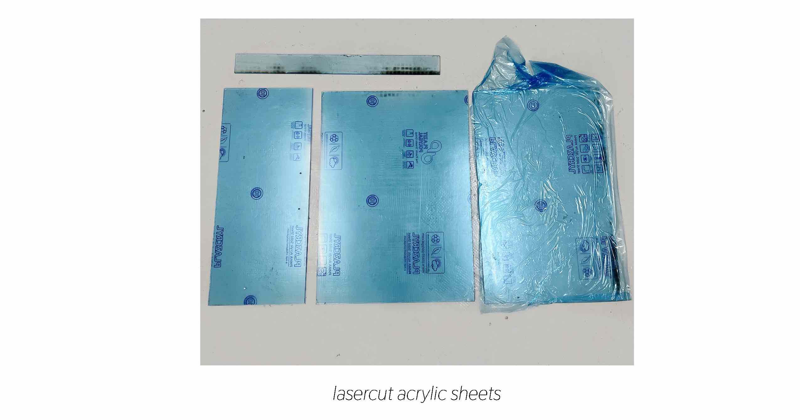
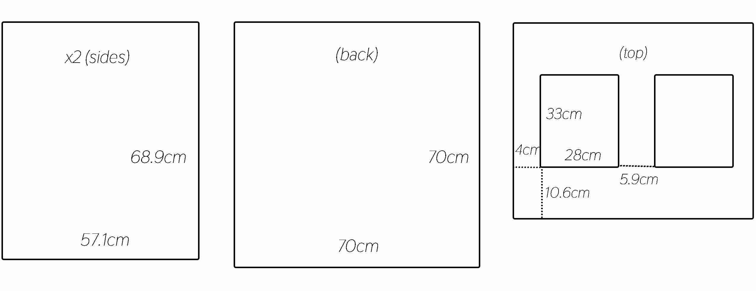
Laser Cut
File 3
Material: Acrylic
Cut: Red
P: 6
S: 0.5
F: 2000
Passes: 3
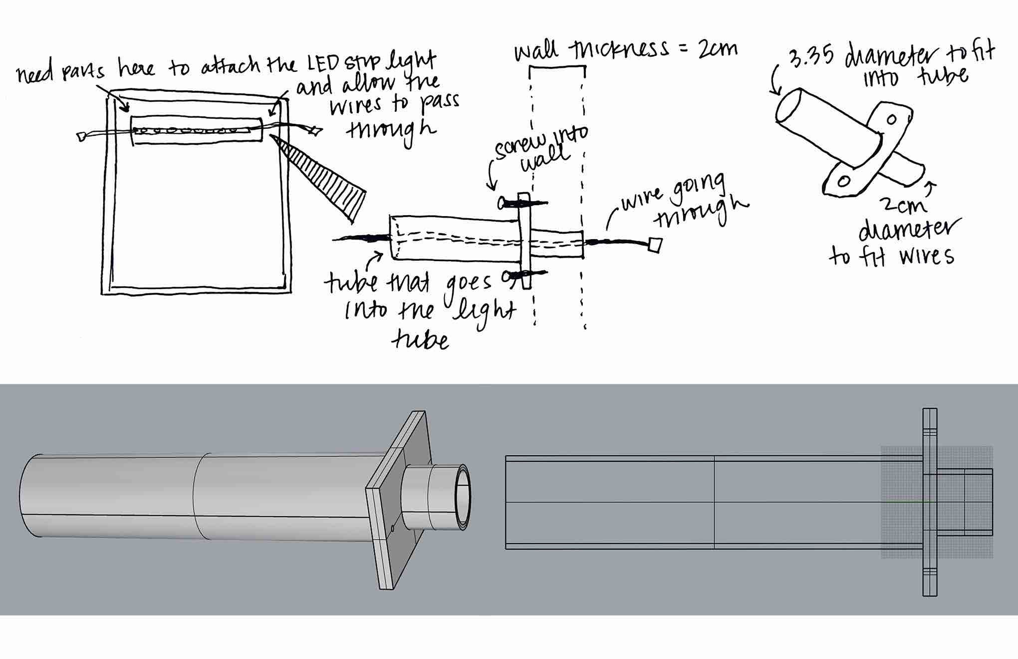
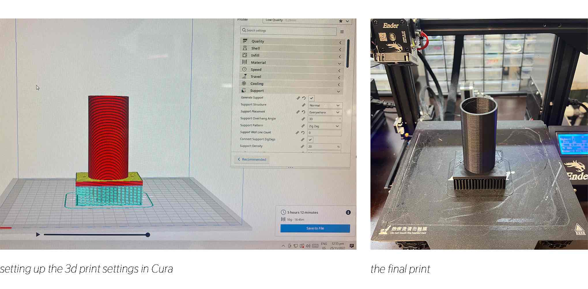
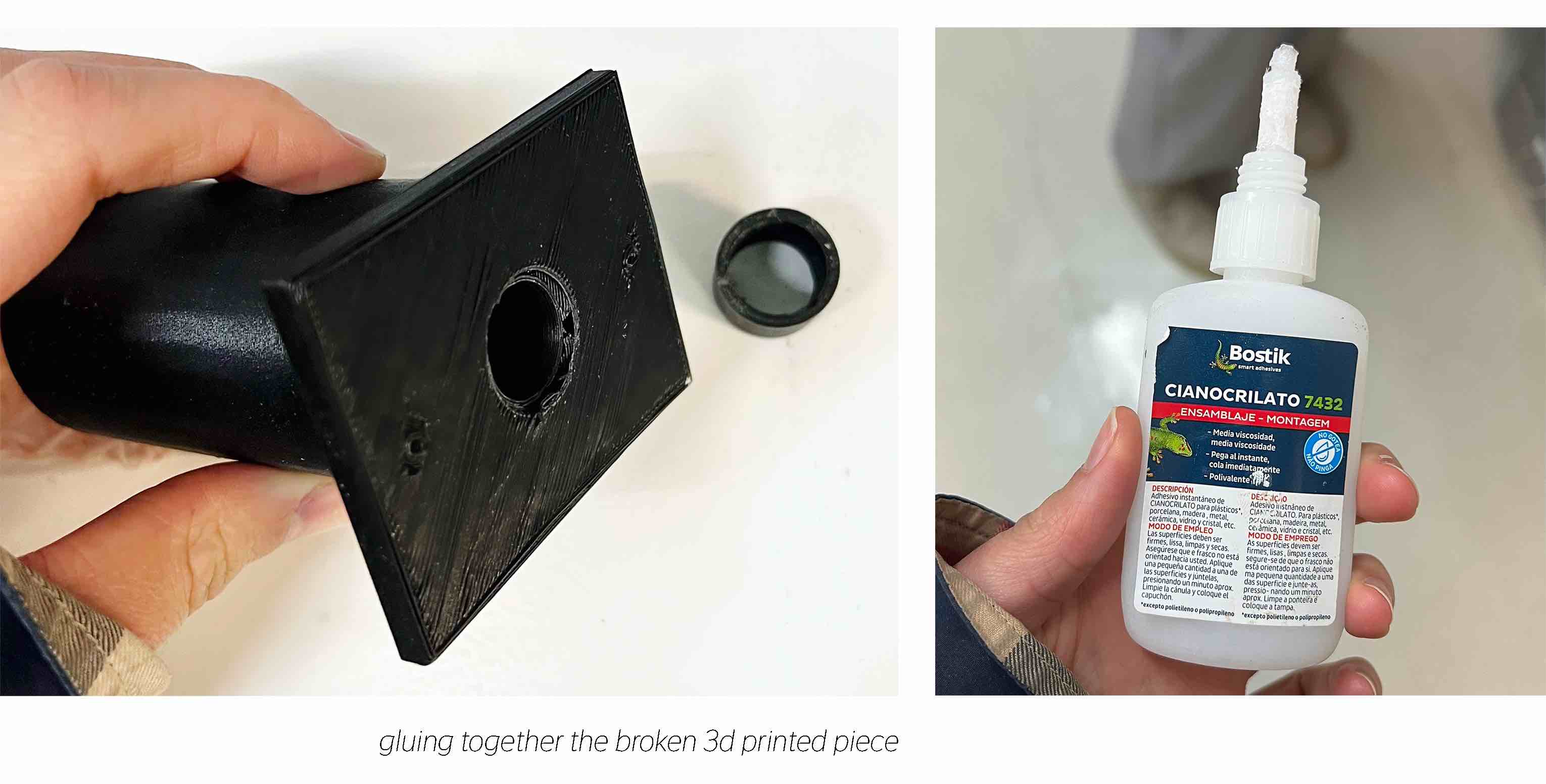
3D Printing
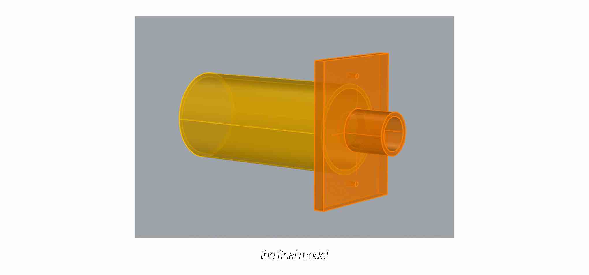
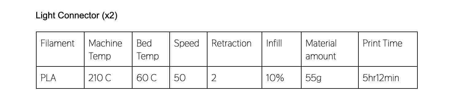
We needed a solution to secure the light in the back of the cabinet in the most sanitary way. So we needed a plastic part that is easy to clean and allows the wires for the light to pass thorugh the box without being exposed to the air inside the box. We dedided to make a custom piece that we could 3d print.
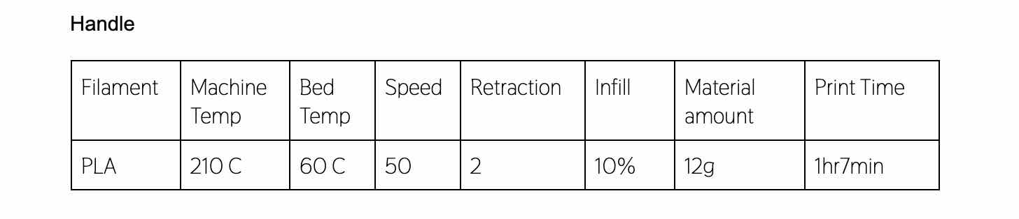
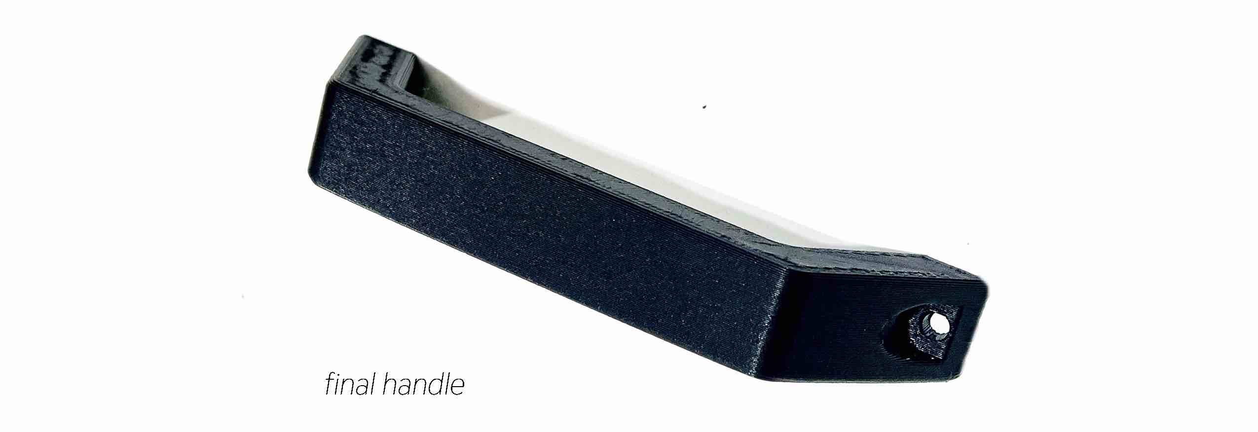
We also printed a simple handle to attach to the front of the plexiglass so it can be lifted easily.
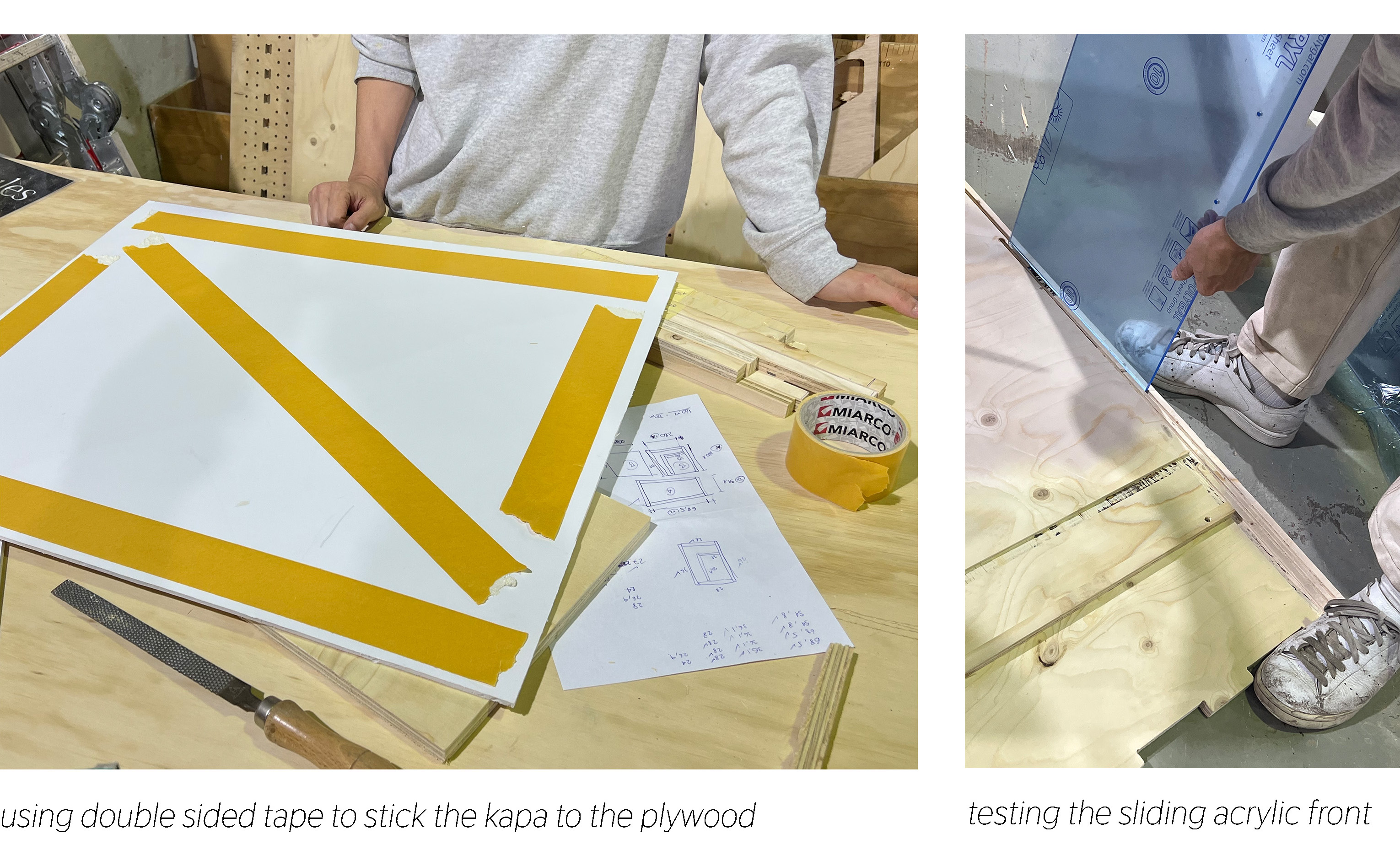
Cutting Kapa and Wooden Frames
We cut the Kapa sheets ourselves because they cannot be laser cut or cnc milled, but they are easy to slice with a blade. Working with this material we realized it is not that good for our flowhood because it can be punctured and bent easily, but we will use it for this version because it can always be replaced as we adapt and better the machine.
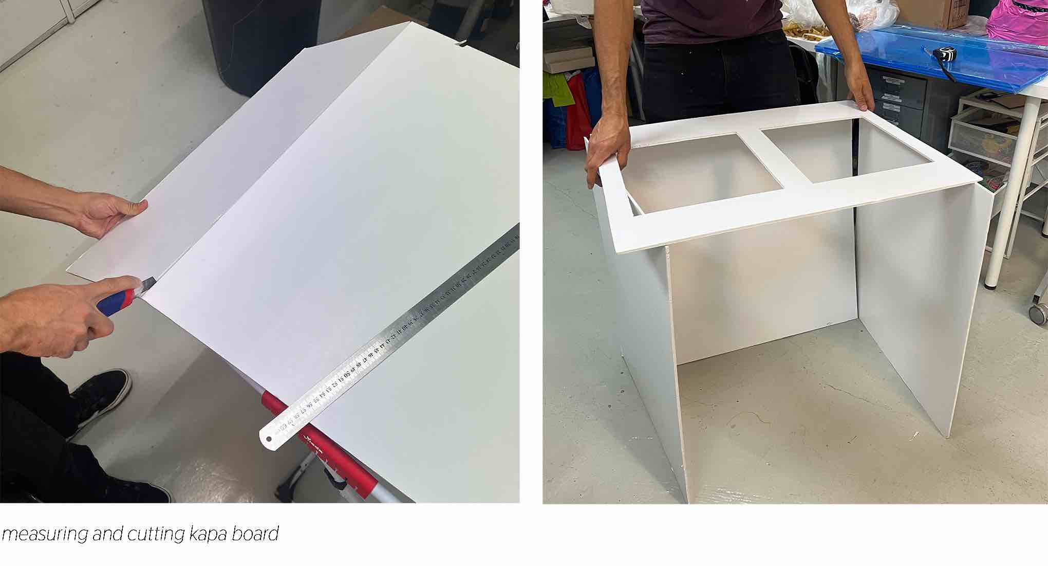
Then we needed to cut frames from plywood to surround the fan and filters.
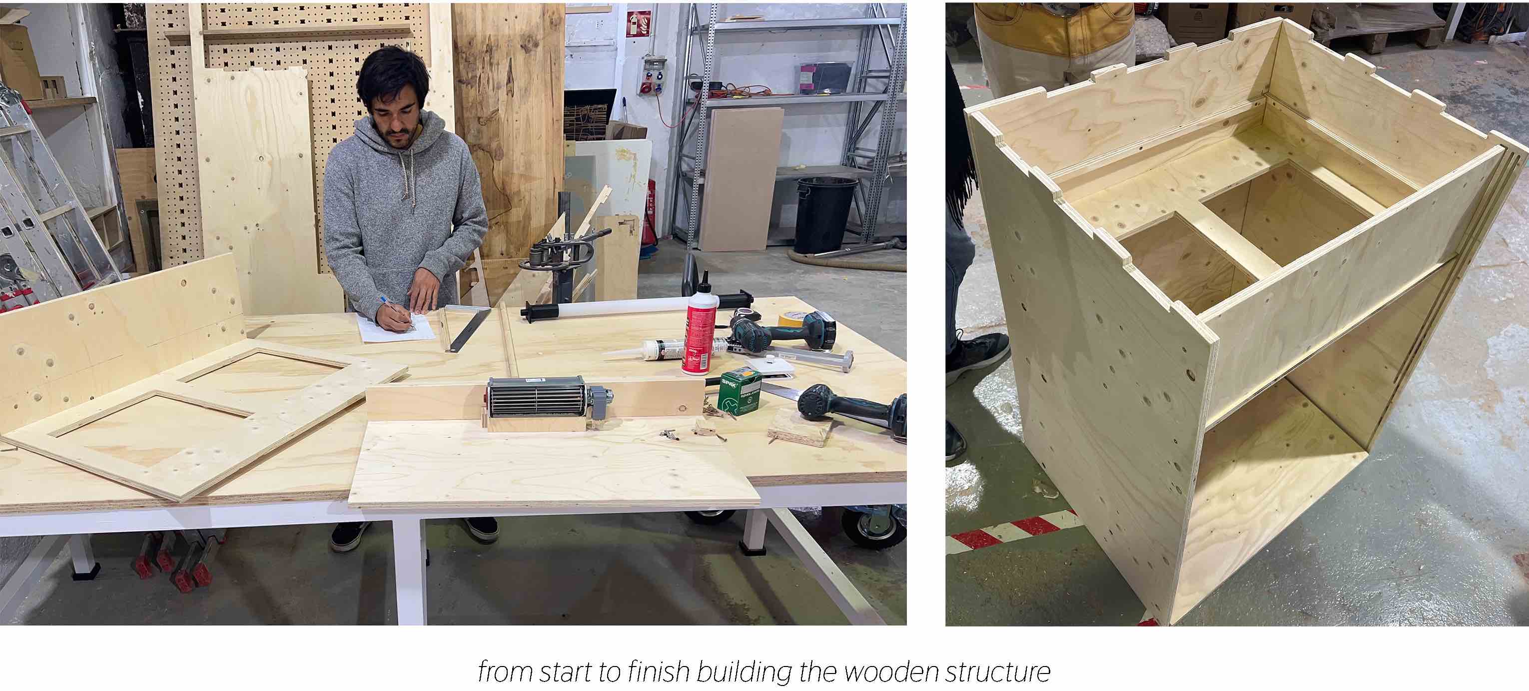
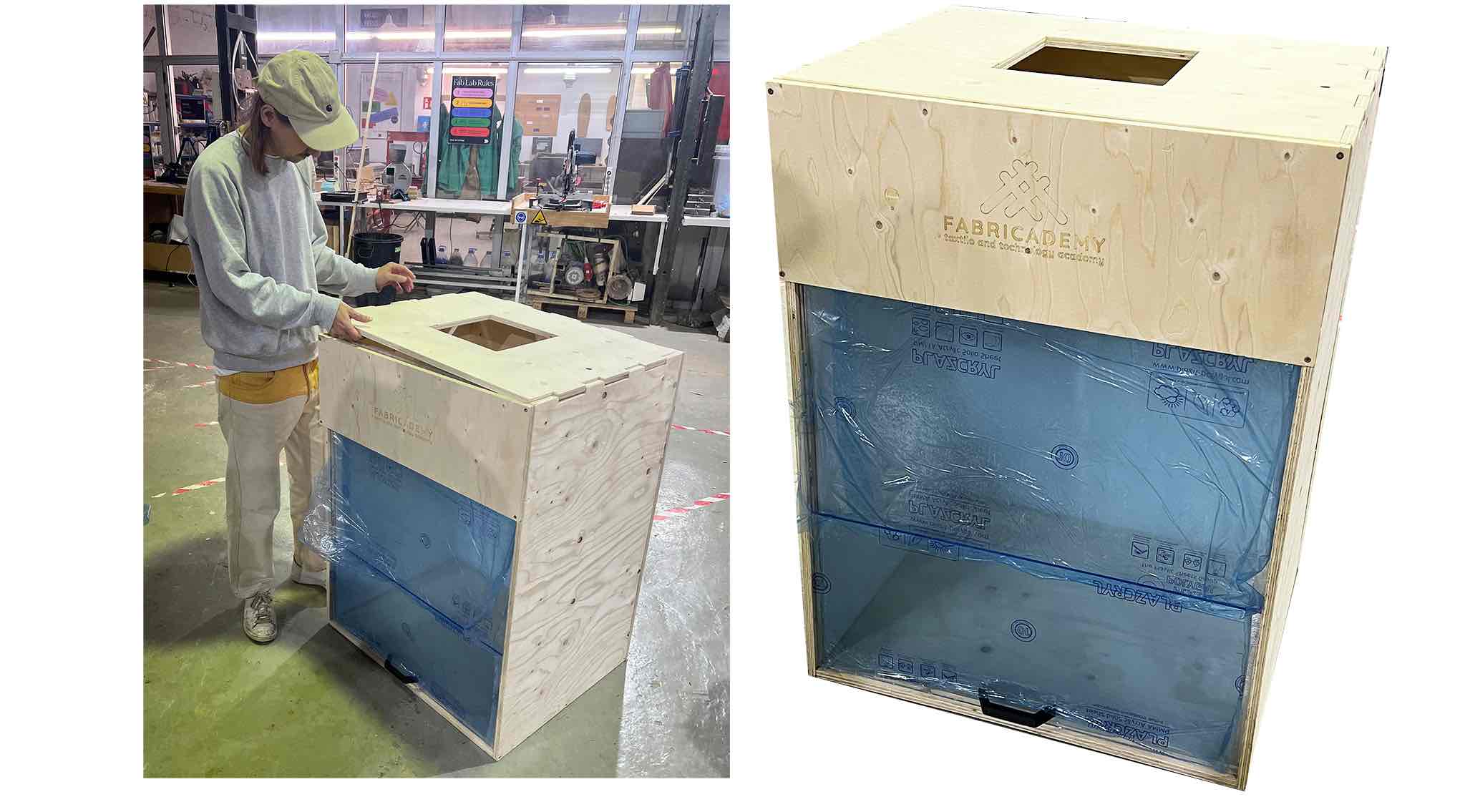
Assembly
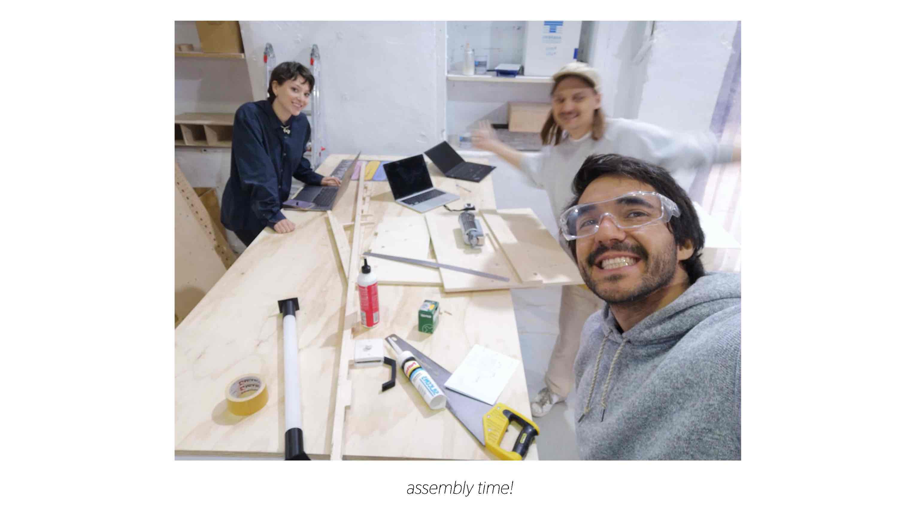 Steps for plywood assembly:
- Test all the junctions of the parts (plywood to plywood [removable top, walls in canals] and plywood to accesory [light holders in the hole, acrylic sliding front]) and sand if neccesary.
- After as few trials we found it best to start with one side wall and attach it to the perpendicular chamber roof that holds the filters.
- Join the wood in the canal by hammering it in and then screw.
- Add the second side, then the back piece.
- Slide in the acrylic sheets to the front in the canals, then screw in the bottom of the box.
 Challenges:
- Unfortunatly, one of the 3d printed light holders broke when we tested it in the plywood hole it fits into ~ make sure to add necessary tolerance and sand holes and joints to make them smooth. Luckily, the glue held and we were able to insert the light.
- We had trouble with the acrylic sheets fitting into and sliding in the plywood canals - we found it was easier to sand down the acrylic pieces rather than the wood.
- Our bottom acrylic piece was 2mm too big and needed to be sanded with the electric sander as well.
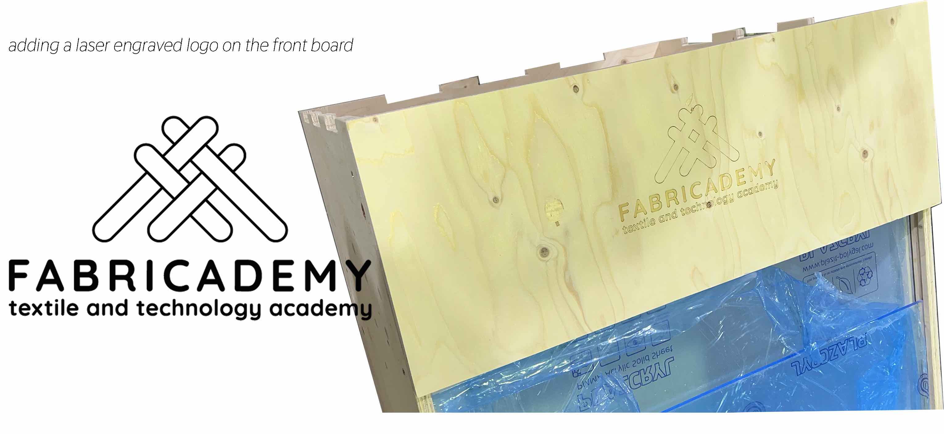
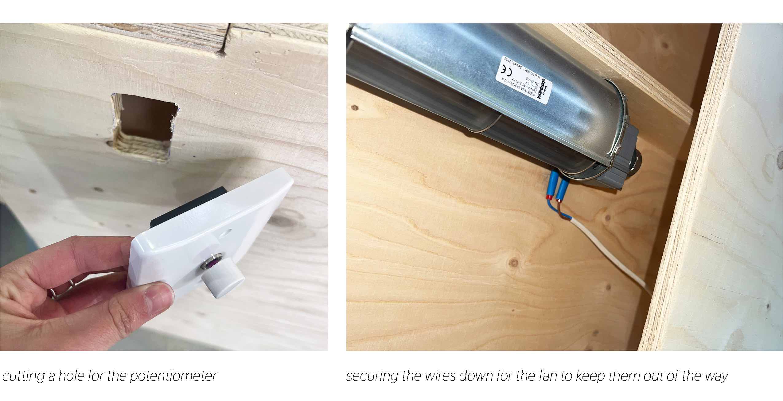
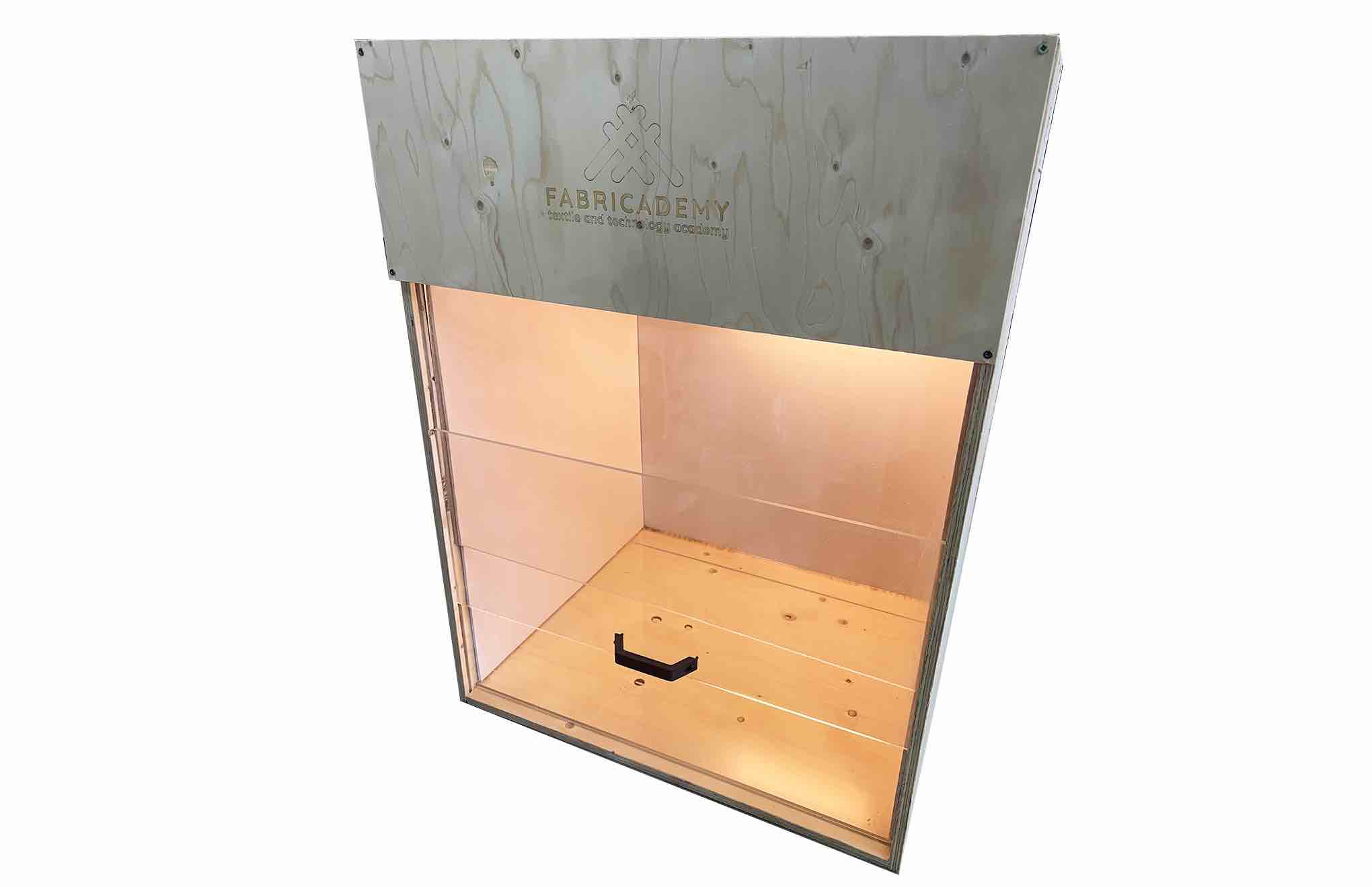
 We added a laser engraving to the front board to rep the fabricademy logo, secured the fan inside the chamber and added the light in the workspace. We added the potentionemter and wired the fan. The electronics are not too complicated because they are all connected to an outlet. We are still waiting on the filters to arrive. Then we will put those in and silicone-line all of the cracks.
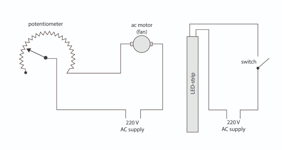
Electrical Work
Using the guide on the potentiometer manual we understood the simple AC supply circuit to connect the fan and dimming potentiometer.
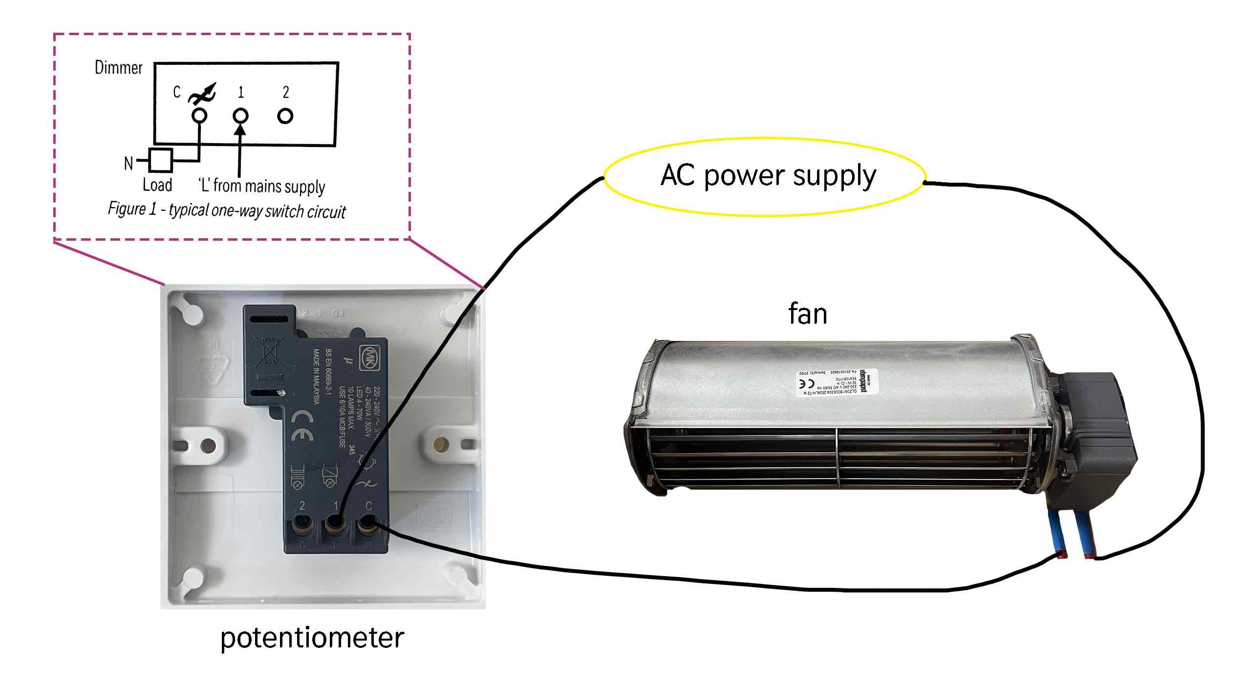 Here are the schematics for that circut, and the switch circuit that controls the light.
Final
Test
Cleaning Procedure
Flow Hood Operation
Tips and Safety for Using a Laminar Flow Hood:
- Disinfect and, depending on the activity, run the flow hood for a bit after turning it on.
- Follow typical lab dress protocol when working in the hood and follow proper aseptic technique.
- Remember that it will not protect the user from contaminates, it only protects the items under the hood.
Next Steps and Conclusion
- get the potentiometer working correctly
- install the filters once they arrive
- seal all the cracks with silicone
- run a candle smoke test to visualize the airflow
- try an airflow simulator software with the model
- eventually replace the Kapa foam with a better material
- eventually add a UV light for sanitation
- Eventually add another motor