5. E-textiles
My disco pears with sound and light, a great duo!
My bend sensor connected to Arduino
My stroke sensor turned into a swatch
The week started with a presentation of Liza Stark about e-textiles, which left me both inspired as well as dazed. It's a whole new world! Our focus was on developing a digital and analog sensor, program them with Arduino, and turn them into swatches. An assignment which requires some theoretical explanation.
Background and definitions
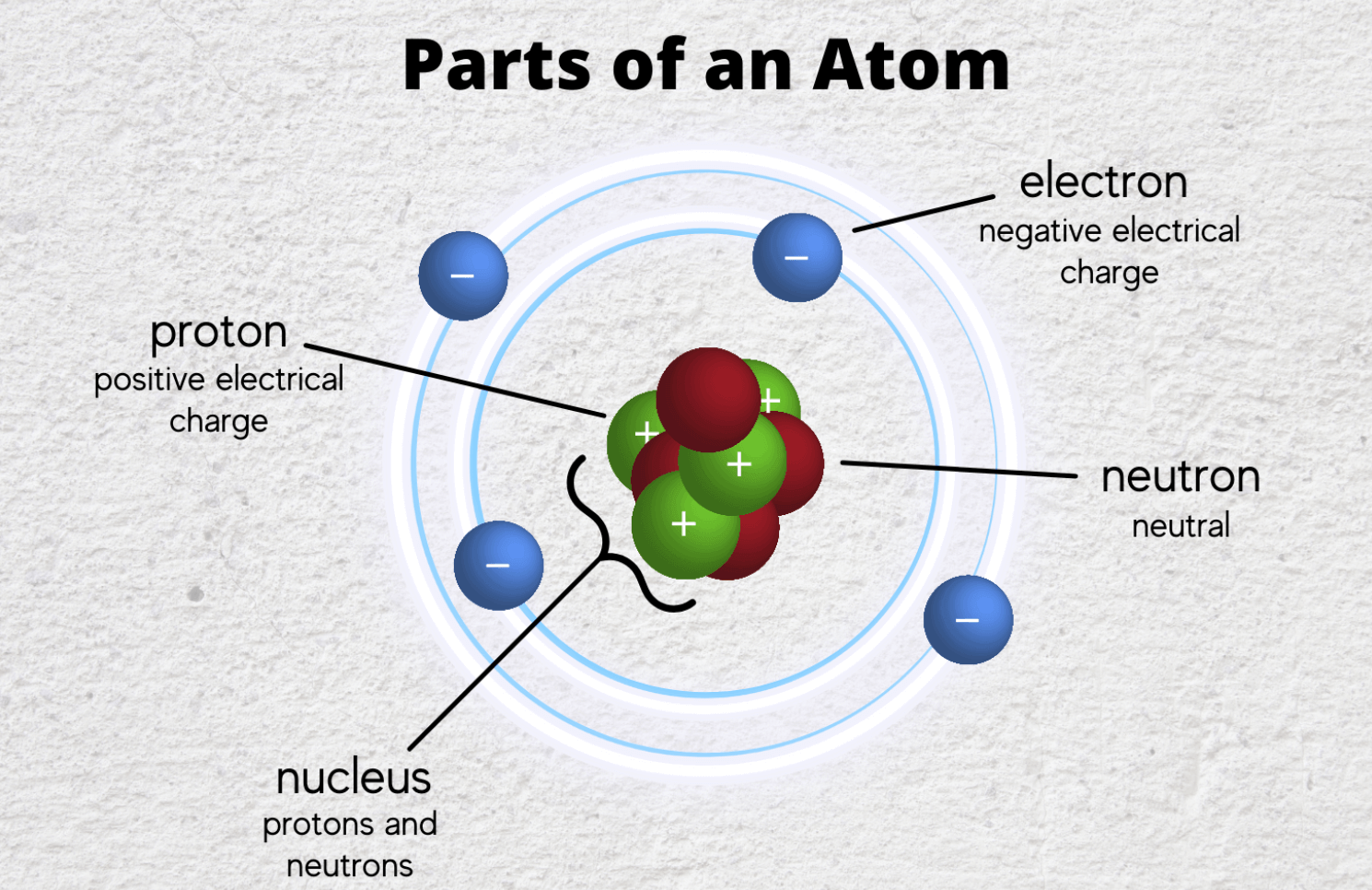
An atom is a fundamental piece of matter. (Matter is anything that can be touched physically.) Everything in the universe (except energy) is made of matter, and, so, everything in the universe is made of atoms.
An atom itself is made up of three tiny kinds of particles called subatomic particles: protons, neutrons, and electrons. The protons and the neutrons make up the center of the atom called the nucleus and the electrons fly around above the nucleus in a small cloud. The electrons carry a negative charge and the protons carry a positive charge. In a normal (neutral) atom the number of protons and the number of electrons are equal. When the number of electrons and protons get unbalalanced, the atom becomes negatively or positively charged.
We are going to leverage dynamic electricity, that is the electricity resulting from electrons moving continuously on a physical path. Such a closed loop path is called a circuit. A circuit must contain a power source, traces, and a load.
Some definitions from Liza's and Emma's presentation:
- Any material that is conductive can function as a trace.
- Electrons flowing through traces is a current, measured in Amperes (A).
- A power source needs to start the electron movement through the loop and this is usually a battery.
- Inside a battery there are chemical reactions that make one side of the battery positive and the other one negative.
- The negative side is called ground (-).
- The positive side is called power or VCC (+).
- The capability of the battery to move the electric charge is called voltage, measured in Volt (V).
- When a trace is directly connected from ground to power, a short-circuit results (dangerous!).
- To avoid a short-circuit, a load needs to be included in a circuit.
- A load is any component that consumes current, like light, heating pad, motor, speaker, a sensor, or a resistor.
- Resistors impede a flow of current and impose a voltage reduction.
- Any material with poor conductive characteristics can function as a resistor.
- The resistance of a resistor is measured in Ohms (Ω).
- With a multimeter the current, voltage, and resistance can be measured.
- Ohm’s Law defines the relation between current, voltage, and resistance - V = I x R.
- A LED is a lightsource, the current flows only from the Anode (+, long leg) to the Cathode (-, short leg).
- The breadboard is a physical support for making temporary circuits and prototyping.
- Arduino is a programable microcontroller, we will use the simple version Genuino Uno.
- With software code can be written to upload to the Arduino microcontroller, so that the microcontroller performs tasks.
Soft sensors
Soft sensors are little devices made up of conductive and/or resistive material, of which the interaction in a circuit impacts or generates an electric signal.
There are two types of sensors. The digital and the analog sensor.
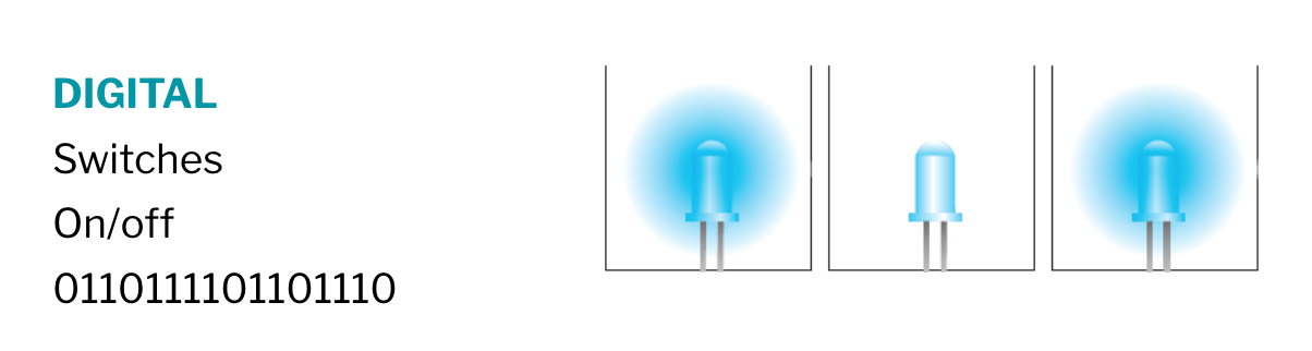
Digital sensor
A digital sensor or switch is made up of two conductive parts that can mechanically touch each other. When they touch each other, we say that the switch is closed, otherwise it is open. In effect, it is an on/off button.
With the multimeter in continuity mode, the current of a digital sensor can be measured.
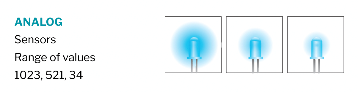
Analog sensor
An analog sensor is a resistor but its resistance is not fixed. In effect, it is a variable resistor!
With the multimeter in the resistor mode, the resistance of an analog sensor can be measured.
Inspiration
I love the dresses of the project Stymphalian Birds from Audrey Briot. Upon touch, feathers attached to the dress, provide etherical sounds. The feathers have been made conductive through a polymerization process, called Polysense. It's a pretty technical approach, but the end-result is dreamy.
One way or another, this feather project, reminded me of a book I just red. It is called "De vergeten ecosysteemdienst van bomen" from Karolien van Diest. The book discusses trees as an energetic entity. Yes, trees supply wood, fix CO2, capture particulate matter, form islands of fertility, milder the climate, store water, and they do so much more for the earth and people. But trees are also generating geo-phyto-electrical currents which stream with the rhythms of day and night, of the seasons, and of the moon. By electric currents through the soil, trees are even interacting with each other. It seems odd, but those currents have been measured and researched.

The theoretical physicist Carlo Rovelli says it beautifully:
We are made up of the same atoms and lights signals as are exchanged between pine trees in the mountains or stars in the galaxy. A handful of types of elementary particles, which vibrate and fluctuate constantly between existence and non-existence and swarm in space even when it seems there is nothing there, combine together to infinity like the letters of a cosmic alphabet to tell the immense history of galaxies, of sunlight, of woods and of the smiling faces of the young at parties.
My plan for the week is to combine fabric with some tree branches, creating swatches that bring to life the energy of trees. Unfortunately we do not have the ingredients in the lab for the Polysense polymerization approach. So I have to make it work in another way.
This week's work
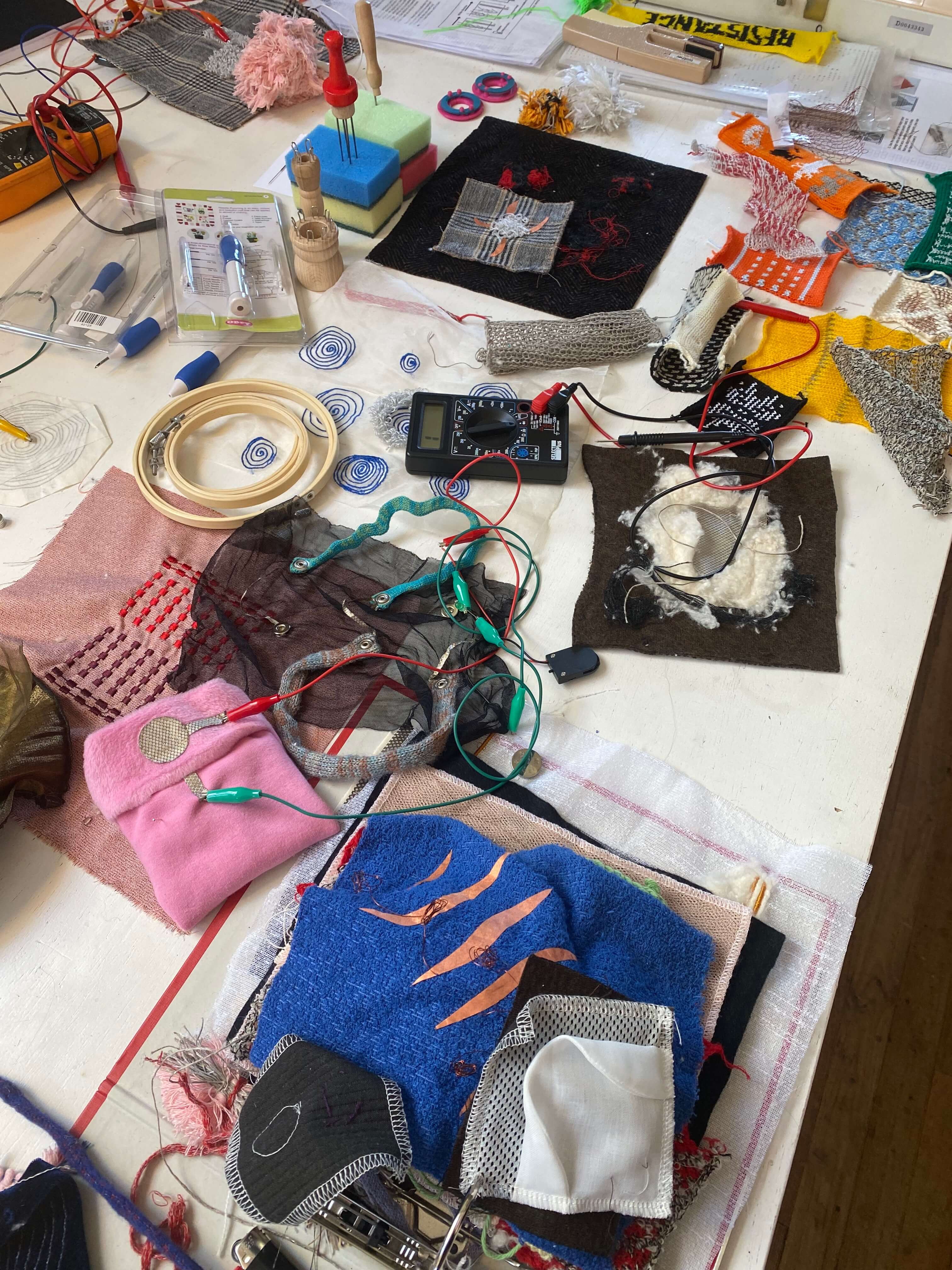
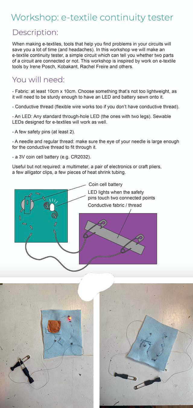
Continuity tester
Before we started with our sensors, we first made a continuity tester, with which we could quickly test the sensors and circuits we were going to make.
Prototype
Before going more complicated, I first wanted to do a little prototype. I aimed to build a simple digital sensor from some leaves and gold thread, called 25% Metal Egypto Color Gold Gimp. I borrowed two little branches from a plant in the lab. On each branch I stitched one leaf with some gold thread. I wired the threads from the leafs to the bottom of the branches.
I connected one of the gold wires with the ground on my continuity tester and the other gold wire with power. And sure, when the two leaves kissed each other, the switch made a closed loop, and my little trees fired up a LED lamp.
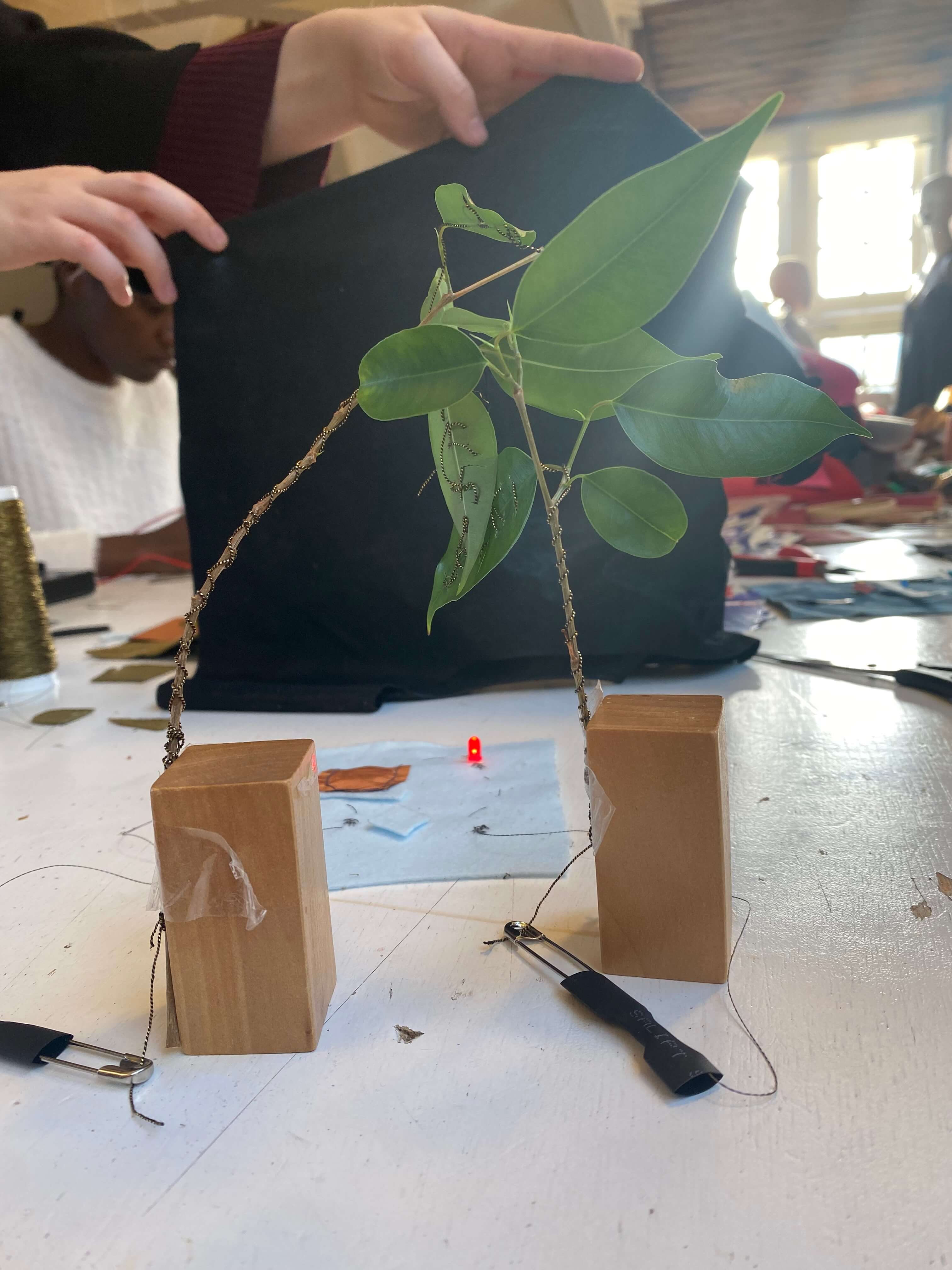
My mini trees were actually pretty cute, but I felt I had mistreated the branches by sewing large holes through their leaves. The next effort had to be better!
Digital sensor
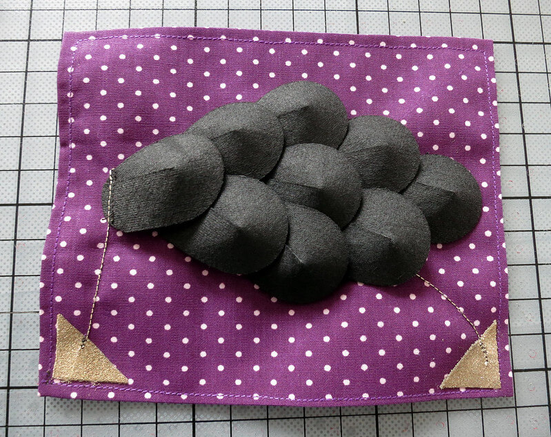
Since we had pruned some pear trees in our garden, I took some pear branches with me to the lab. I wanted to incorporate them in my sensors.
First I made a bigger version of my little prototype of the day before.
I placed one pear branch in an empty bottle. This time I used conductive fabric tape. I stuck the tape on several leaves and also wrapped the tape from top to bottom around the branch. I made sure the tape on each leaf was in contact with the tape around the branch. The tree was conductive.
Then I took a second branch. I used copper-colored conductive fabric and wrapped the top of the branch with this fabric. I bound it in place with some radio conductive thread and wired this thread all the way around the branch to the bottom. I connected this thread with a ribbon of copper-colored conductive fabric. The stick was conductive.
I connected the tree and the stick to the multimeter in continuity modus and when I touched with my stick the tree, I got proof the circuit functioned correctly.
When I connected the same circuit to my continuity tester I could switch on the LED light by poking the stick through the leaves of the tree.
Mission accomplished. I had my digital sensor.
Pear branches as digital sensor
Analog sensor
On the website Kobakant I had seen a so-called Fish scale sensor.1 The description for this sensor was as following:
When laying flat, electricity flows through series of scales from one end of the sensor to the other, adding the resistance of each scale. This is similar to potentiometer or slider. When bent inward, the scale touches each other in shorter distance resulting the resistance across to become lower. When bent outward, the scale touches further away, or dose not touch at all, resulting higher resistance or discontinuity. The reading of this sensor is not smooth, but it gives a unique combination of analog sensor (slider) and digital sensor (contact switch) affect.
My plan was to use the leaves of my remaining pear branches. Cover the bottom of the leaves with some Eeonyx non-woven conductive textile and stitch those leaves in a scale form, on brown leather. In that way I had a visualization of "rustling leaves" as a sensor.
Just when I made my first moves, Bea came along to take a look and she made a remark that completely changed my track.
She said:
"Well, when leaves have an electric current running through them, you should be able to measure the resistance."
And that's what I did!
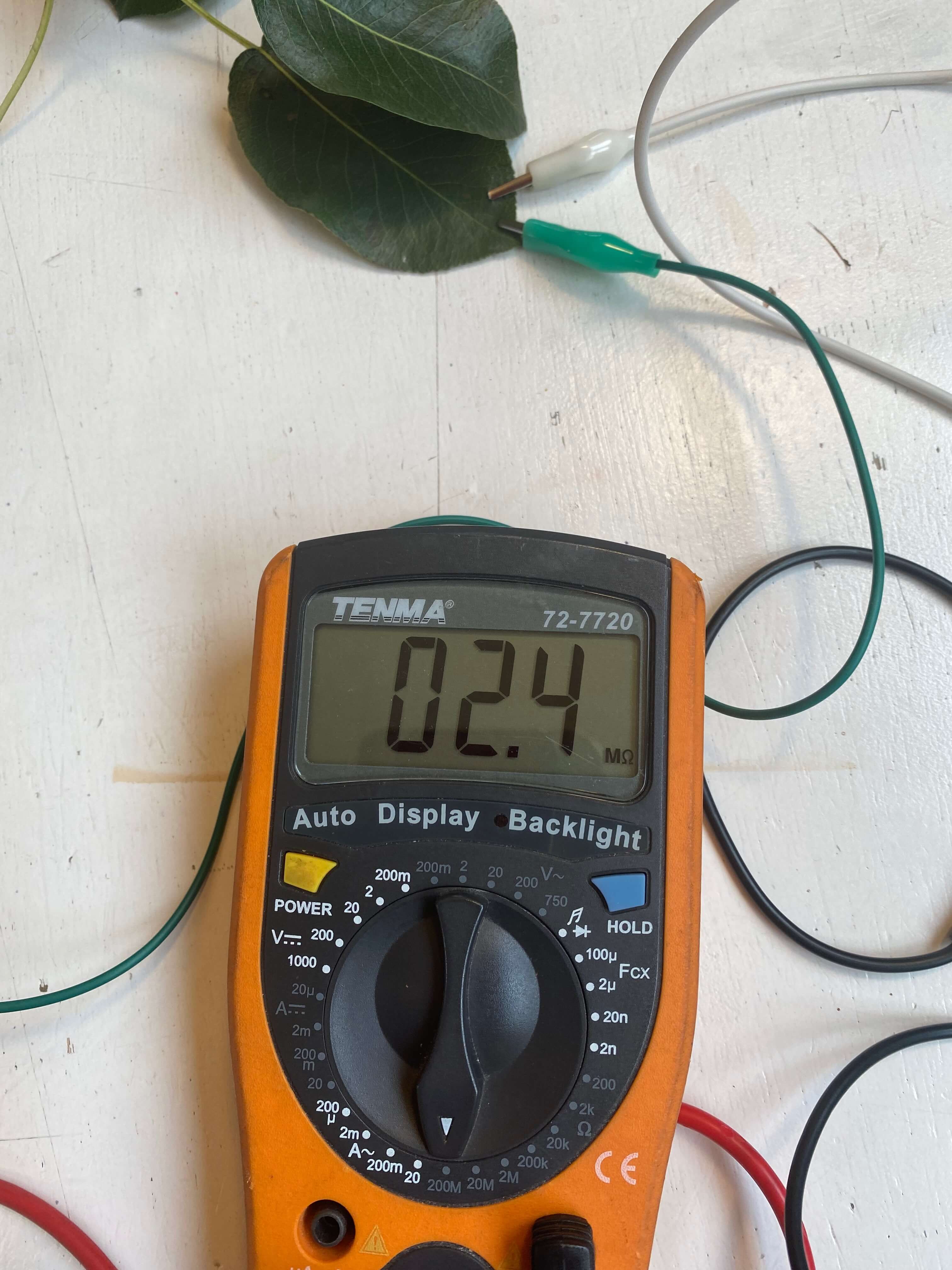
I connected two alligator clips to my multimeter, and the other ends to arbitrary leaves on my remaining pear branch..... And was highly dissappointed when the multimeter gave an overload reading.
I decided I had to do some research first. Many articles were available about the resistance measurement of plant tissue. In one scientific article describing the resistance measurement of maize leaves, it was stated the resistance was in the range of 10 MΩ and went up with increasing distance of the electrodes.2
Because of the article I realized I had to change the scale of my multimeter to 20 MΩ. Once I had done that the pear branch began to talk to me!
I first varied the distance of the electrodes. And indeed, when the distance became larger the resistance increased significantly.
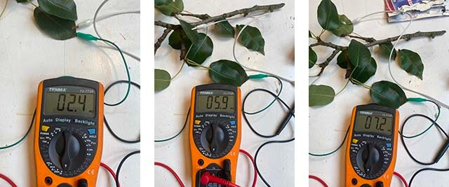
While shining light on the leaves, the resistance increased as well. Also moving and shaking the branch altered the resistance. But what I liked most? When I touched and stroked a leaf, and gave it some love, the pear branch responded by increasing the resistance again.
Love and tender care versus resistance
It was clear from those experiments. I didn't need to add any fabrics, tapes, threads or paints to this branch. Nature had provided me with the best analog sensor.
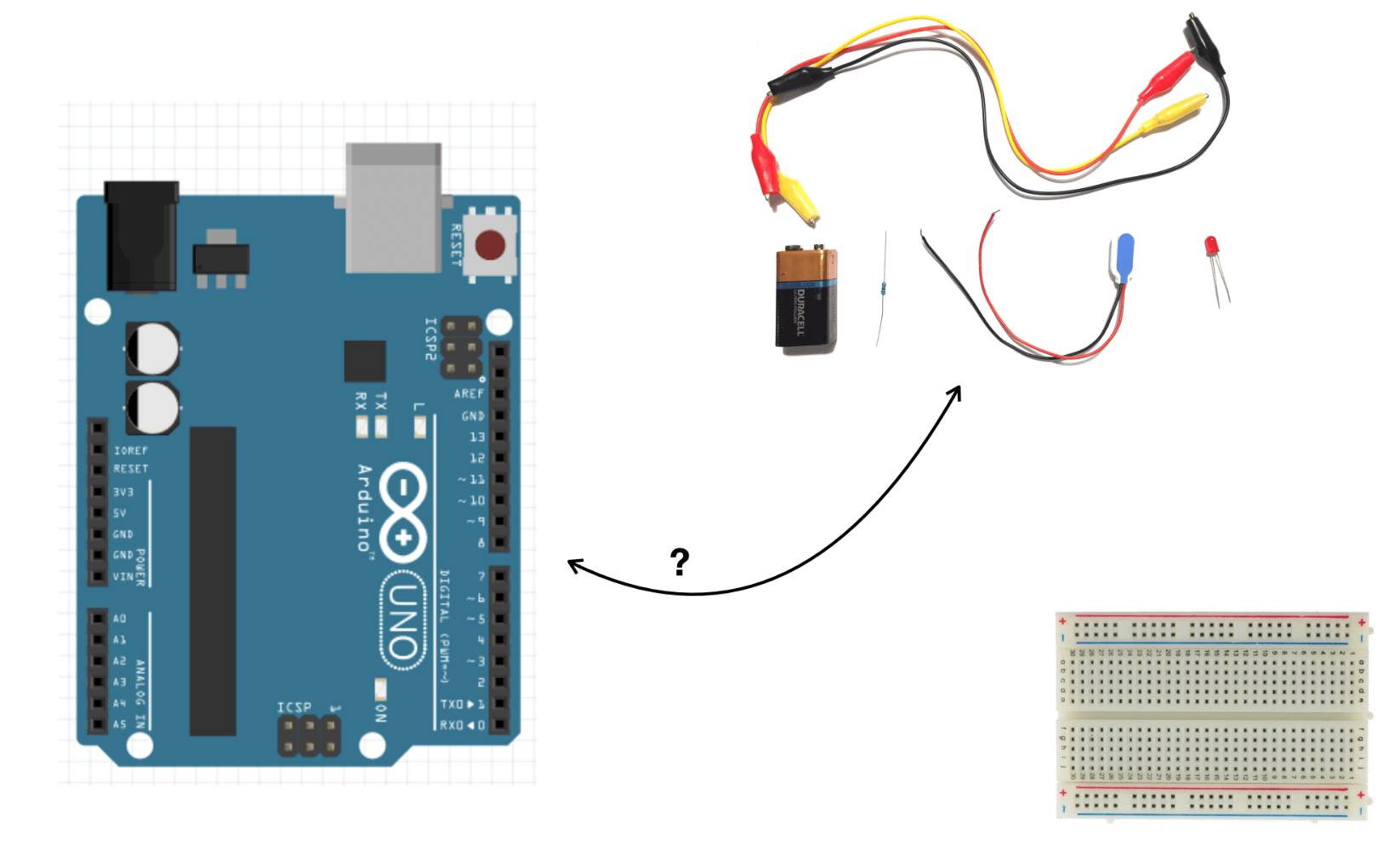
Working with Arduino
Arduino is an open-source electronics platform based on a hardware board (Genuino Uno) and software. Arduino boards are able to read inputs and turn it into an output. You can tell your board what to do by sending a set of instructions to the microcontroller on the board. To do so you use the Arduino programming language and the Arduino Software (IDE). With help of Arduino you can build and test circuits (prototyping). Instead of soldering the circuit components, a breadboard is used to plug in the various components of the circuit. So Arduino is ideal for testing how you could apply your sensors.3
Connecting Arduino to the computer
The first thing is to test if the environment works.
The steps are as following:
- I connected the microcontroller via an USB port to my computer.
- In the menu I opened "Examples" and then "Blink".
- Then in the menu I opened "Tools" to select the port and Board.
Once these steps are performed, the LED light on the microcontroller should blink. But here I encountered a problem. My computer didn't recognize the microcontroller, hence I couldn't select the port and Board. To troubleshoot, I first changed the USB port. That didn't make a difference. Then I unplugged the microcontroller and tried the same procedure with another Arduino board. This did the trick, because I was able to select the port and Board and the LED on the microcontroller started blinking.
Arduino board blinking
Playing with my analog sensor
Reading my analog sensor
The first thing I wanted to do was to read my analog sensor, in other words I wanted to get data out of my pear branch. Arduino boards contain an analog to digital converter. This means that it will map input voltages between 0 and the operating voltage into integer values between 0 and 1023. For this action you have to build a circuit and then write the relevant code which you upload to and run on the microcontroller. In my case my analog sensor was the pear branch. In order to include the branch in the circuit, I connected two alligator clips close to each other on one pear leaf. The other end of the aligator clips I connected to the pins of two little wires, which could then be pinned in the breadboard. In order to see the live data, you can open the serial monitor, a screen which shows the data running.
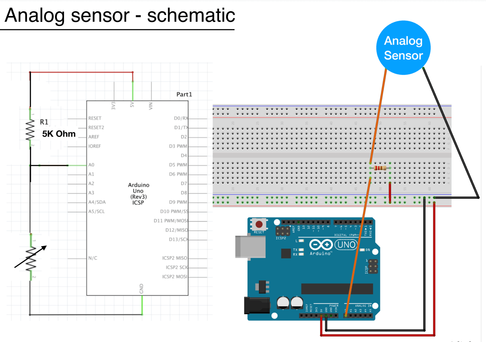
I wrote my code, and uploaded it, then I opened the serial monitor. Unfortunately, the serial monitor only showed rows and rows and rows of the number 1023. I was looking at an overload reading. After some research on the internet it became clear that the resistance of the analog sensor and the resistance of the resistor on the board should not be too different from each other. From my previous tests I knew that the resistance of the pear leaves (dependant on the distance) was in the range of 2-10 MΩ. But the resistor on the board was an ample 5 KΩ. So I changed the resistance on my board with a 10 MΩ resistor. With that action I was able to perform the analog read.
Reading my analog sensor
Translating the analog read in resistance
Now I had the analog reading of my pear branch, I could go a step further. With help of the analog read, I could map the resistance of the pear branch. In effect you turn the Arduino microcontroller in an Ohm meter. The circuit is really simple. All you need is the resistor you want to measure (my pear branch), and another resistor with a known value (I used again a 10 MΩ resistor). You program Arduino to measure the voltage between the two resistors and then with help of Ohm's law the resistance of the unknown resistor can be calculated.4
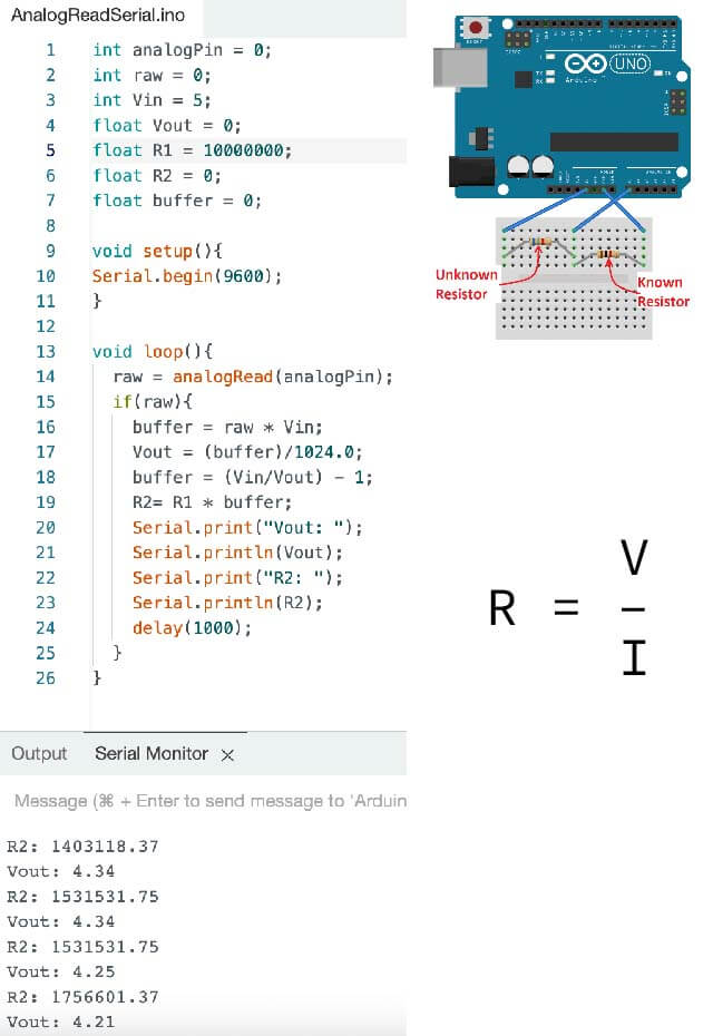
The values for resistance that Arduino measured varied between around 1-3 MΩ. I doublechecked the validity of those numbers by connecting a multimeter next to the aligator clips on the same leaf. And the values on the serial monitor were in line with the values the multimeter showed.
Calculating the resistance
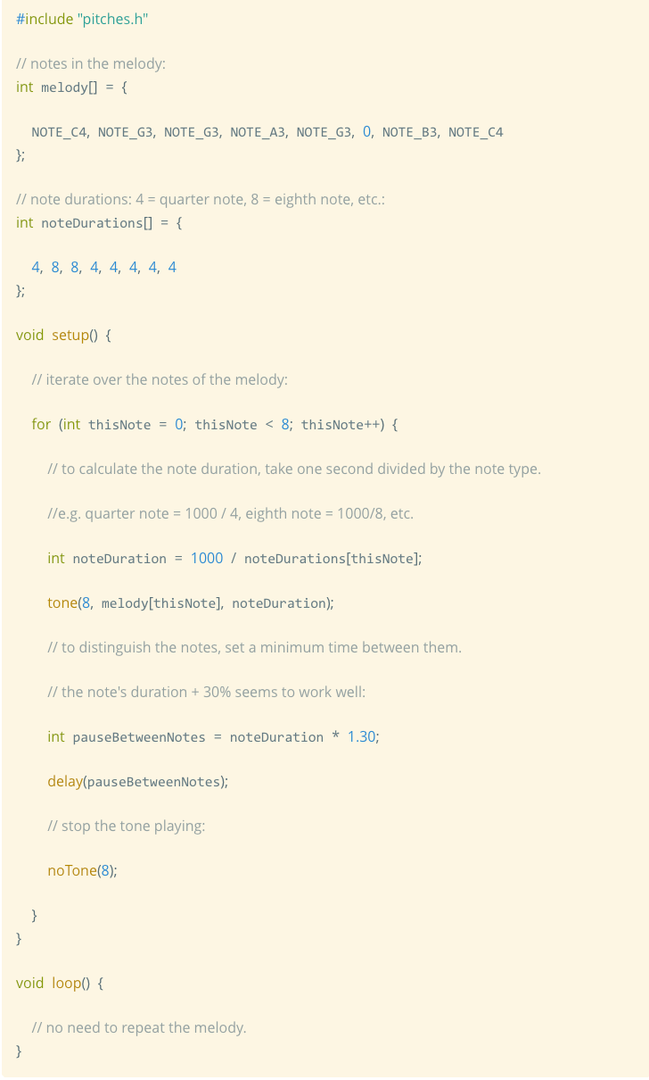
Converting resistance into sound
I decided I wanted to convert the resistance into sound. How nice it would be if my pear could make itself heard! We found a little 8 Ω speaker. Before I tried to control the speaker by my analog sensor, I first needed to test the speaker and the code for making sound.5
The steps are as following:
- I didn't change anything to my previous circuit, but added the speaker by hooking it up to output pin 8 and to Ground.
- Then I created a new tab in Arduino by clicking on the button just below the serial monitor icon and choosing "New Tab".
- I called this tab "pitches.h".
- On this tab I copied pitch values for typical notes. For example, NOTE_C4 is middle C. NOTE_FS4 is F sharp, and so forth. This note table was originally written by Brett Hagman.
- Then I copied the code for the "tone" function in Arduino in the first tab.
I choose "Upload", and my speaker started to repeat the coded melody in continuous mode.
Now it was time to combine the two codes for calculating the resistance AND for converting this into sound. But then with an if-statement, so that only when the pear's resistance peaked ABOVE a certain value, the melody would sound (I choose 2 MΩ as the threshold). In other words, the variance in resistance of my analog pear sensor would activate on and off the melody sound.6
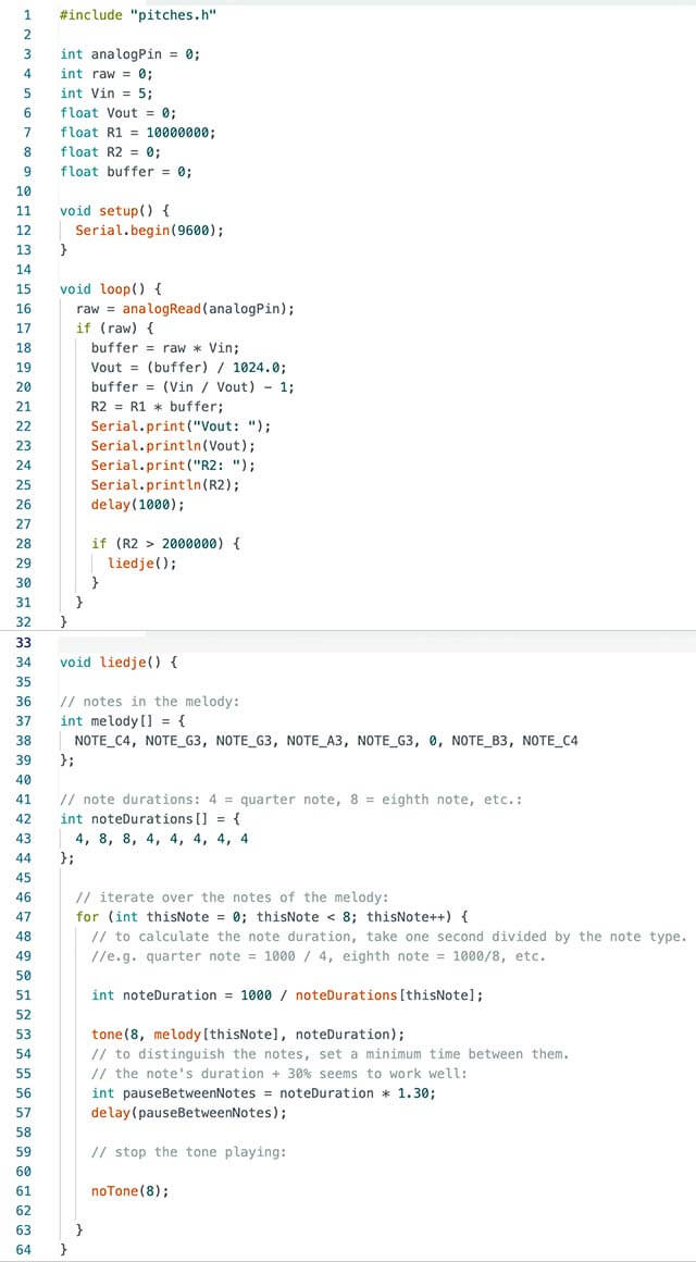
- In line 1 the defined notes in the new tab, called "pitches.h" is called.
- In line 7 I gave the value for the known resistor, 10 MΩ.
- In lines 27/28, with an if-statement I define the resistance threshold for sound at 2 MΩ.
- In lines 37/38/39 I define the notes in the melody.
- In lines 42/43/44 I define the duration for those notes.
- In lines 53 and 61 I define the output pin for the melody as 8.
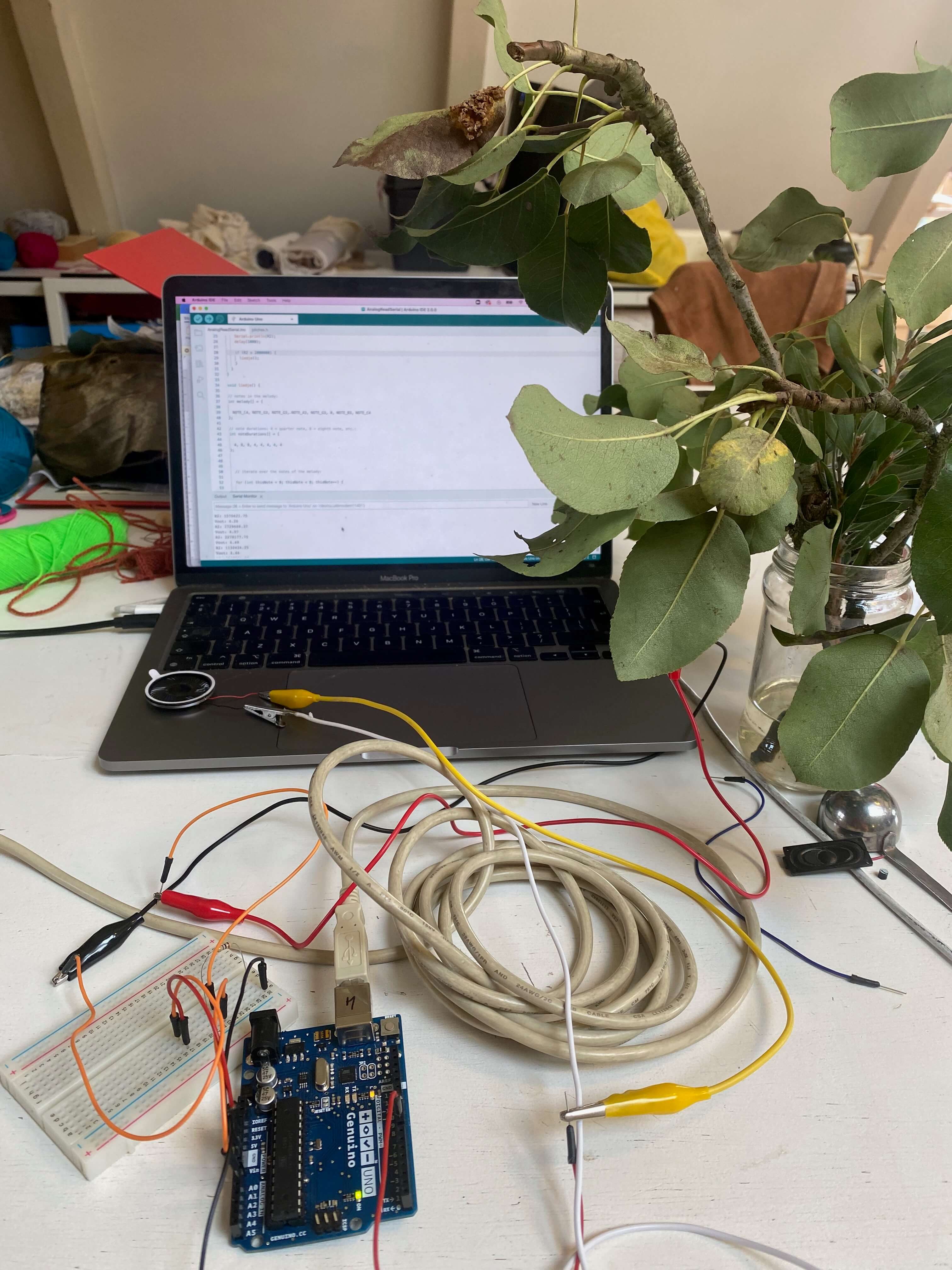
Disco pears: Integrating both my sensors into a swatch
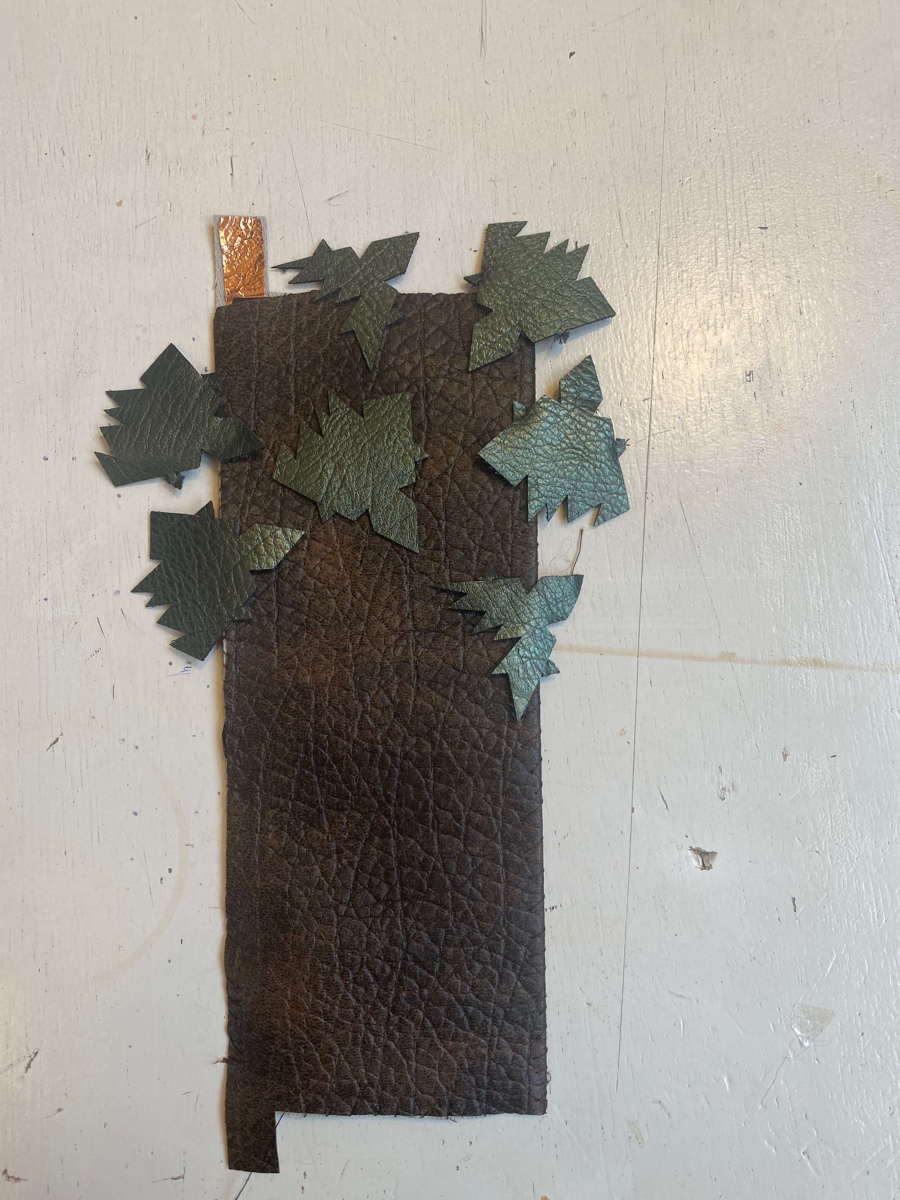
I couldn't disconnect my analog sensor from Arduino. The electric current through the leaves was simply too weak for that. So I left the analog sensor connected to the Arduino board and only dressed the pear in a sexy yellow leather outfit.
The pear branches (stick and tree) that formed my simple digital contact sensor, I integrated in a circuit with a 3V battery and a LED light. Every time I touched with the stick the leaves or branch of the tree, the LED light switched on. Also this tree got a funky brown leather dress, behind which I hid the circuit.
My disco pear swatch was ready to perform!
My disco pears with sound and light, a great duo!
Another sensor and swatch
In order to familiarize myself more with sensors and materials, I made another analog bend sensor and integrated a digital stroke sensor in a swatch.
Tree in the wind: analog bend sensor
On Kobakant the steps to make a simple analog bend sensor are explained.1
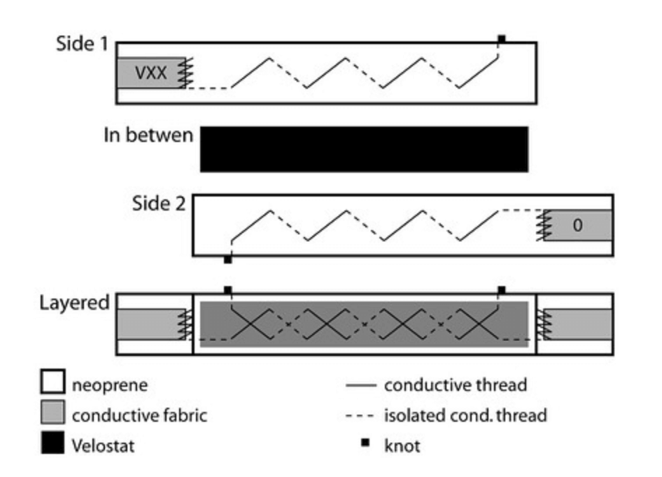
Instead of Neoprene I used leather for the outside layer. And I didn't apply conductive thread, but instead used conductive tape. For the resistant layer I used a piece of Velostat.
Also for the bend sensor I did an analog read with Arduino. The bend sensor gave a nice range of values.
My bend sensor connected to Arduino
Grass lightning: digital stroke swatch
I like the idea of touch triggering an action. So I made a digital stroke sensor which I integrated into a swatch with a 3V battery and a LED light.
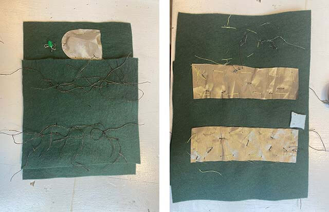
I applied some green velt as the basic layer. On the back of this I stitched two rectangles of copper-colored conductive fabric. In those rectangles I stitched conductive gold thread for the grass. On the front, from the same conductive fabric I stitched with non-conductive thread a small sack for the battery (power). With radio conductive thread I sew a trace from the sack to the LED light and then to one of the two conductive rectangles. Behind the sack I sew a connection point (ground) and sew the trace to connect with the other rectangle. I slid the battery in the sack. And although my stitch work wasn't great, once I stroked my grass the LED light switched on.
My stroke sensor turned into a swatch