8. Wearables
This week we continued with the world of Wearables. We focused on coding and moved our attention from inputs - sensors, to the realm of outputs - actuators, ranging from visual outputs, to sound and motion enablers!
Final results
First I focused on creating a circuit and the coding for a switch button (digital sensor) and a capacitive sensor.
After that it was time to play with actucators.
My swirling flower, a motion actuator
My arrow, thermochromic pigment on a heating element
My transforming flower, thermochromic pigment on a heating element
My appearing flower, thermochromic pigment on a heating element
My waving leaf, Nitinol curling paper with push button
Me as the flower whisperer, Nitinol curling paper with capacitive sensor
Inspiration
Although some of the more flashy and gimmicky wearable projects that Liza showed us, have the ability to immediately spark the interest, in the end I was more inspired by the projects that provided subtle and nuanced transformations by "silent" technology.
I like the Large Surface Area Color Changing Textile (thermochromic) by Maddy Maxey and Ezgi Ucar for Julianna Bass.

Like Julianna Bass is saying, those subtle applications of silent technology provide us with a metaphor for thinking about transition not just within the fashion industry, but in the ever-volatile planet around us.
Those subtle transitions remind me of nature, the changing of the weather, the rising and setting of the sun, the slow movement through the seasons. Using technology in this way becomes something poetic. And as such can add to the total impression of garments.
A huge inspiration is also Ying Gao, who develops clothes that curl and unfurl in reaction to light.
Project Incertitude from Ying Gao
Tools
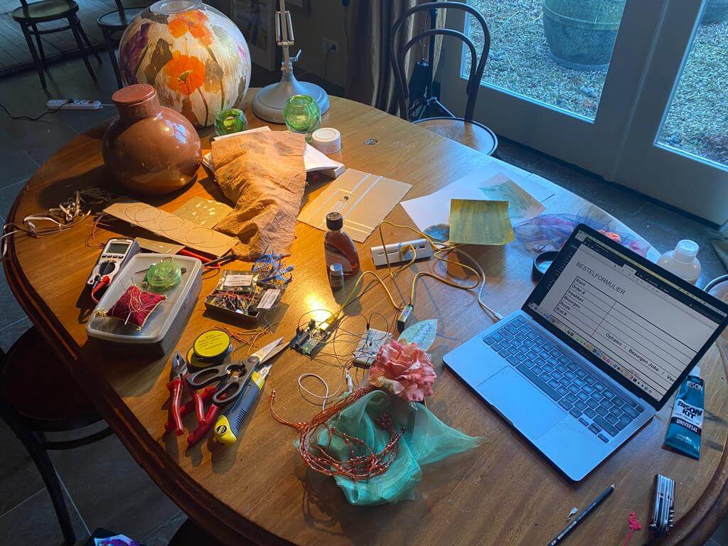
Due to some personal obligation, I was forced to work from home the whole of last week. I thought I had properly planned in advance, ordering an Arduino starter kit, and borrowing a MOSFET and some neopixels from Bea. However, while listening to Liza and Emma, and trying to get my first experiments from the ground, I soon realized I was short on a lot of handy materials and tools.
This was on my wish list:
- ATTiny
- Copper tape
- Alligator clips (I found a sad single pair here in the toolkit)
- Conductive thread
- Conductive fabric
- Crimp beads
- Magnets
- My soft sensors from the e-Textile week
The electronics and tool shops I visited, didn't sell my requirements. Fortunately bol.com came to the rescue, and last Friday I received some treasured thermochromic pigment and Nitinol shape memory alloy. I was off to the races!
Short introduction
A soft circuit for wearables consists of traces, sensors and actuators.
Traces are the physical paths of conductive material that electricity moves along in a circuit.
Sensors are components that provide information or data that enter the circuit. There are two types of sensors. Namely, digital sensors (switches) that make or break a complete circuit, like a button press. And analog sensors that are also called variable resistors. By allowing more of less electricity to flow through the circuit, analog sensors can drive the output.
An actuator is a component of a circuit that moves or controls another part based on input. An actuator in effect creates a state change. Those changes can be visual, sound, or motion.
Some examples of visual actucators:
- LEDs
- Neopixels
- Fiber optics
- Thermochromic ink
Some examples of sound actucators:
- Textile speakers
Some examples of motion actuators:
- Shape memory alloys
- Flip dots
- (Vibe) motors + haptics
This week we will mostly focus on actuators and coding for Arduino.
Building and coding sensors
To drive my actuators I needed sensors. However, at home I didn't have my soft sensors which we made during the e-Textile week. But on opening my Arduino starter kit I found many colorful components. So I decided to create the circuit and code for some sensors with those new toys from the kit.
Digital sensor
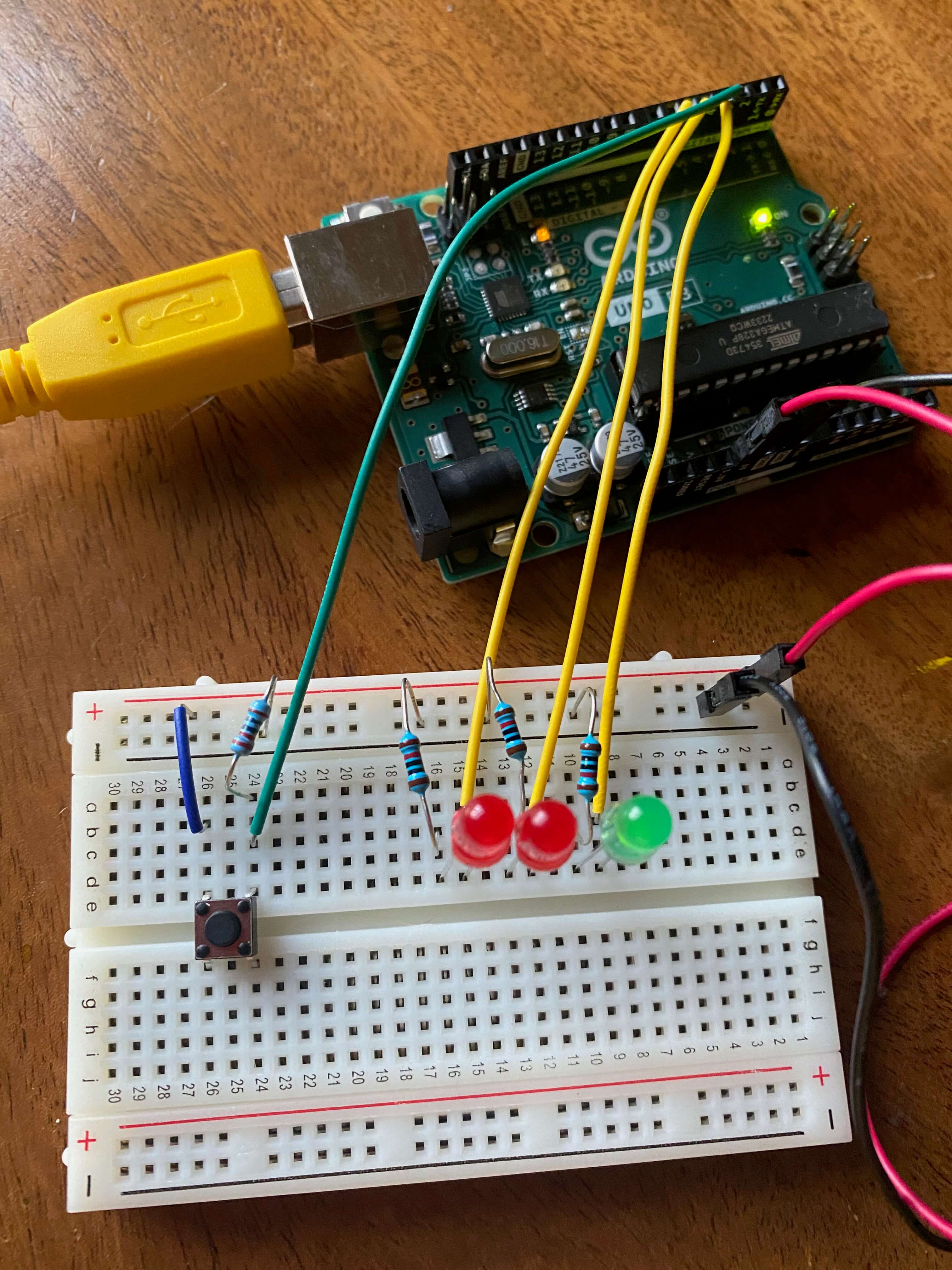
I started with a simple button switch (digital sensor). To make the circuit a bit more sexy I added three LEDs.
On the back of the starter kit box, I found a table with schematic symbols for the components in a circuit. So I decided to be a real pro in using these symbols to sketch out my circuit.
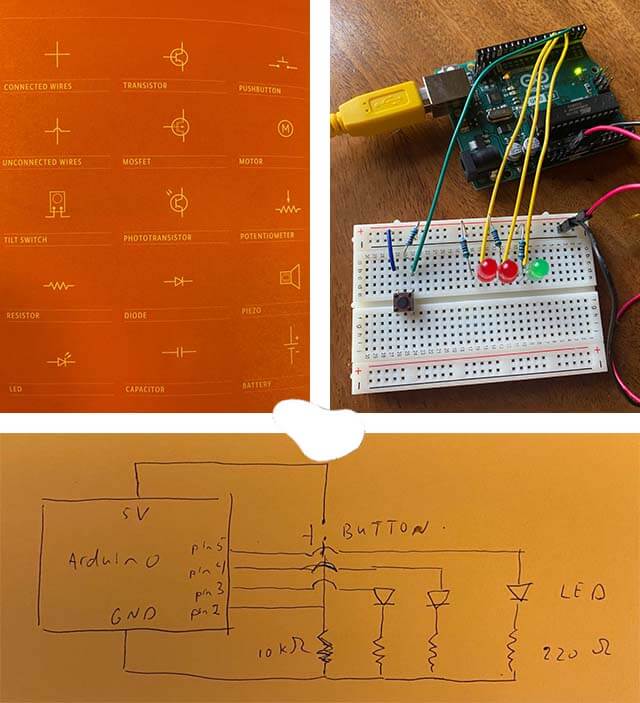
In order to practice a bit with if-statements, I set out to code the LEDs with some flashy behavior as soon as I would press the button.
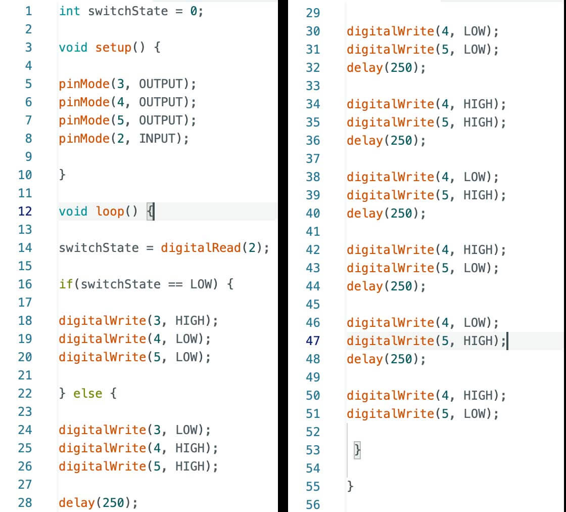
And tada, even at an older age you can be as happy as a child when things start flashing (and the dog got excited too)!
Starwars all over!
My digital sensor was ready! On to an analog sensor.
Analog sensor
For the analog sensor I set my eye on a capacitive sensor. I did read on the Arduino website that they are pretty unreliable because of their sensitivity to the environment. Computers, cables and wires, even the weather can interfere with the intended usage. But I still pressed on as I hoped that with that type of sensor I would be able to add a mysterious touch to some of my actuators.
A capacitive sensor is an electronic component that can detect solid or liquid targets without physical contact. To detect these targets, capacitive sensors emit an electrical field from the sensing end of the sensor. Any target that can disrupt this electrical field can be detected by a capacitive sensor. In other words, if for example you wave your hand above a capacitive sensor, you create a changing electric field, which can then be transformed as a variable input signal in your circuit.
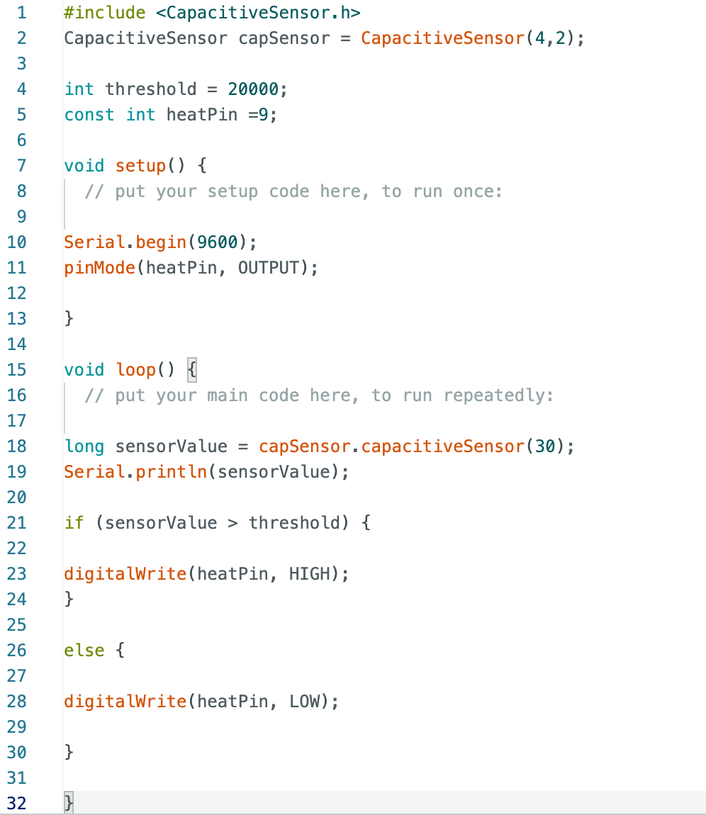
For Arduino to work with capacitance, the CapacitiveSensor library needs to be downloaded first. This library allows you to measure the capacitance of your body.
The circuit and code is not too exciting to start with. In the code, the value of 1000 for the threshold is the initial value. After programming the Arduino, you will want to find out what the sensor values are when you get close to or touch it. For this you need to open the serial monitor and review the values that get printed. Once it is clear what range of values the sensor is giving, the threshold value can be defined to a number greater than the sensor's value when it is not activated by touch or proximity.
When a 1 Ω resistor is used, the capacitive sensor must be touched to get a response. But by using a 10 Ω resistor in the circuit, the sensor gets more sensitive, and even getting closer might already lead to big changes which can be employed.
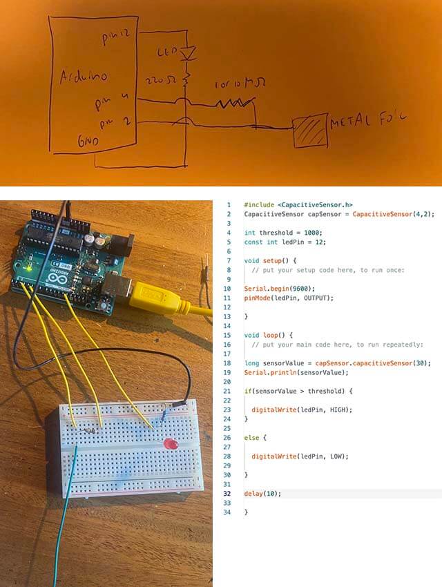
I included a LED to validate the usage of the capacitive sensor. Changing from a 1 Ω resistor to a 10 Ω resistor indeed required a different threshold.
Magic touch
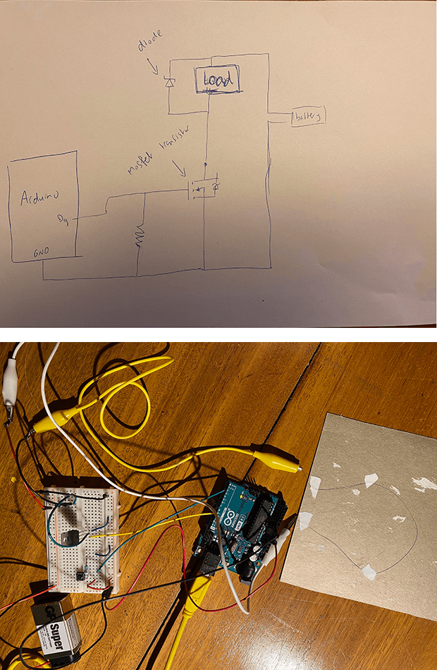
Preparing to use actuators: MOSFET circuit
Many of the possible actuators typically require more current than the Arduino can provide. Some require a higher voltage as well. To work with this kind of actuators they need a bit of extra circuitry in which a transistor is included.
Transistors are components that allow to control high current and high voltage power sources from the low current output of the Arduino. There are many different kinds, but they work on the same principle. Think of transistors as digital switches. When voltage is provided to one of the transistor's pins, called the gate, it closes the circuit between the other two pins, called the source and the drain. In this way, a higher current or voltage can be turned on and off with Arduino.
This week for a transistor we will use the N-channel MOSFET.
Liza and Emma explained how we could build such a circuit on a piece of cardboard. So I stuck conductive tape on my cardboard and soldered some connections to create my own circuit.
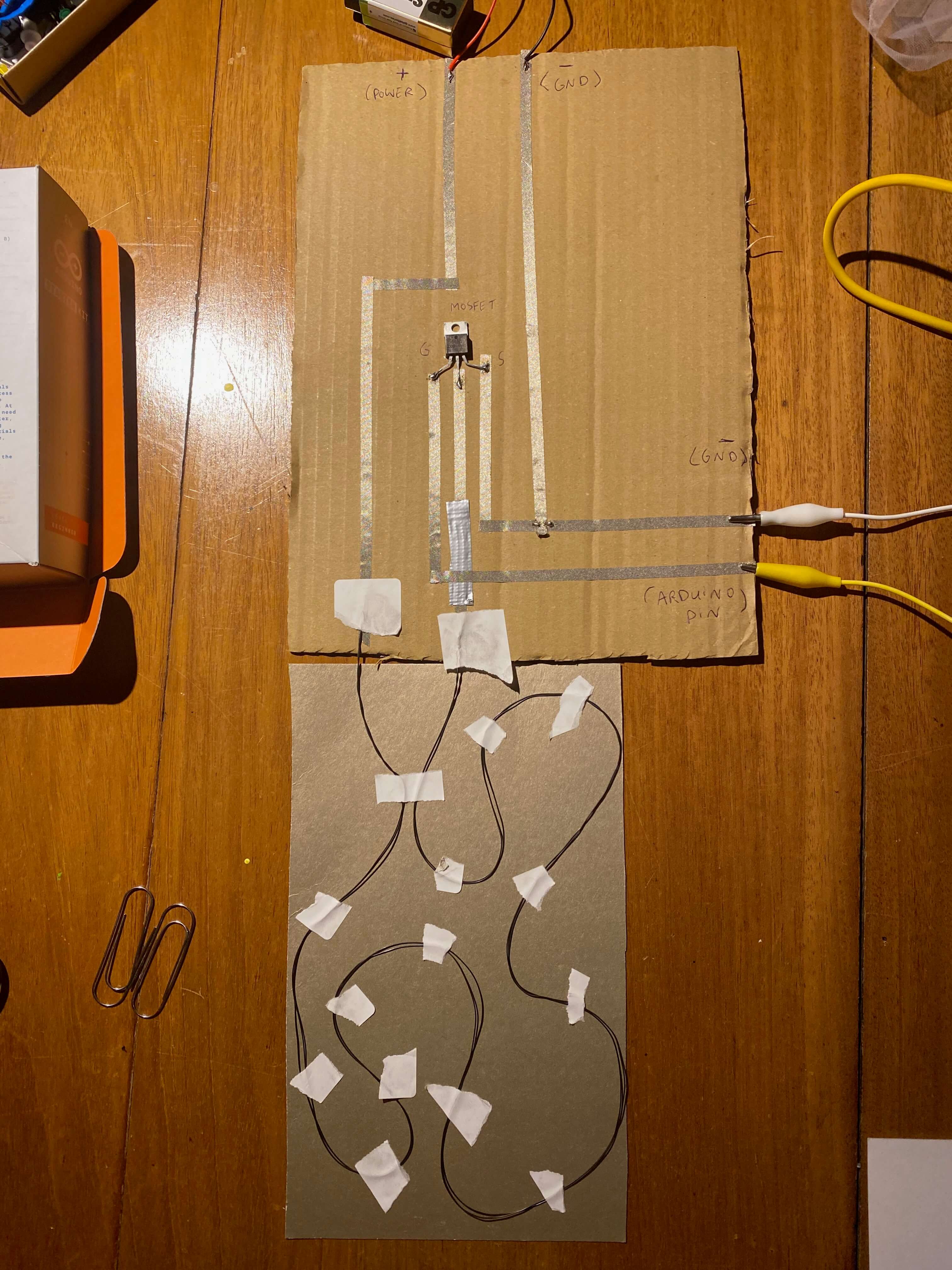
Unfortunately, without a sufficient number of alligator clips, it is rather difficult to connect actuators properly to the cardboard circuit (taping isn't the solution). So, after some unfruitful trial and error, I decided to abandon the cardboard circuit, and create the appropriate circuits on my breadboard.
Actuator 1: Motion with Servo motor
As a first actuator I selected a servo motor from my Arduino kit. Those are a special type of motor that don't spin around in a circle, but move to a specific position and stay there until you tell them to move again. Servos usually only rotate 180 degrees. The motor is controlled by sending electrical pulses from your Arduino board. These pulses tell the motor what position it should move to. The Arduino software comes with a library that allows you to easily control the motor.
Working with the Servo motor requires the following steps:
- Connect one side of a potentiometer to GND and the other to 5V
- Connect the middle pin of the potentiometer to pin A0
- Connect the red cable from the motor to 5V
- Connect the black cable from the Servo to GND
- Connect the white cable to pin 9
- Download and install the Servo library
- Include the Servo header file in the code
- Create a named instance of the Servo library in a variable in the code
- To define the angle the Servo motor has to rotate to, the Map function is handy
When a Servo motor starts to move, it draws more current than if it were already in motion. This will cause a dip in the voltage. By placing a 100 uf capacitor across power and GND, right next to the wires of the Servo motor, the voltage changes occuring can be smoothed out.
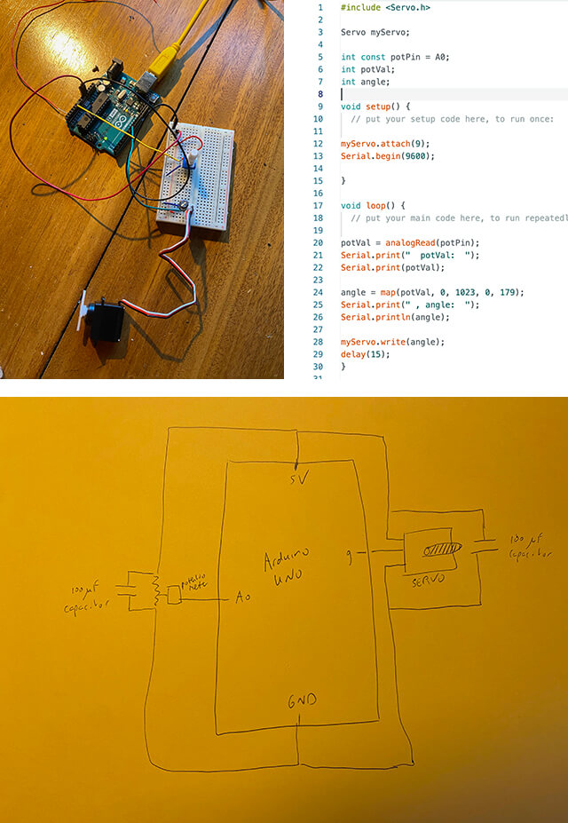
It is best to use an analog sensor, like a potentiometer to control Servo motors. This will provide (through the Map function) a full range of angles between 0-180 degrees. In fact, the Servo motor will exactly rotate along with the turning of the potentiometer
In the Biofabrication week I had grown some whey leather and created some shapes from casein. With a bit of fantasy and some color I could see elements of a flower in those items.
My servo motor became a flower swirling in the wind!
My swirling flower, a motion actuator
Actuator 2: Heating element with thermochromic ink
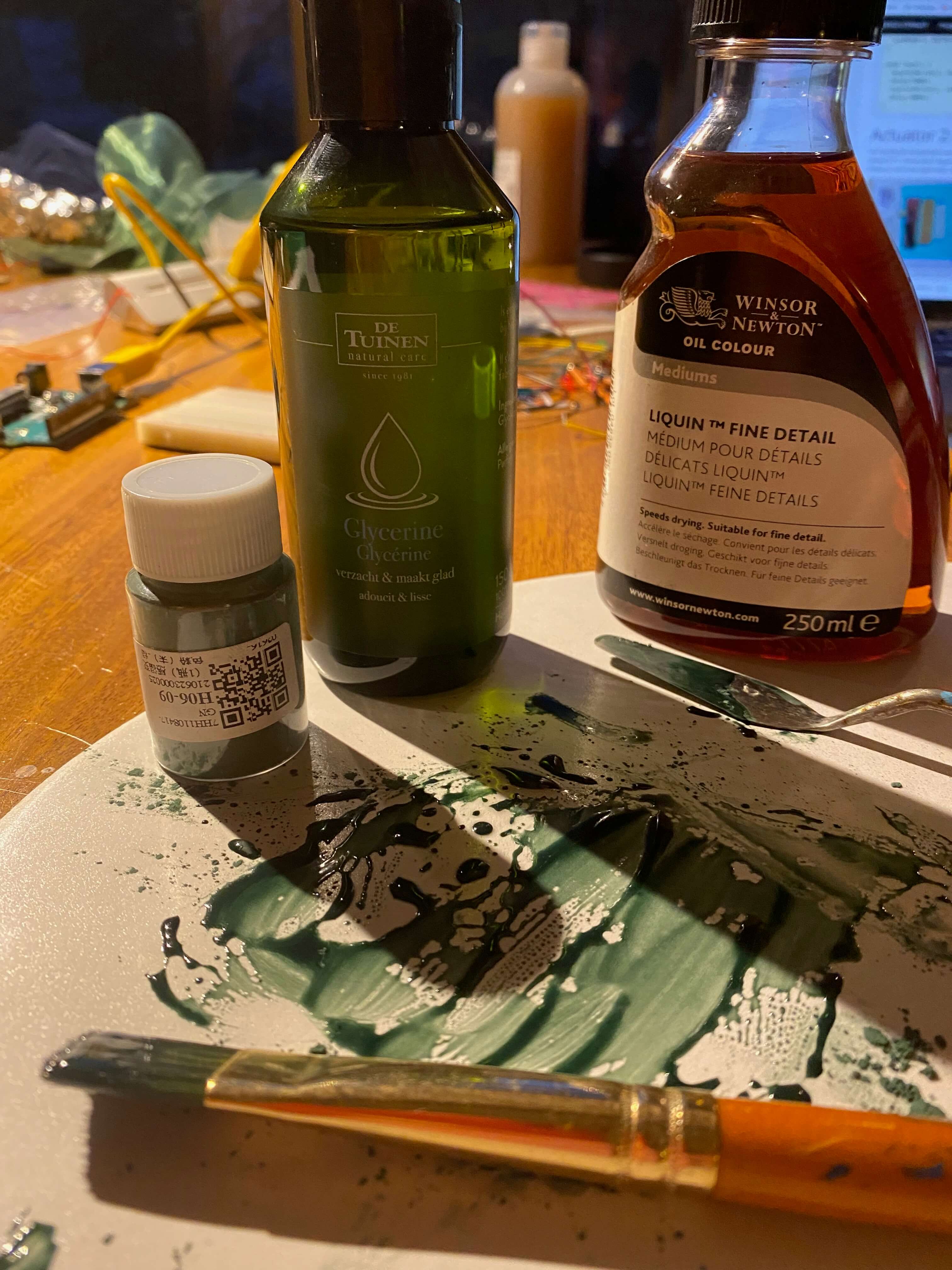
I had bought some green thermochromic ink that would fade color with a rise in temperature. Any medium, dye or ink can be used to dissolve the pigment powder. I decided to test it with glycerine and some Liquin (a painter's oil) I still had in my painting supply.
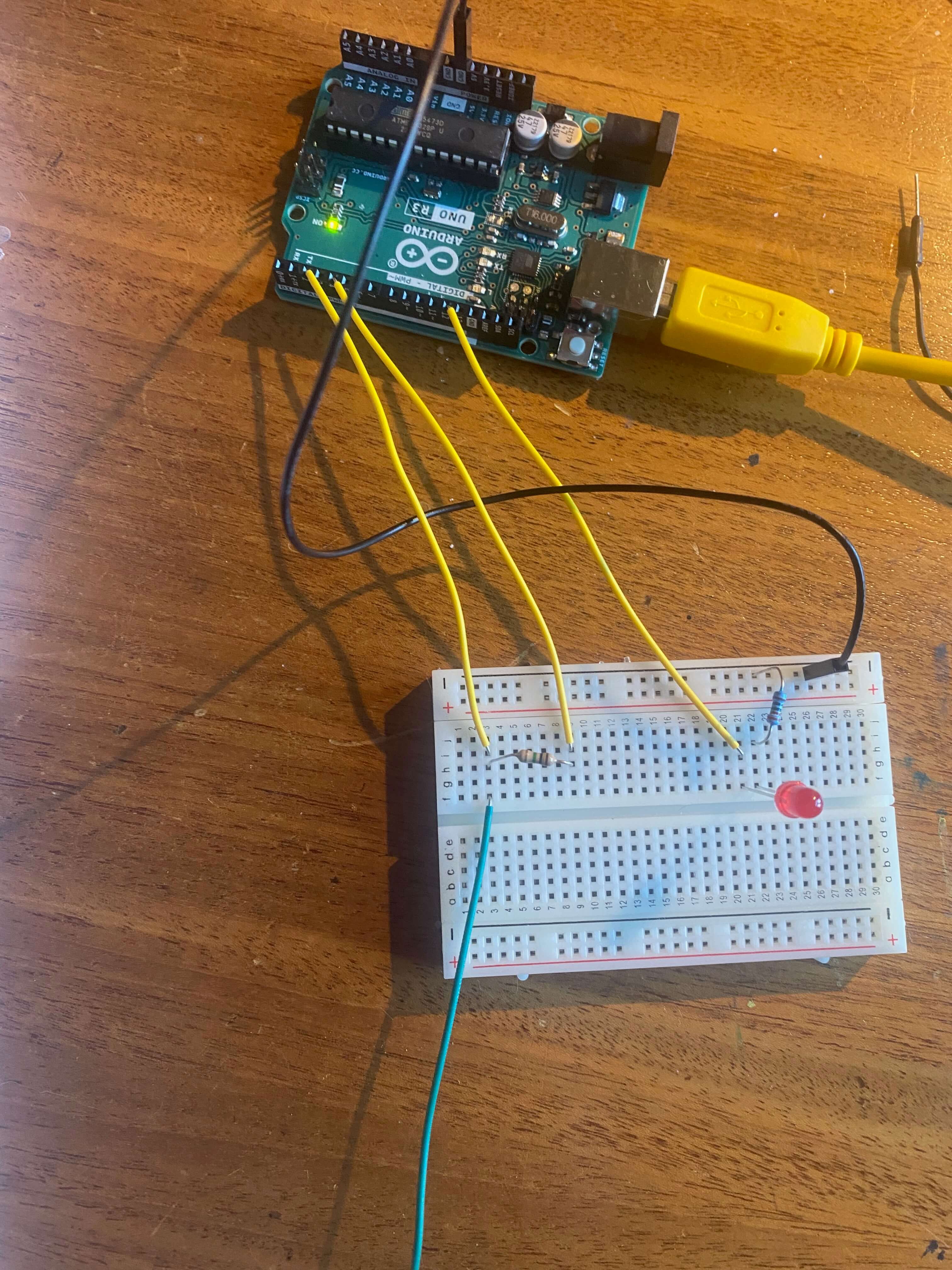
To play around with the thermochromic ink, you need to build a heating element first. The current is what generates the heat, so working with resistance is how you control the heat generation. A heating element can be build by connecting a resistant wire to the MOSFET circuit, which in turn is powered by an external battery.
As a wire I used the Nitinol shape memory wire. A heating element requires around 0,5-1A to provide some heat. I had a battery of 9V. So with help of Ohm's law I could calculate I needed a wire with a resistance between 9-18Ω.
Ohm's law:
V = I x R.
With help of my multimeter I measured the length of a piece of wire that had a resistance of around 10Ω, that would give me around 0,9A of current.
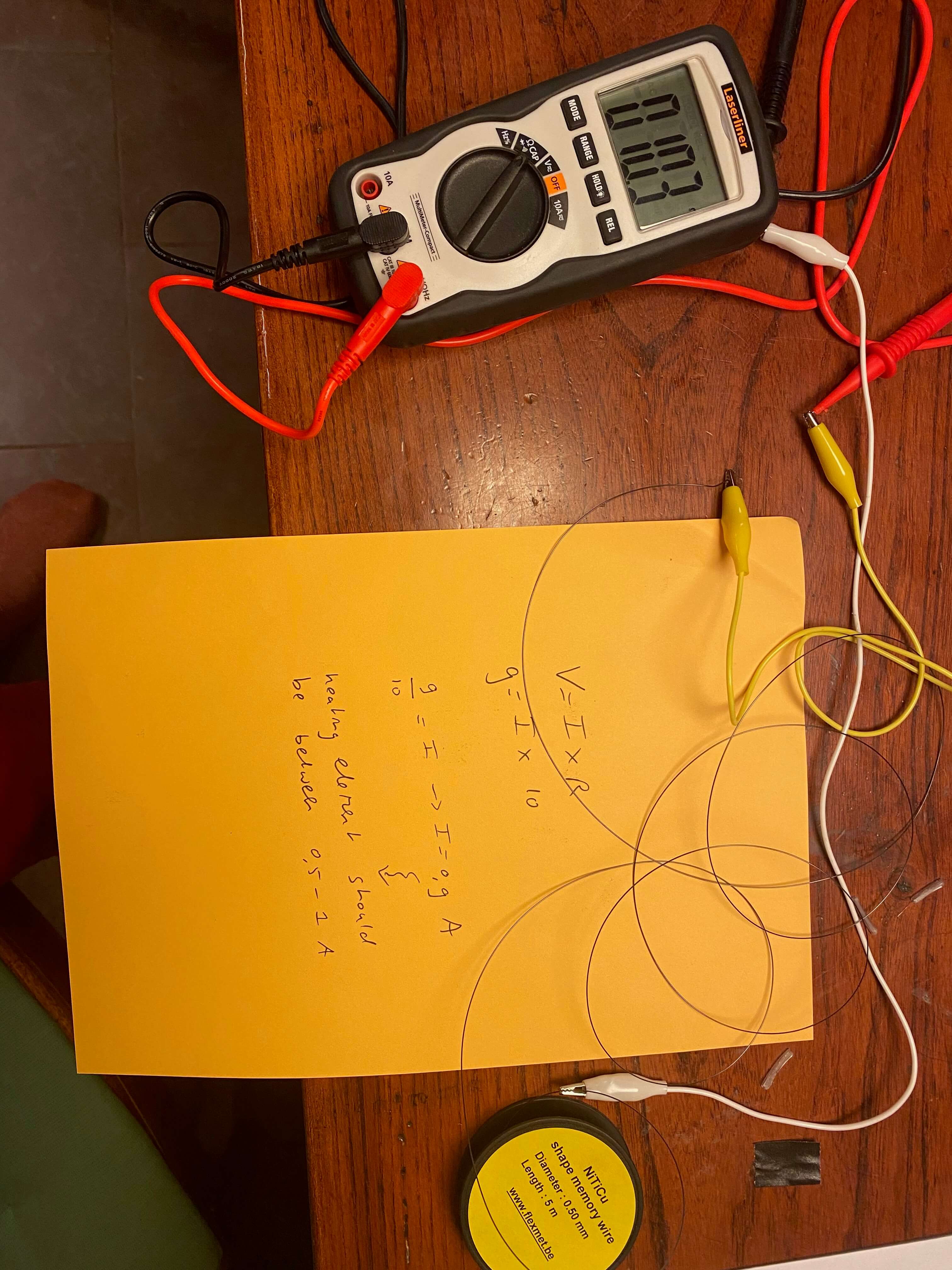
I taped the wire to cardboard, and once I had stuck it to the cardboard in a shape I measured another time the resistance. That had increased to around 15Ω, which was still in the ballpark to generate current in the range of 0,5-1A.
Since I could not connect my cardboard MOSFET circuit due to a lack of alligator clips (I had only two of them), I rebuild the MOSFET circuit on my breadboard and combined it with the digital button switch. I connected the breadboard to my battery and to the Nitinol wire on the cardboard. I was ready to heat things up!
The code for this circuit was rather simple.

Thermochromic powder and glycerine on paper
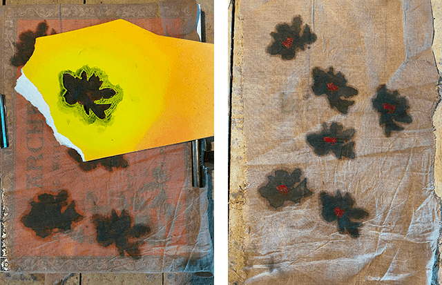
The first I did was mixing the thermochromic powder with some glycerine. With this mixture I painted some thick aquarel paper. By pushing the digital button, I closed the MOSFET circuit, and through my heating element flowed current which generated just enough heat. The effect on the thermochromic ink was beautiful. My first test was satisfactory!
First test with heating element
Thermochromic powder and Liquin on paper
I painted thick paper with yellow acryl paint. Once it was dry, I covered it with a mixture of the thermochromic powder and Liquin. I reshaped the heating wire for a different effect. I felt the result was almost like a flower slowly starting to blossom.
My appearing flower, thermochromic pigment on a heating element
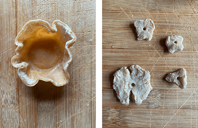
Thermochromic powder and Liquin on whey leather
I tested changing the carrier. So I used the powder/Liquin mixture to paint a whey leather pad I had grown some weeks before. Unfortunately the heating element did not cause any visual effect. It might be that the material is simply too thick, or the leather works as an insulator for the current. But whey leather is not a good carrier to use with thermochromic ink.
Whey leather is not a good carrier
Thermochromic powder and Liquin on fabric
Finally I made a mal of a rose, and used it to stipple with the powder/Liquin mixture this form on some cotton fabric.
Albeit less pronounced, the heating element worked it's magic on the fabric as well.
Actuator 3: Motion with Nitinol wire
For my last actuator I decided to experiment with using shape memory alloy to actuate paper. My goal was to create a leaf that would wave and curl when I came close with my hand. I used the Nitinol wire again, which is a wire that contracts when heated up.
I first cut out a leaf shape from paper and colored it with some crayons. On top of the paper I curled the Nitinol wire in a v-shape, and then stitched the wire to the paper with non-conductive thread. The v-shape is important to get the required pull on the paper. When heated, the wire shrinks and pulls the paper up, giving the impression of a waving and curling leaf. As the wire cools down, the rigidity of the paper counteracts the shape of the wire, allowing the leaf to get back to the original position.
I wound the ends of the Nitinol wire around two copper screws and turned both in a piece of wood.
Then I created the MOSFET circuit again on my breadboard and combined it with the digital button switch. I connected the breadboard to a 9V battery and to the copper screws which were attached to both ends of the Nitinol wire. Upon pushing the button, the leaf started curling. Since I had used wide stitches to fasten the Nitinol wire on the paper, the leaf did not curl perfectly straight, but in a way I liked the asymetric curl I got.
The next step I took was replacing the digital button switch with the analog capacitive sensor on the breadboard. The code was pretty straightforward.
Now by touching the jumper cable connected to port 2 on Arduino, I could control the motion of the leaf. To expand the impact of the capacitive sensor, I connected the end of the jumper cable to a piece of aluminium foil. The total surface of the foil was now sensitive to my hand movements.
As a last step I pimped my leaf with a flower and green fabric. Time to make a delicate dance with this artificial creature.
A delicate dance, Nitinol curling paper with capacitive sensor